GraceWood The Sturdy-Lite User manual

The Sturdy-Lite
Parts List
Wood Parts List............................................................................................... 2
Hardware Parts List ......................................................................................... 3
Care of Your Frame ......................................................................................... 4
Assembly Steps:
Step 1: Table Brace Assembly.......................................................................... 6
Step 2: Frame End Assembly........................................................................... 6
Step 3: Leg to Frame Assembly....................................................................... 7
Step 4: Leg Brace Assembly............................................................................ 7
Step 5: Complete Lower Frame Assembly......................................................... 8
Step 6: Rail Assembly ..................................................................................... 11
Step 7: End Cap Assembly .............................................................................. 11
Step 8: Rail to Pole Mount End Assembly ......................................................... 12
Step 9: Plastic Knob Assembly......................................................................... 13
Step 10: Complete Frame Assembly................................................................. 14
Step 11: Bottom Plate (Carriage Assembly) ...................................................... 15
Step 12: Top Plate Wheel (TPW) Assembly....................................................... 16
Step 13: Top Plate Lower Handle (TPLH) Assembly........................................... 17
Step 14: TP Upper Handle (UH) Assembly........................................................ 18
Step 15: TP Handle Assembly.......................................................................... 19
Step 16: Handle Linkage Assembly .................................................................. 20
Step 17: Spacer Assembly............................................................................... 21
Step 18: Pedal Pusher Assembly...................................................................... 22
Step 19: Cone Thread Holder Assembly ............................................................23
Step 20: Stylus Clamp Base Assembly.............................................................. 24
Step 21: Stylus Clamp Assembly (A) ................................................................ 24
Step 22: Stylus Assembly (B) .......................................................................... 24
Step 23: Stylus to Carriage Assembly............................................................... 24
Step 24: Placing the Top and Bottom Plates onto the Frame.............................. 25
Fabric Installation ....................................................................................... 25
Step 1: Making Cloth Leaders.......................................................................... 25
Step 2: Quilt Bottom To Back Rail .................................................................... 26
Step 3: Quilt Top To Middle Rail....................................................................... 27
Step 4: Install Quilt Bottom To The Take-Up Rail............................................... 28
Step 5: Batting Over The Backing.................................................................... 28
Step 6: Install Quilt Top To The Take-Up Rail.................................................... 29
Rolling your Fabric........................................................................................... 30
The Four-Inch Principle.................................................................................... 30
Optional Accessories ........................................................................................30
Copyright December 2005
Jim M. Bagley, GraceWood, Inc
(Reproduction Prohibited)

-2-
(1) Left Pole Mount End (1) Right Pole Mount End
(2) Frame End (4) Table Brace
(1) Left Top Handle
(1) Back Lever
Linkage (1) Back Lever (1) Front Lever (1) Middle Lever
(1) Front Lever
Linkage
(3) Pedal
Clamp Spacer
(1) Pedal
Clamp Wheel
(4) Table Track
Support
(4) Leg
(2) Middle Leg
(1) Pedal Clamp
(1) Lamp Holding
Cross Brace
(1) Back Handle
Cross Brace (1) Right Bottom
Handle
(1) Left Bottom
Handle
(4) Leg Brace
(1) Right Top Handle
(1) Middle Leg Brace
Sturdy-Lite
Wood Parts List
(1) Stylus Base
(1) Stylus Clamp
(1) Stylus Mount
(1) Wooden Stylus
(3) Cone
Thread Holder
(1) Back Handle
Narrow Cross Brace
(1) Top Plate (1) Bottom Plate

-3-
(26) 1/4" X 30mm
Connector Bolt
(18) 1/4" X 35mm
Connector Bolt
(6) 1/4" X 45mm
Connector Bolt
(5) 1/4" X 50mm
Connector Bolt
(1) 1/4" X 60mm
Connector Bolt
(12) #10 X 3/8"
Socket Head Screw
(3) 1/4" X 1-1/2"
Truss Bolt
(6) 1/4" X 1-1/2"
Phillips Pan Head Screw
(6) 1/4" X 2"
Phillips Pan Head Screw
(4) 1/4" X 3" Carriage Bolt
(9) 1/4"
Plastic Knob
(23) 3/16"
Washer
(8) 1/4"
Nylock Nut (17) 1/4"
Jam Nut (24) 1/4"
Square Nut
(6) #10
Square Nut
(24) 1/4"
Cap Nut
(7) 1-1/4"
Fender Washer
(8) 1-1/4"
Wheel
(3) Rail Coupler
(3) 34" Aluminum Rail
(3) 64" Aluminum Rail
(2) 99" Plastic Track
(6) Rail
Shoulder Piece
(3) Round
End Cap
(3) Square
End Cap
(3) Ratchet Wheel
(3) Cog Stop
(8) 1/4"
Washer
(2) 20" Plastic Track
(1) 3mm
Allen Wrench
(1) Fabri-Fast Tool
(2) 4mm
Allen Wrench
Sturdy-Lite
Hardware Parts List
(6) #8 X 7/8"
Screw
(1) 1/4" X 2"
Eye Bolt
(2) #10 X 3"
Eye Bolt
(4) #10 Hex
Nut

-4-
CARE OF YOUR STURDY-LITE
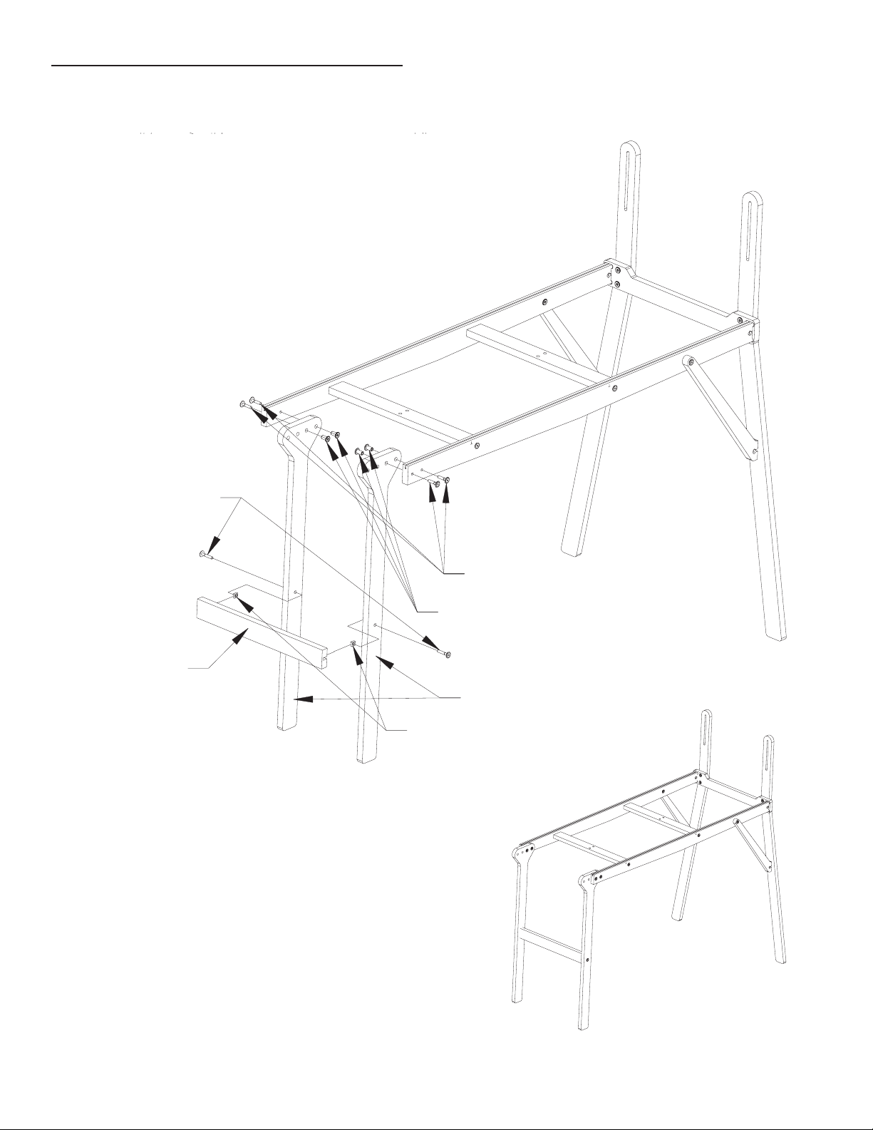
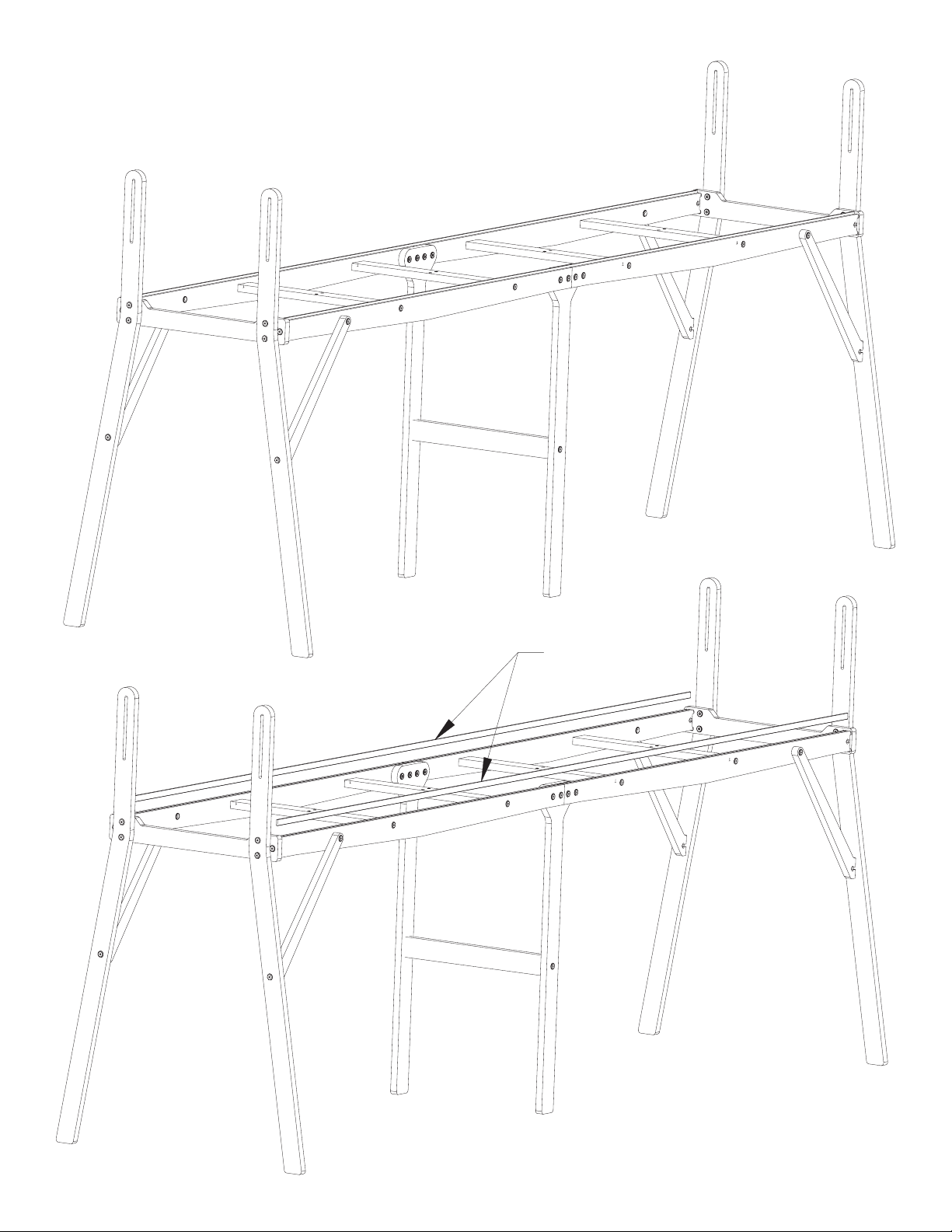
Your Sturdy-Lite frame is a machine quilting system that can be used nished or unnished.
Most use it unnished with no problem, and doing so does not adversely affect warranty coverage.
However, for extra protection, or to give it a nished look, you may seal, stain and/or nish the frame
using a number of different applications. This is best done BEFORE YOU ASSEMBLE your frame.
To seal the wood, we recommend an application of tung oil or Danish Oil nish that will help
preserve the wood and will help to prevent warping. We recommend the McCloskey’s Tung Seal,
DeftTM or WatcoTM brands. Some prefer to use a urethane coat to add a more glossy nish.
Test stain on an inconspicuous place. Many different nishes and/or stains may be suitable for
sealing and beautifying your frame. You may want to consult your local paint retailer for nishes that
are easy to apply and dry hard–not oily.
Use and Storage Tip
--Store frame in a dry place. Avoid the possibility of moisture coming into contact with your wood.
Five-Year Limited Warranty
GraceWood, Inc. will replace or repair, at our choosing, any part of the Sturdy-Lite Machine
Quilting System which may be shown to be defective. This warranty does not cover parts damaged
through misuse, improper storage, improper assembly, loss, natural events and willful or accidental
destruction. Defective parts may be returned only with a valid RMA# which may be obtained by
calling GraceWood, Inc. at
1-800-264-0644 or 1-801-485-6688.
NOTE: Warranty card must be lled out, stamped and mailed to the address on the card within 30
days of purchase.
Contact Information
For Technical Support or any other correspondence concerning your Sturdy-Lite, call 1-800-264-0644
~
OR ~ E-mail: paul@graceframe.com ~ OR ~ Fax: (801) 908-8888 ~
OR ~ Write to:
The Grace Company
P.O. Box 27823
Salt Lake City, UT 84127
For details on accessories and other information, see us online at www.graceframe.com
For shipping of materials to The Grace Company address package (postage prepaid) to: The Grace
Company, 2225 South 3200 West, SLC, UT 84119. Materials may be returned only with a valid
RMA# or Returned Merchandise Authorization Number which may be obtained by calling GraceWood,
Inc. at
1-800-264-0644.
If you call after business hours (M-F 8:00 a.m. – 5 p.m., MST) be assured that your call will be
returned the next business day if you leave a message. Please report any errors in these instructions
or make comments to the following: jaren@graceframe.com
Grace Quilting Frames and Hoops: Innovation and Evolution
Grace Quilting Systems have been developed over the past two decades with several original
design innovations. Additionally, because of feedback from many of the thousands of quilters who
have purchased and use our machine quilting systems, we have been able to make a frame that
will truly enhance the entire process of machine quilting from beginning to end. If you have any
suggestions that will help us to improve our product or service, let us know, using one of the above
contact methods.

-5-
WELCOME!
As you begin assembly of your new Sturdy-Lite home machine quilting system, keep in the
mind the following:
1: Plan to spend a minimum of 2-4 hours in assembly. This process will be simple and step-by-step.
2: Read through each step completely before beginning that step.
3: Using the parts list as a reference, take the parts out of the box and make sure that you have them all. (If
there is something missing or broken, contact the Grace Company at 1-800-264-0644. Our ofces are open
from 8:00 am-5:00 pm MST Mon.-Fri. If calling after hours, you may leave your message and we will promptly
ship any item needed).
4: Identify Hardware Packets: All hardware is separated by type and each packet is labeled for ease in
identication you will nd packets located in a rectangular box.
5: This is a new product! We welcome your feedback on this product or these instructions. If you encounter
a problem during assembly or use of the Sturdy-Lite, and you can’t seem to overcome it, call us before
frustration sets in!
Tools Needed:
7/16” Socket Wrench
Adjustable wrench
Phillips Screw Driver (Cordless Preferred)
Allen wrench (provided)
Fabri-Fast Tool (to be used when installing your fabric)

-6-
1/4" X 35mm
Connector Bolt
Table Brace
Rail Tarck Support
1/4" X 35mm
Connector Bolt
Frame End
1/4" X 35mm
Connector Bolt
Table Brace
Rail Tarck Support
1/4" X 35mm
Connector Bolt
Frame End
1/4" X 35mm
Connector Bolt
Table Brace
Rail Tarck Support
1/4" X 35mm
Connector Bolt
Frame End
1/4" X 35mm
Connector Bolt
Table Track Support
Table Brace
1/4" Square Nut
Fig. 1-1
Fig. 1-2
Step 1: Table Brace Assembly
Parts Needed:
4- Table Brace
4- Table Track Supports
8- ¼” x 35mm Connector Bolt
8- ¼ #20 Square Nut
Step 2: Frame End Assembly
Parts Needed:
2- Frame Ends
2- Table Brace Assembly
4- ¼” x 35mm Connector Bolt
4- ¼” Square Nut
**Square Nuts may need to
be pushed in with a screw
driver or tapped in with a
hammer.**
1-1: Attach two Table Braces to
two of the Table Track Supports.
Place the Table braces on your
working surface with the “T” slots
facing up. Also place the Table
Track Supports on your working surface with the two
holes closest to the end to your left, and the edge with
the slot running it’s entire length facing down.
1-2: Insert a square nut into all of the “T” slots in
each of the Table Braces. Then insert a 35mm connector bolt through
each of the appropriate holes in the Table Track Supports. Now thread the bolt into the square nuts
already in the “T” slots of the Table Braces. Tighten the bolts with a 4mm Allen wrench (Supplied in
hardware kit).
1-3: Repeat steps 1-1 and 1-2 to build another
Table Brace Assembly.
2-1: Flip the Table Brace Assembly
so the slotted edges face up.
2-2: Place a square nut into the
“T” slots at the ends of each Table Track
Support.
2-3: Insert 35mm bolts through the Frame End, and thread into
the square nuts (previously installed), as show Fig. 2-2.
2-4: Repeat steps 2-1 to 2-3 to build another Frame End Assembly.
Fig. 2-2
Fig. 2-1

-7-
30mm Conector Bolt
1/4" Square Nut
35mm Connector Bolt
1/4" Cap Nut
Leg Brace
30mm Conector Bolt
1/4" Square Nut
35mm Connector Bolt
1/4" Cap Nut
Leg Brace
30mm Connector Bolt
1/4" Cap Nut
Leg
Fig. 4-1
Fig. 3-2
Fig. 3-1
Step 3: Leg to Frame Assembly
Parts Needed:
2- Frame End Assembly
4- Legs
8- ¼” x 30mm Connector Bolt
8- ¼” Cap Nut
Step 4: Leg Brace Assembly
Parts Needed:
4- Braces
4- ¼” x 30mm Connector Bolt
4- ¼” Cap Nut
4- ¼” x 35mm Connector Bolt
4- ¼” Square Nut
4-1: Put a square nut into the “T”
slots in each of the Leg Braces.
4-2: Put a 35mm connector bolt
through the hole on each Leg.
4-3: Now screw the bolt into the nut
that you installed in the Leg Brace.
4-4: Insert a 30mm connector bolt
through the brace and into the Table
Track Support.
4-5: Insert a Cap Nut through the hole
in the Table Track Support, then thread
onto the end of the bolt.
4-6: Follow the above steps for the
remaining three Leg braces.
3-1: Attach the Legs to the Frame End
Assembly using (2) 30mm Connector
Bolts, and (2) 1/4” Cap Nuts per leg, make
sure the Legs angle outward as shown.
3-2: Create another Leg to Frame
Assembly by repeating this step.

-8-
1/4" X 30mm
Connector Bolt
1/4" Cap Nut
Middle Leg
35mm Connector Bolt
1/4" Square Nut
Middle Leg Brace
1/4" X 30mm
Connector Bolt
1/4" Cap Nut
Middle Leg
35mm Connector Bolt
1/4" Square Nut
Middle Leg Brace
Fig. 5-1
Fig. 5-2
Step 5: Complete Lower Frame Assembly
Parts Needed:
2- Middle Legs
1- Middle Leg Brace
2- 35mm Connector Bolt
8- 30mm Connector Bolt
2- 1/4” Square Nut
8- 1/4” Cap Nut
2- 99” Plastic Track
5-4: Insert square nuts into the “T” slots in the Middle
Leg Brace.
5-5: Attach the Middle Leg Brace to the Middle Legs by
inserting a 35mm bolt through the holes in the middle
legs, then screw tightly into the square nuts previously
inserted in the middle leg brace
5-1: Put (2) two 30mm bolts through the (2) two
holes on one of the Table Track Supports.
5-2: Attach a Middle Leg to the Leg Frame
Assembly with (2) two 1/4” Cap Nuts per
leg. Do not completely tighten these
bolts yet.
5-3: Attach the other
middle leg by following
the previous steps.

-9-
1/4" X 30mm
Connector Bolt
1/4" Cap Nut
1/4" X 30mm
Connector Bolt
1/4" Cap Nut
Fig. 5-3
Fig. 5-4
5-6: Attach the other Leg Table Assembly to the Middle Leg and Track Assembly by securing the
Table Track Supports to the middle legs using (2) 30mm bolts, and (2) 1/4” Cap Nuts per middle leg.
5-7: Now completely tighten the screws holding the middle legs onto the table assembly.

-10-
Plastic Track
Fig. 5-5
Fig. 5-6
5-8: Once the legs are on, place the two pieces of 99” Plastic Track into the
grooves in the Rail Track Supports.
5-9: Run hand across track to ensure track is completely seated into the slot.

-11-
Coupler
#10 Socket Head Screw
Fig. 6-1
Round End Cap
#10 Socket Head Screw
#10 Square Nut
Fig. 7-1
Step 6: Rail Assembly
Parts Needed:
3- 64” Rail
3- 34” Rail
3- Rail Coupler
6- #10 Socket Head Screws (SH)
6- #10 Square Nut
6-1: Insert one end of the coupler into the end of the 64” rail. Screw a #10 socket head screw
through the second hole from the end of the rail and into the threaded hole of the coupler. Tighten
the screw all the way using small Allen wrench.
6-2: Slide one end of the 34” rail onto the coupler and screw a #10 socket head screw in the
coupler as before.
6-3: Repeat the above steps to assemble two more identicle rails.
Step 7: End Cap Assembly
Parts Needed:
3- Round End Caps
3- Square End Caps
6- #10 Socket Head Screws (SH)
6- #10 Square Nut
7-1: Install one round end cap onto the end of each 34”
Rail.
7-2: To do this place a square nut into the square slot in the
end cap then insert the end cap into the end of the 34” rail.
* Remove clear plastic tubing from rails,
and save for later use.

-12-
Queen Size Rail
64" Rail 34" Rail
#10 Socket Head Screw
#10 Square Nut
Square End Cap
Fig. 7-2
Fig. 7-3
Ratchet Wheel
7-3: Next, secure the end cap to
the rail by inserting a #10 socket
head screw through the hole
in the rail and into the square
nut in the end cap, (tighten
completely).
7-4: Follow the above instructions to put
the rest of the round end caps on the 64”
Rails.
7-5: Follow the above instructions again,
this time attatching the square end caps to
the other end of the rails.
Step 8: Rail to Pole Mount End Assembly
Parts Needed:
3- Rail Assembly
1- Right Pole Mount End
1- Left Pole Mount End
3- Ratchet Wheel
3- Ratchet Stop
6- End Cap Shoulder
6- #8 x 7/8” Screw
3- ¼” x 1 ½” Truss Bolt
Fig. 8-1
8-1: Slide your Ratchet Wheels onto the
square end caps that you attached to the
aluminum rails in step 7.
8-2: The direction that the Ratchet Wheels point will allow
you to apply tension to your quilt fabric, if the teeth are installed
pointing backwards your frame won’t work correctly.
8-3: Make sure that the teeth on (2) of the
Ratchets point clockwise, and on the other
ratchet the teeth need to point counter-
clockwise. (Fig 8-2 displays
the correct wheel direction,
and placement on the frame.)
8-4: Next attach the rails to the Pole Mount Ends.
8-5: Make sure that the ends
of the rails with the Ratchet
Wheels get attatched to the Left
Pole Mount End.
Fig. 8-2

-13-
Shoulder End Cap
#8 X 7/8" Screw
1/4" X 2" Phillips
Pan Head Screw
1/4" Plastic Knob
1/4" Jam Nut
1/4" X 2" Phillips
Pan Head Screw
1/4" Plastic Knob
1/4" Jam Nut
Fig. 8-3
Step 9: Plastic Knob Assembly
Parts Needed:
4- 2” Phillips Pan Head Screw (PPH)
4- ¼” Plastic Knob
4- ¼” Jam Nut
9-1: Thread one bolt through each knob, with the
head of the bolt seating down inside the top of the
knob. (Fig. 9-1)
9-2: Screw a jam nut onto the end of each bolt,
tighten securly using a 7/16” wrench.
Fig. 9-1
Fig. 9-2
8-6: Securely fasten your rails to the Pole Mount Ends by attaching a Shoulder End
Cap to each square, and also each round end cap using a #8 X 7/8 screw. (Fig. 8-3)

-14-
Left Pole
Mount End
Right Pole
Mount End
Plastic Knob Assembly
1-1/4" Fender Washer
Plastic Knob Assembly
1-1/4" Fender Washer
Plastic Knob Assembly
1-1/4" Fender Washer
Rail to Pole Mount End Assembly
Complete Lower Frame Assembly
1/4" X 1-1/2"
Truss Bolt
Ratchet Stop
Fig. 10-2
Fig. 10-3
10-1: Attatch Rail
to Pole Mount End
Assembly to the Complete
Lower Frame Assembly
by rst placing the Rail to
Pole Mount End Assembly
between the upper portion of
the outer legs of the Complete
Lower Frame Assembly.
10-2a: Next insert a Plastic
Knob Assembly through the
slot in each of the outer Legs,
and into the hole in the
pole mount end that has a
threaded metal insert in it.
Tighten the knobs. (You may
need to loosen the bolts attatched in
step 3-1 to get the holes to line up.)
10-2b: Tighten the bolts from step 3-1
in the outer Legs if you loosened them
to gain proper hole alignment in step
10-2a.
Step 10: Complete Frame Assembly
Parts Needed:
1- Rail to Pole Mount End Assembly
1- Complete Lower Frame Assembly
4- Plastic Knob Assembly
4- 1-¼” Fender Washers
Fig. 10-1
10-3: Attatch ratchet stops to the Left
Pole Mount End using 1-1/2” Truss Bolts.
(Fig. 10-2, Fig. 10-3)
10-4: HAND TIGHTEN ONLY! Over
Tighting these bolts may damage the Pole
Mount End.
NOTE: Notice that 2 of the rails on the Rail to Pole
Mount End assembly are closer together than the other
one. When the Rail to Pole mount end assembly is
attatched to the Complete Lower Frame assembly the
side of the frame that has the 2 rails closest together
becomes the front of the frame. Be careful to locate
the front of the quilting frame away from walls or other
obstructions, to allow easy acces to the front of the
frame while quilting.

-15-
1/4" X 2"
Phillips Pan Head Screw
1/4" X 1-1/2"
Phillips Pan Head Screw
1/4" Jam Nut
3/16" Flat Washer
1/4" Jam Nut
Steel Wheel
1/4" Jam Nut
3/16" Flat Washer
Fig. 11-1
Plastic Track
Step 11: Bottom Plate (Carriage) Assembly
Parts Needed:
1- Bottom Plate (Carriage), or (BP)
4- Wheels
8- ¼” Jam Nut
4- 3/16” Flat Washer (FW)
2- ¼” x 2” Phillips Pan Head Screw (PPH)
2- ¼” x 1½” Phillips Pan Head Screw (PPH)
2- 20” Plastic Track
11-1: Wheels are attatched to one end of
the Bottom Carriage with 1-1/2” Phillips Pan
Head Screws.
11-2: After inserting the 1-1/2” screws
through the holes in one end of the
carriage, apply a 3/16 washer, and then
a Wheel. Secure this assembly to the
carriage with a 1/4” jam nut. (See right side
of illustration, Below)
11-3: The wheels on the other end of
the Bottom Carriage are attatched with 2”
Phillips Pan Head Screws.
11-4: After inserting the 2” PPH screws through the
holes in the carriage apply a 3/16” Flat Washer. Now
secure the 2” PPH Screws to the carriage with a 1/4”
jam nut.
11-5: Apply a 1/4” Jam Nut, followed by a Wheel, now lock the position of the wheel with another
Jam Nut. (Fig. 11-1)
11-6: The wheels on this end of the carriage need to be 18-1/2” from the wheels on the other end
of the carriage. This measurment is based on center of wheel to center of wheel distance. If the
carriage doesn’t roll smoothly when you place it on the frame, further adjustment is required, and
will need to be done to this side of the carriage.
11-7: Insert the 20” Track into the groove
on each side of the Bottom Carriage.
(Fig. 11-2)
Fig. 11-2

-16-
1/4" Jam Nut
3/16" Washer
1/4" Washer Wheel
1/4" X 1-1/2"
Pan Head Screw
1/4" Jam Nut
3/16" Washer
1/4" Washer Wheel
1/4" X 1-1/2"
Pan Head Screw
12-1: To attatch wheels to
the Top Plate, rst apply a
Wheel to each of the 1-1/2”
PPH Screws, follow this with
a 3/16” Washer.
12-2: Now insert the screws
into each of the wheel holes.
(Use Fig. 12-1 to help determine which holes are the wheel holes.)
12-3: Next apply a 3/16” Flat Washer, and nally fasten the assembly to the carriage with a 1/4”
Jam Nut.
Fig. 12-2
Step 12: Top Plate Wheel (TPW) Assembly
Parts Needed:
1- Top Plate (Carriage), or (TP)
4- Wheels
4- 1 ½” Phillips Pan Head Screw (PPH)
4- ¼” Washer
8- 3/16” Washer
4- ¼” Jam Nut
Fig. 12-1

-17-
Right - Lower Handle
Left - Lower Handle
30mm Connector Bolt
1/4" Cap Nut
Right - Lower Handle
Left - Lower Handle
30mm Connector Bolt
1/4" Cap Nut
13-1: To attatch the
Bottom Handles to the TPW
Assembly, insert 30mm
Connector Bolts through
holes in carriage as shown in
Fig. 13-1.
13-2: Place one of the
bottom handles onto
one set of screws,
previously inserted
into the carriage
13-3: The pockets near the top of the handles
must face the carriage. This is shown in the
upper-left portion of Fig. 13-2.
13-4: Fasten the Bottom Handles to the TPW
Assembly with 1/4” Cap Nuts.
13-5: Repeat steps 13-1, to 13-4 to attatch the
other handle.
Fig. 13-1
Fig. 13-2
Step 13: Top Plate Lower Handle (TPLH) Assembly
Parts Needed:
1- TPW Assembly (Step 12)
1- Right Bottom Handle
1- Left Bottom Handle
4- ¼” x 30mm Connector Bolt
4- ¼” Cap Nut

-18-
30mm Connector Bolt
45mm Connector Bolt
Lamp Holding Cross Brace (LHCB)
Back Handle Cross Brace (BHCB)
Right - Top Handle
Left - Top Handle
1/4" Square Nut
30mm Connector Bolt
45mm Connector Bolt
Lamp Holding Cross Brace (LHCB)
Back Handle Cross Brace (BHCB)
Right - Top Handle
Left - Top Handle
1/4" Square Nut
Fig. 14-2
Fig. 14-1
step 14-2
Step 14-3
Step 14-5
Step 14-7
Step 14-5
14-1: Place the BHCB between your Bottom Handles with the
“T” slots facing down.
NOTE: If you are going to use a speed control device, or stitch
regulator use the Back Handle Narrow Cross Brace instead of the
Back Handle Cross Brace. Fig. 18-1 shows the installed Back Handle
Narrow Cross Brace installed.
14-2: Take your Right and Left Top Handles and put two of the 45mm connector bolts through the
back two holes on each handle, as show below.
14-3: Place a nut inside each of the “T” slots in the BHCB.
14-4: Thread the bolts through the holes on the Right and Left Bottom Handles and into the nut in
the BHCB.
14-5: Place a nut inside each of the “T” slots in the LHCB.
14-6: Put the LHCB between the Right and Left Top Handles. **NOTE you will have to pry the
handles apart to get the Spacer in.**
14-7: Once you have the spacer in put a 30mm connector bolt through the hole and tighten it
securely into the nut.
Step 14: TP Upper Handle (UH) Assembly
Parts Needed:
1- TPLH Assembly (Step 13)
1- Right Top Handle
1- Left Top Handle
1- Lamp Holding Cross Brace (LHCB)
1- Back Handle Cross Brace (BHCB)
1- Back Handle Narrow Cross Brace (BHNCB)
2- ¼” x 30mm Connector Bolts
4- ¼” x 45mm Connector Bolts
6- ¼” Square Nut

-19-
Back Lever
Middle Lever
Front Lever
1/4" Washer
3/16" Washer
1/4" Nyloc Nut
Back Lever
Middle Lever
Front Lever
1/4" Washer
3/16" Washer
1/4" Nyloc Nut
Step 15-1
Step 15-2
Step 15-3
Nylock Nut Rules: Nylock nuts are
used to allow the parts being bolted
together to move. Nylock nuts will not
loosen after threaded onto a bolt. So,
whenever a nylock nut is used keep
in mind that one of the parts will
need to pivot freely. This being
the case, remember to not over
tighten Nylock Nuts.
Fig. 15-1
Fig. 15-2
15-1: • a - Attatch the Back Lever to the Bottom Handle by inserting a 50mm Connector Bolt though
the hole near the middle of the lever. • b - Put a 1/4” washer onto the bolt. • c - Insert the bolt
through the hole below the bump on the Bottom Back Handle (Fig. 15.2). • d - Place a 3/16”
washer onto the bolt. • e - Finally fasten the lever to the handle with a 1/4” Nylock nut.
15-2: • a - Insert a 50mm connector bolt through the second hole right above the cut out part on
the Middle Lever, (as shown below). • b - place a ¼” washer onto the bolt. • c - Insert the bolt
through the hole on the Right Top Handle, (on the bump towards the right end of the Top Handle.)
• d - Slide a 3/16” washer on the end of the bolt, and secure into place with a nylock nut.
15-3 • a - Insert a 50mm connector bolt through the second hole (closest to the middle) on the
Front Lever. • b - Place a ¼” washer onto the bolt. • c - Insert the bolt through the furthest
forward hole on the Right Top Handle. • d - Slide a 3/16” washer onto the end of the bolt followed
by a nylock nut.
NOTE: Steps 15 -18 are necessary if using your machine foot pedal to run your machine. If you are
bypassing your foot pedal by using a speed control device, or stitch regulator you can skip to step 19.
**THE PEDAL PUSHER CAN ONLY BE ATTATCHED TO THE RIGHT SIDE OF THE
CARRIAGE.**
Step 15: TP Handle Assembly
Parts Needed:
1- TPUH Assembly (Step 14)
1- Front Lever
1- Middle Lever
1- Back Lever
3- 50mm Connector Bolt
3- ¼” Washer
3- 3/16” Washer
3- ¼” Nylock Nut

-20-
1/4" Washer
3/16" Washer
1/4" Nylock Nut
Pedal Clamp Spacer
Back Lever Linkage
Front Lever Linkage
60mm Connector Bolt
50mm Connector Bolt
45mm Connector Bolt
Fig. 16-1
Step 16-1
Step 16-2
Step 16-3
Step 16-4
16-1 • a - Insert a 45mm connector bolt through the hole in the notched area of the Middle Lever
with the head of the bolt on the notched side. • b - Place a ¼” washer onto the bolt. • c - Slide
the left side of the Front Lever Linkage onto the bolt. • d - Place a 3/16” washer followed by a
nylock nut onto the bolt.
16-2 • a - Insert a 50mm connector bolt, through the available hole in the Front Linkage.
• b - Put a ¼” washer on the end of the bolt. • c - Following the washer slide the bolt through
the top hole in the Front Lever. • d - Place a 3/16” washer onto the bolt. • e - Fasten a nylock nut
onto the bolt. (Remember the Nylock Nut Rules)
Step 16: Handle Linkage Assembly
Parts Needed:
1- Front Lever Linkage
1- Back Lever Linkage
1- Pedal ClampSpacer
1- ¼” x 45mm Connector Bolt
2- ¼” x 50mm Connector Bolt
1- ¼” x 60mm Connector Bolt
4- ¼” Washer
4- 3/16” Washer
4- ¼” Nylock Nut
Table of contents