Operation
3A6976C 9
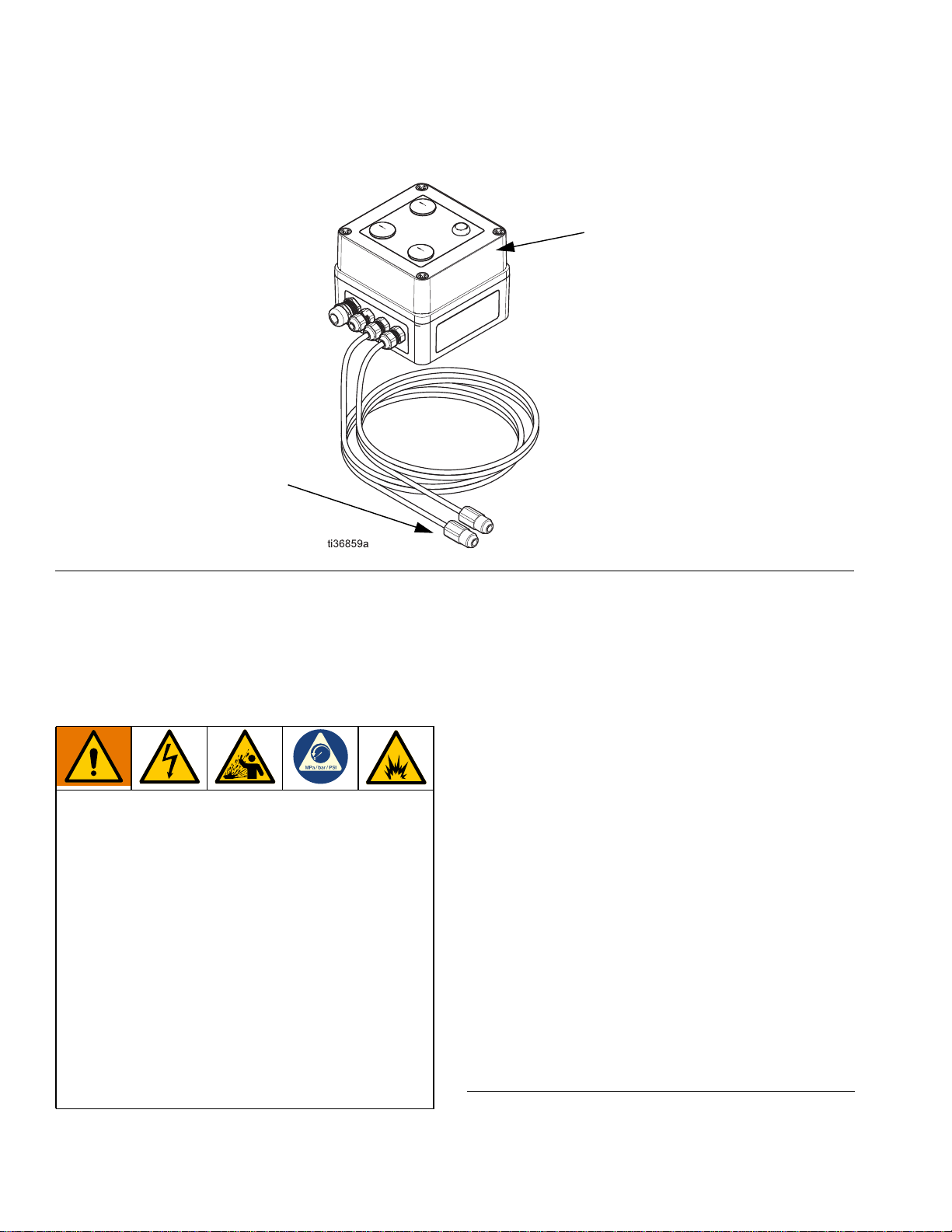
Connect Power to Control Box
The control box can be powered by 110 VAC or 240
VAC. AC power is connected to power supply PS1. See
FIG. 6.
1. If the cover has not already been removed for
sensor installation, unscrew four screws (C) and
remove the cover (D) from the control box. See FIG.
6.
2. Connect the line wire from your power source to
terminal L and the neutral wire to terminal N, labeled
on the power supply PS1. See FIG. 6.
NOTE: The power cord from your power source
may include a ground wire. The ground wire from
your power cord is not needed and should remain
unused. Clip off the unused ground wire.
3. Connect an external alarm, air valve, etc. to the
internal relay, if desired. The leak sensors can be
wired normally open (NO) or normally closed (NC).
See Technical Data for electrical specifications.
To wire the leak sensors NO, connect the output
signal wires to pins 11 and 14 on the CR3 terminal
strip. See FIG. 6.
To wire the leak sensors NC, connect the output
signal wires to pins 11 and 12 on the CR3 terminal
strip. See FIG. 6.
4. Reinstall the cover using the four screws.
Operation
During normal operation, the two green LED indicators
on the control box will be lit.
If an error or a diaphragm rupture or other leak occurs,
the green LED indicator corresponding to the sensor
that identified the leak will extinguish. The red FAULT
LED indicator will light. The relay will trip and change
state.
To clear the faulted state, press the reset button. See
FIG. 6. The relay will remain in faulted state until the
reset button is pressed. The green LED indicators will
relight if the corresponding sensors no longer detect liq-
uid.
Maintenance
Clean Sensors
Clean the sensors whenever the pump is disassembled
for cleaning or inspection.
NOTE: Always disconnect the power supply from the
control box or monitoring device prior to cleaning the
pump.
Test to ensure proper operation
1. Verify non-fault condition. With power to the control
box, verify that:
• the green LED indicators are lit
• the red FAULT LED indicator is extinguished
2. Verify operation of each sensor. Submerge each
sensor separately in the fluid being pumped. Verify
that:
• the green LED indicators are extinguished
• the red FAULT LED indicator is lit
3. Verify loss-of-power condition. Disconnect the
power supply from the control box. Verify that:
• the relay is set and performs the intended oper-
ation (i.e. shuts down the pump)
• all LED indicators are extinguished
All electrical wiring must be done by a qualified
electrician and comply with all local codes and
regulations.