Graco FOAM-CAT 200 Series Datasheet

Instructions – Parts List
GRACO INC.ąP.O. BOX 1441ąMINNEAPOLIS, MNą55440-1441
Copyright 1992, Graco Inc. is registered to I.S. EN ISO 9001
308219G
WARNING
FIRE, EXPLOSION, AND ELECTRIC
SHOCK HAZARD
The operating and safety features of this heater are
designed for use only with the Graco Foam-Catr
Heated Hoses: Models 218613 and 218614. To
reduce the risk of serious injury, never connect
other hoses to this heater.
CSA certified for use with 218613,
Series B, and 218614, Series B,
Heated Hoses.
Read warnings and instructions.
See page 2 for Table of Contents.
FOAM–CATRHEATER
For use ONLY with two component urethane fluids that are unfilled
and non–flammable.
3000 psi (21 MPa, 210 bar) Maximum Working Pressure
Temp. Class T2C (230_C) Maximum Fault Temperature
Nominal Operating Temperature: 95–158_F (35–70_C)
Ambient Temperature Range: 40–104_F (5–40_C)
This heater includes a heating element and an independent
temperature for each of two fluids, Isocyanate and Resin,
and an independent temperature control for the Foam–Catr
Heated Hose.
Foam-Catr200 15 lb/min
Model 235259 With Heated Hose Control
Series B 8880 Watt
Model 235839 Without Heated Hose Control
Series B 5100 Watt
Foam-Catr400 30 lb/min
Model 235260 With Heated Hose Control
Series B 13,980 Watt
Model 235840 Without Heated Hose Control
Series B 10,200 Watt
U.S. Patent No. 4,501,952; 4,725,713
U.K. Patent No. 2,138,601
Patented Bréveté 1986 Canada
01292

2 308219
Table of Contents
Symbols 2. . . . . . . . . . . . . . . . . . . . . . . . . . . . . . . . . . . . . .
Warnings 3. . . . . . . . . . . . . . . . . . . . . . . . . . . . . . . . . . . . .
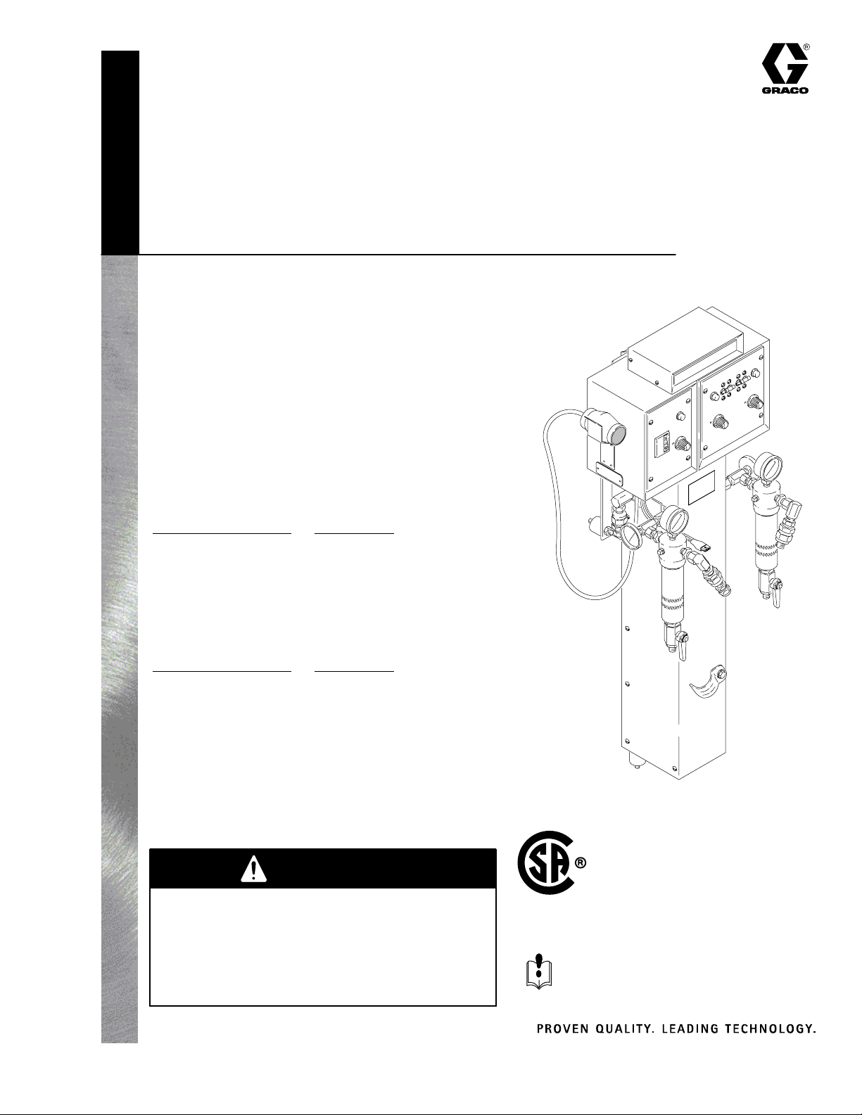
Introduction 5. . . . . . . . . . . . . . . . . . . . . . . . . . . . . . . . . .
Installation 6. . . . . . . . . . . . . . . . . . . . . . . . . . . . . . . . . . .
Pressure Relief Procedure 6. . . . . . . . . . . . . . . . . . .
Startup Check List 6. . . . . . . . . . . . . . . . . . . . . . . . . .
Typical Installation 7. . . . . . . . . . . . . . . . . . . . . . . . . .
Component Description 8. . . . . . . . . . . . . . . . . . . . . .
How to Size a Generator 10. . . . . . . . . . . . . . . . . . . .
Mount the Heater 10. . . . . . . . . . . . . . . . . . . . . . . . . .
Flush the Heater 11. . . . . . . . . . . . . . . . . . . . . . . . . . .
Connect the Electrical Service 12. . . . . . . . . . . . . . .
Ground the System 13. . . . . . . . . . . . . . . . . . . . . . . .
Prime the Heater 14. . . . . . . . . . . . . . . . . . . . . . . . . .
Connect the Hoses 15. . . . . . . . . . . . . . . . . . . . . . . . .
Prime the Hoses 15. . . . . . . . . . . . . . . . . . . . . . . . . . .
Adjust the Heater 16. . . . . . . . . . . . . . . . . . . . . . . . . .
Troubleshooting 17. . . . . . . . . . . . . . . . . . . . . . . . . . . . .
Heated Hose 17. . . . . . . . . . . . . . . . . . . . . . . . . . . . . .
Heater 18. . . . . . . . . . . . . . . . . . . . . . . . . . . . . . . . . . .
Electrical Resistance Checks 20. . . . . . . . . . . . . . . .
Setup 20. . . . . . . . . . . . . . . . . . . . . . . . . . . . . . . . . .
Heater Sensor Probe 20. . . . . . . . . . . . . . . . . . . . .
Thermostat 20. . . . . . . . . . . . . . . . . . . . . . . . . . . . .
Optional ATC (Ambient Temperature
Compensator) 22. . . . . . . . . . . . . . . . . . . . . . . . . . .
Heater Element 22. . . . . . . . . . . . . . . . . . . . . . . . .
Hose Sensor Simulator 22. . . . . . . . . . . . . . . . . . .
Hose Control Circuit Board 23. . . . . . . . . . . . . . . .
Triac 24. . . . . . . . . . . . . . . . . . . . . . . . . . . . . . . . . . .
Service 25. . . . . . . . . . . . . . . . . . . . . . . . . . . . . . . . . . . . . .
Triac 25. . . . . . . . . . . . . . . . . . . . . . . . . . . . . . . . . . . . .
Hi-Limit Thermostat 26. . . . . . . . . . . . . . . . . . . . . . . .
Heater Sensor Probe 27. . . . . . . . . . . . . . . . . . . . . . .
Heater Element 28. . . . . . . . . . . . . . . . . . . . . . . . . . . .
Circuit Board 30. . . . . . . . . . . . . . . . . . . . . . . . . . . . . .
Calibrating the Controls 32. . . . . . . . . . . . . . . . . . . . .
Hose Sensor Simulator, Optional ATC 34. . . . . . . .
Parts 36. . . . . . . . . . . . . . . . . . . . . . . . . . . . . . . . . . . . . . . .
Heater Assembly 36. . . . . . . . . . . . . . . . . . . . . . . . . .
Heated Hose Control 37. . . . . . . . . . . . . . . . . . . . . . .
Heater 38. . . . . . . . . . . . . . . . . . . . . . . . . . . . . . . . . . .
Electrical Schematics 41. . . . . . . . . . . . . . . . . . . . . . . . .
Dimensions 42. . . . . . . . . . . . . . . . . . . . . . . . . . . . . . . . . .
Technical Data 43. . . . . . . . . . . . . . . . . . . . . . . . . . . . . . .
Accessories 43. . . . . . . . . . . . . . . . . . . . . . . . . . . . . . . . .
Graco Standard Warranty 44. . . . . . . . . . . . . . . . . . . . .
Graco Information 44. . . . . . . . . . . . . . . . . . . . . . . . . . . .
Symbols
Warning Symbol
WARNING
This symbol alerts you to the possibility of serious
injury or death if you do not follow the instructions.
Caution Symbol
CAUTION
This symbol alerts you to the possibility of damage to
or destruction of equipment if you do not follow the
instructions.

3308219
WARNING
INSTRUCTIONS
EQUIPMENT MISUSE HAZARD
Equipment misuse can cause the equipment to rupture or malfunction and result in serious injury.
DThis equipment is for professional use only.
DRead all instruction manuals, tags, and labels before operating the equipment.
DUse the equipment only for its intended purpose. If you are uncertain about usage, call your Graco
distributor.
DDo not alter or modify this equipment. Use only genuine Graco parts and accessories.
DThe heater is very hot. Cool the heater before removing heater panels.
DDo not install a fluid shutoff device at the fluid outlet of the heater or filter as this will cause high
back pressure.
DCheck equipment daily. Repair or replace worn or damaged parts immediately.
DDo not exceed the maximum working pressure of the lowest rated system component. This equip-
ment has a 3000 psi (21 MPa, 210 bar) maximum working pressure.
DRoute hoses away from traffic areas, sharp edges, moving parts, and hot surfaces.
DTo avoid excessive heat buildup, never operate the hose when it is coiled.
DDo not use the hoses to pull the equipment.
DUse only Graco Foam-CatrHeated Hoses: Models 218613 and 218614.
DUse fluids and solvents that are compatible with the equipment wetted parts. Refer to the Techni-
cal Data section of all equipment manuals. Read the fluid and solvent manufacturer’s warnings.
DComply with all applicable local, state, and national fire, electrical, and safety regulations.
TOXIC FLUID HAZARD
Hazardous fluid or toxic fumes can cause serious injury or death if splashed in the eyes or on the skin,
inhaled, or swallowed.
DKnow the specific hazards of the fluid you are using.
DStore hazardous fluid in an approved container. Dispose of hazardous fluid according to all local,
state and national guidelines.
DAlways wear protective eyewear, gloves, clothing and respirator as recommended by the fluid and
solvent manufacturer.
DGraco does not manufacture or supply any of the reactive chemical components that may be used
in this equipment and is not responsible for their effects. Graco assumes no responsibility for loss,
damage, expense or claims for personal injury or property damage, direct or consequential, arising
from the use of such chemical components.
Continued on the next page.

4 308219
WARNING
INJECTION HAZARD
Spray from the gun, hose leaks, or ruptured components can inject fluid into your body and cause
extremely serious injury, including the need for amputation. Splashing fluid in the eyes or on the skin
can also cause serious injury.
DFluid injected into the skin might look like just a cut, but it is a serious injury. Get immediate medi-
cal attention.
DDo not point the spray gun at anyone or at any part of the body.
DDo not put your hand or fingers over the spray tip/nozzle.
DDo not stop or deflect leaks with your hand, body, glove or rag.
DDo not “blow back” fluid; this is not an air spray system.
DAlways have the trigger guard on the spray gun when spraying.
DBe sure the gun trigger safety operates before spraying.
DLock the gun trigger safety when you stop spraying.
DFollow the Pressure Relief Procedure on page 6 whenever you: are instructed to relieve pres-
sure; stop spraying; clean, check, or service the equipment; and install or clean the spray tip/
nozzle.
DTighten all fluid connections before operating the equipment.
DCheck the hoses, tubes, and couplings daily. Do not mend or repair any part of the hose assembly.
If the hose is damaged, replace it immediately.

5308219
WARNING
FIRE, EXPLOSION, AND ELECTRIC SHOCK HAZARD
Improper grounding, poor ventilation, open flames, or sparks can cause a hazardous condition and
result in fire, explosion, electric shock or other serious injury.
DGround the equipment and the object being sprayed. See Grounding on page 13.
DAll electrical wiring must be done by trained and qualified personnel and comply with all local codes
and regulations.
DDo not operate the heater with any heater panels removed.
DDisconnect the main power to the heater before removing heater panels or servicing the equip-
ment.
DKeep liquids away from the electrical components. Do not expose the heater to rain.
DDo not use the heater with flammable liquids, such as fluids having flash points below 200_F
(93_C).
DProvide fresh air ventilation to avoid the buildup of flammable fumes from solvents or the fluid
being sprayed.
DKeep the spray area free of debris, including solvent, rags, and gasoline.
DBefore operating this equipment, electrically disconnect all equipment in the spray area.
DBefore operating this equipment, extinguish all open flames or pilot lights in the spray area.
DDo not smoke in the spray area.
DDo not turn on or off any light switch in the spray area while operating or if fumes are present.
DDo not operate a gasoline engine in the spray area.
DIf there is any static sparking while using the equipment, stop spraying immediately. Identify and
correct the problem.
Introduction
Understanding how the Foam-CatrHeater functions
and how to adjust it properly for your application condi-
tions, is the key to easy operation and early detection
of possible equipment problems.
Read this manual and the manuals for all of the
components in your spray system thoroughly before
installing or operating the equipment.
Reference letters and numbers
Information on parts referenced with letters can usually
be found in the separate instruction manuals accompa-
nying those components.
Terms:
RES and ISO refer to the foam chemicals Resin and
Isocyanate, respectively.
Ambient Temperature is the surrounding air tempera-
ture.
ATC is the optional Ambient Temperature Compen-
sator feature of the Foam-Cat Heater. See page 9 for
further explanation.

6 308219
Installation
Pressure Relief Procedure
WARNING
INJECTION HAZARD
The system pressure must be manually
relieved to prevent the system from
starting or spraying accidentally. Fluid
under high pressure can be injected through the
skin and cause serious injury. To reduce the risk of
an injury from injection, splashing fluid, or moving
parts, follow the Pressure Relief Procedure
whenever you:
Dare instructed to relieve the pressure,
Dstop spraying,
Dcheck or service any of the system equipment,
Dor install or clean the spray tip/nozzles.
1. Lock the spray gun trigger safety.
2. Shut off the air to the feed pumps.
3. Turn off the electric motor switch in a hydraulic
system.
4. Turn off the air to the proportioning pump in an
air-powered system.
5. Close the gun manifold fluid valves.
6. Unlock the spray gun trigger safety.
7. Hold a metal part of the gun firmly to the side of a
grounded metal pail, then trigger the gun to relieve
pressure.
8. Lock the trigger safety again.
9. If possible, allow the heater to cool before opening
the drain valves. This prevents the Resin from
frothing.
10. Open both fluid filter drain valves; have a container
ready to catch the draining fluid.
11. If you suspect that the spray tip/nozzle or hose is
completely clogged, or that pressure has not been
fully relieved after following the steps above, very
slowly loosen the tip/nozzle retaining nut or hose
end coupling to relieve pressure gradually, then
loosen completely. Wear protective gloves to avoid
skin injection or burns. Now clear the tip/nozzle or
hose.
12. If you are working on any part of the heater, shut
off the main electrical power to the heater.
Startup Check List
nInstallation Steps Page
1. Fig. 1 shows a typical Foam-Catr
system. It is not an actual system
design. The particular type and
size system for your operation
must be custom designed for your
needs. For assistance in
designing a system, contact your
Graco distributor.
1
2. Read the Component Descrip-
tions to learn how each control
operates and to help you choose
the correct settings when you
operate the equipment.
8
3. When using a generator to power
your system, see page 10 to
determine the correct size.
10
4. Mount the heater in its permanent
location.
10
5. Flush the test oil from the heater. 11
6. Connect the electrical service. 12
7. Ground the system. 13
8. Prime the heater. 14
9. Connect the hoses. 15
10. Prime the hoses. 15
11. Adjust the heater. 16

7308219
Installation
1. Typical Installation
This drawing shows all the components and recommended accessories for a Foam-Cat 400 Sprayer, Model
235260, and the correct routing of all air and fluid hoses.
KEY
A Fluid Hose Displacement Pump
to Heater
B Heated Hose
C Main Air Supply Hose
D Air Manifold
E Optional ATC Sensor
F Air Hose, Heated Hose
107 Inlet Swivel Union
113 Fluid Outlet Union
Fig. 1
B
A
C
E
Air Dryer Kit
Feed
Pump
Bulldogr
Proportioning
Pump
Foam–Cat
Gun
Foam-Cat
Heated
Hose
F
113
107
D
01688

8 308219
Installation
2. Component Description
Fluid heater and control
The fluid heater (G) is actually two separate heaters,
one for Resin and one for Isocyanate. The heaters
have independent controls on the heater control panel
(116); see Control panel, below. Each heater also has
a thermometer (204).
A sensor probe (256 – see page 27) in each heater
senses fluid temperature and turns the heater element
on and off as needed. The heaters include a safety
limit thermostat, which shuts off the power if the fluid
gets too hot.
Heated hose control
(Models 235259 and 235260 only)
The heated hose control panel (317) controls power to
the heat tape in the heated hose assembly. The func-
tion of the heated hose is to maintain the proper fluid
temperature. The heated hose control panel is
discussed in the following Control Panel section.
Control panel
Each side of the heater, and the heated hose, has an
independent Temperature Set dial (K), a main power
circuit breaker (210 and 319) and an indicator light
(214 and 314) on the control panel.
The independent circuit breakers turn on or off the
main electrical power from the junction box. The
heated hose circuit breaker (319) (Models 235259 and
235260 only) includes a ground fault interrupter (GFI)
which shuts off the electrical power to the heat tape if it
detects a fault. The GFI is a 30 mA trip international
version that meets IEC 479.
NOTE: The circuit breakers use the international
symbols, Ifor ON and Ofor OFF.
Each side of the heater control (116) and the heated
hose control (317) has an indicator light (214 and 314)
on the control panel, which indicates when the heater
element is actually heating. The light blinks at about 1
second intervals. Its on–off time ratio indicates power
consumption.
The TEMP SET dial (K) is used to select the desired
fluid temperature. The range is approximately 95_F
(35_C) at MIN (minimum) to 158_F (70_C) at MAX
(maximum) settings.
Fig. 2 01294
317
319
314
214
210
K
111
G
116
204

9308219
Installation
2. Component Description (continued)
Thermometer gauges
Each heater has an independent thermometer (204).
Because of the effect on the surrounding metal
exposed to the air, the thermometer usually reads far
below the selected fluid temperature during no-flow
conditions. The thermometer reading is only valid
when fluid is flowing.
Fluid filter
A fluid filter (112) at the outlet of each heater removes
particles from the foam chemicals that could clog the
spray nozzle or distort the spray pattern. Refer to the
separate instruction manual, 307273, for maintenance
instructions.
Junction box
Electrical power to the Foam-Cat Heater is wired
directly to the junction box (233), which supplies power
to the heater and heated hose controls.
The optional Ambient Temperature Compensator
senses change in ambient temperature and increases
or decreases the amount of heat produced by the
heater or heated hose tape. The fluid is heated higher
on cold days than on hot days. The part number for
this accessory is 218564. See page 34 to install it.
How to use the OPTIONAL
Ambient Temperature Compensator (ATC)
Most fluid heaters produce, or output, just the amount
of heat selected on its TEMP SET dial, regardless of
ambient temperature changes during the day. So, in
order to maintain good foam development in outdoor
foam applications, the operator must continually adjust
the fluid temperature as ambient temperature changes.
The optional Foam-Cat Heater ATC feature automati-
cally checks and adjusts the fluid temperature. The
ATC Sensor (E–Fig. 1) which is designed to have no
effect on heater output at 80_F (27_C), senses
ambient temperature above or below 80_F (27_C) and
automatically raises or lowers the heater output.
With the Heater TEMP SET at 115_F (46_C), and at
an ambient temperature of 60_F (16_C), the heater
output automatically rises to 125_F (52_C). As the
ambient temperature rises to 80_F (27_C), no
compensation is needed and the fluid is heated to just
115_F (46_C). As the ambient temperature rises to
100_F (38_C), the heater output is automatically
lowered to 108_F (42_C).
Keep in mind these points when using the ATC:
1. An ATC is needed only when the ambient temper-
ature varies more than 20_above or below 80_F
(27_C).
2. At an ambient temperature of about 80_F (27_C),
the heater heats the fluid only to the selected
temperature.
Fig. 3 01294
233
112
204

10 308219
Installation
3. How to Size a Generator
for outdoor remote applications
Style Hose
Control
Model With Hydraulic
Pump Motor
WATTS (240 VAC)
Control Pump Motor 1 Phase 3 Phase
Foam–Cat 200 NO 235839 NO 5,100 7,650
Foam–Cat 200 YES 235259 NO 8,880 11,340
Foam–Cat 400 NO 235840 NO 10,200 15,300
Foam–Cat 400 YES 235260 NO 13,980 15,300
Foam–Cat 400 YES 235840 YES 13,980 15,300
Foam–Cat 400 YES 235260 YES 13,980 15,300
4. Mount the Heater
WARNING
ELECTRIC SHOCK HAZARD
To reduce the risk of electric shock, do
not expose the heater to rain.
If you have purchased the heater module separately,
bolt it securely to the Graco Pump Stand, part no.
217296 (see manual 307551) or to a wall. A mounting
hole diagram is on the back cover of manual 307551.
CAUTION
All critical air and fluid connections in the Foam-Cat
equipment are clearly labeled ISO or RES. Make
only ISO to ISO and RES to RES connections to
avoid fluid crossover which will permanently damage
the components.
CAUTION
If you are using a Freon injector, mount it down-
stream from the heater so it does not pass through
the heater.

11308219
Installation
5. Flush the Heater
WARNING
INJECTION HAZARD
To reduce the risk of serious injury,
follow the Pressure Relief Procedure
on page 6 before flushing the heater or
spray system and whenever you are instructed to
relieve pressure.
WARNING
FIRE AND EXPLOSION HAZARD
Before flushing, disconnect the electrical
power to the heater to reduce the risk of
static sparking, which can cause fire or
explosion.
CAUTION
The heater was tested in lightweight oil which was
left in to protect the parts during shipment. The oil
must be flushed or purged from the system to avoid
material contamination.
NOTES
1. Use a solvent that is recommended by your mate-
rial supplier, and be sure it is compatible with the
heater’s wetted parts.
2. Some material will be contaminated whether you
simply purge the oil from the heater or use a
solvent to thoroughly flush. Discard that material.
3. For long term shutdown or storage, flush with a
compatible solvent and then flush with a light-
weight oil. Leave the oil in the system to protect it
during shutdown.
4. Some material suppliers provide maintenance
services which include flushing and storage.
5. Never flush the hoses. It is very difficult to remove
all moisture from hoses which have been flushed,
and the moisture will contaminate the ISO and
RES.
Procedure
1. Relieve the pressure.
2. Disconnect the material hoses, if connected.
3. Remove the outlet fittings (X) from both fluid filter
outlet nipples (114).
4. Plug each outlet nipple (114) with a swivel (P/N
156173) and plug (P/N 101754). These parts are
shown exploded on the left side of Fig. 4 and
assembled on the right side of Fig. 4.
5. Connect your flushing system supply hose to the
IN port of one of the heaters.
6. Open the filter drain valve (111). Have a waste
container ready to catch the draining solvent.
7. Turn on the flushing system and use the lowest
possible pressure to flush the heater for several
seconds.
8. Shut off the flushing system and close the drain
valve.
9. Repeat this procedure for the other side of the
heater.
10. Continue the setup by connecting the electrical
service. When you are ready to prime the system,
the procedure on page 14 tells how to purge the
remaining solvent from the heater.
01689
Fig. 4
114
111
156173
101754
X

12 308219
Installation
6. Connect the Electrical Service
WARNING
ELECTRIC SHOCK HAZARD
To reduce the risk of serious injury,
including electric shock, all electrical
wiring must be done by trained and
qualified personnel and comply with all local codes
and regulations.
The electrical requirements for the heater and heated
hose controls and the wiring diagram are shown on the
inside cover of the junction box (233). Wire the heater
to your electrical service. Three jumper wires are
included.
This is the information on the label (205) under the
junction box cover.
38 Amps
38 Amps
38 Amps
22 Amps
22 Amps
22 Amps
22 Amps
16 Amps
16 Amps
L1
L2
L3
RES
HTR
5.1 Kw
ISO
HTR
5.1 Kw
HOSE
3.8 Kw
(max)
TB1
TB2
TB3
TB4
TB5
TB6
60 Amps
60 Amps
22 Amps
22 Amps
22 Amps
22 Amps
16 Amps
16 Amps
L1
L2
TB1
TB2
TB3
TB4
TB5
TB6
RES
HTR
5.1 Kw
ISO
HTR
5.1 Kw
HOSE
3.8 Kw
(max)
Model 235260
3 phase, 240 VAC
Model 235260
1 phase, 240 VAC
28 Amps
28 Amps
28 Amps
11 Amps
11 Amps
11 Amps
11 Amps
16 Amps
16 Amps
L1
L2
L3
RES
HTR
2.6 Kw
ISO
HTR
2.6 Kw
HOSE
3.8 Kw
(max)
TB1
TB2
TB3
TB4
TB5
TB6
Model 235259
3 phase, 240 VAC 38 Amps
38 Amps
11 Amps
11 Amps
11 Amps
11 Amps
16 Amps
16 Amps
Lx
Ly
TB1
TB2
TB3
TB4
TB5
TB6
RES
HTR
2.6 Kw
ISO
HTR
2.6 Kw
HOSE
3.8 Kw
(max)
Model 235259
1 phase, 240 VAC
38 Amps
38 Amps
38 Amps
22 Amps
22 Amps
22 Amps
22 Amps
L1
L2
L3
RES
HTR
5.1 Kw
ISO
HTR
5.1 Kw
TB1
TB2
TB3
TB4
Model 235840
3 phase, 240 VAC
Model 235260
1 phase, 240 VAC
44 Amps
44 Amps
22 Amps
22 Amps
22 Amps
22 Amps
L1
L2
RES
HTR
5.1 Kw
ISO
HTR
5.1 Kw
TB1
TB2
TB3
TB4
19 Amps
19 Amps
19 Amps
11 Amps
11 Amps
11 Amps
11 Amps
L1
L2
L3
RES
HTR
2.6 Kw
ISO
HTR
2.6 Kw
TB1
TB2
TB3
TB4
Model 235839
3 phase, 240 VAC
Model 235839
1 phase, 240 VAC
22 Amps
22 Amps
11 Amps
11 Amps
11 Amps
11 Amps
L1
L2
RES
HTR
2.6 Kw
ISO
HTR
2.6 Kw
TB1
TB2
TB3
TB4
FOAM–CAT 400
FOAM–CAT 200
FOAM–CAT 200
FOAM–CAT 400
FOAM–CAT 400
FOAM–CAT 400
FOAM–CAT 200
FOAM–CAT 200

13308219
Installation
7. Ground the System
WARNING
FIRE, EXPLOSION, AND ELECTRIC
SHOCK HAZARD
Before operating the heater, ground the
system as explained below. Also read
the section FIRE, EXPLOSION, AND
ELECTRIC SHOCK HAZARD on
page 5.
The following are minimum requirements for grounding
a basic system. Your system may include other equip-
ment or objects which must be grounded. Check your
local electrical code for detailed grounding instructions.
Your system must be connected to a true earth
ground.
1. Heater: wire the heater to a positively grounded
power supply. The heater is grounded through the
electrical wiring to a grounding screw (227) in the
junction box base (228). See Fig. 5.
Redundant grounding is recommended to further
reduce the risk of electric shock. The long lines of
the shielded-wire heated hose have higher than
normal capacitive leakage current to ground.
In a mobile installation, be sure the truck or trailer
is grounded to a true earth ground.
2. Pump: connect a ground wire and clamp to a true
earth ground as shown in your separate pump
manual.
3. Fluid hoses: use only grounded hoses with a
maximum of 500 ft. (150 m) combined hose length
to ensure grounding continuity.
4. Air hoses: use only Graco heated hose, which are
electrically conductive.
5. Spray gun: obtain grounding through connection to
a properly grounded fluid hose and pump.
6. Object being sprayed: ground according to local
code.
7. Fluid supply container: ground according to local
code.
8. All solvent pails used when flushing: ground
according to local code. Use only metal pails,
which are conductive. Do not place the pail on a
non-conductive surface, such as paper or card-
board, which interrupts the grounding continuity.
9. To maintain grounding continuity when flushing or
relieving pressure, always hold a metal part of the
gun firmly to the side of a grounded metal pail,
then trigger the gun.
Fig. 5
227
228

14 308219
Installation
8. Prime the Heater
CAUTION
Prime the heater and sprayer with fluid before turning
on the heater to reduce the risk of overheating and
burning out the heater element.
WARNING
FIRE AND EXPLOSION HAZARD
To reduce the risk of fire or explosion, do
not use the heater with flammable
liquids, such as fluids having flash points
below 200_F (93_C).
Specific priming instructions for the Foam-Cat
Sprayers are given in the sprayer manual, 307541 or
307542. If the heater is used in other spray systems,
use the following priming guidelines together with your
system priming instructions.
NOTE: Refer to Fig. 1, page 7 to identify the parts
mentioned in this section, except where noted other-
wise.
1. Be sure the heater has been flushed.
2. Close the feed pump air inlet valves.
3. Put a waste container under each heater drain
valve.
4. Be sure the heater and heated hose controls (K)
are turned OFF. See Fig. 6.
5. Open each pump’s fluid intake valve.
6. Open the main air shutoff valve.
7. Adjust the supply container air dryer equipment.
See the air dryer manual.
8. Open the feed pump air valve.
9. With the air or hydraulic power to the proportioning
pump set at a low pressure, turn on the pump.
10. When the solvent has been thoroughly purged
from both sides of the heater and ISO and RES
appear, shut off the proportioning pump and close
the heater drain valves.
11. Remove the swivel and plug from each filter fluid
outlet.
Fig. 6 01292
113
K
107
313

15308219
Installation
9. Connect the Hoses
WARNING
INJECTION HAZARD
To reduce the risk of overpressurizing
the heater and pump, which can cause
component rupture, serious injury or
property damage, follow these precautions:
1. Do not install any fluid shutoff device at the
fluid outlet (Y) of either the heater or filter
(112). See Fig. 7.
2. Use at least 15 ft. (4.5 m) of fluid hose
between the fluid outlet and any fluid control
device such as a shutoff valve, regulator, or
spray gun.
3. To reduce strain on the hose near the hose
couplings, route the heated hoses through the
clamp (126) on the front of the heater.
4. Turn hose heat on 15 minutes before turning
pump on to reduce heat expansion pressure.
1. Connect the fluid supply hoses from the displace-
ment pump to the proper fluid inlet union (107) on
each side of the heater. See Fig. 7.
2. Connect the fluid dispense hoses of the heated
hose assembly to the fluid outlet union (113) of
each fluid filter.
3. Connect a main air supply hose (C) to the manifold
(D) on the side of the pump stand. See Fig. 1,
page 7.
4. Connect the heat tape connector of the heated
hose assembly to the heated hose control box
cable (313). See Fig. 7.
5. Connect the heated hose assembly air hose (F) to
the jumper hose from the air manifold (D). See
Fig. 1.
10. Prime the Hoses
1. Tightly close the spray gun fluid valves and discon-
nect the gun from its manifold. Refer to the gun
manual.
2. Hold each side of the gun manifold over a sepa-
rate grounded waste container, open the fluid
valves and allow fluid to flow out until all air is
purged. Close fluid valves. See the gun manual.
3. Check for fluid connection leaks. Relieve fluid
pressure and correct.
4. Increase pressure and check again for leaks.
5. Insulate hose connections and install the abrasion
cover as instructed in manual 307544.
01691
Fig. 7
Y
112
113
107
313
111
126

16 308219
Installation
11. Adjust the Heater
1. Measure the incoming voltage on the junction box
power in terminal block from pins 1 to 2, pins 3 to
4, and pins 5 to 6. See Fig. 10 or 11, pages 21 and
23. Voltage must read 200 to 240 VAC rms
between each set of pins.
2. Set all three Temperature Set dials (K) to CAL.
See Fig. 8.
3. Turn the circuit breakers (210 and 319) to I(ON).
See Fig. 8.
4. Check that the input voltage is still correct.
5. The heater lamps should blink within 10 seconds
after turning on the circuit breakers. With fluid
flowing only, check the heater thermometers (204)
regularly and manually adjust the fluid temperature
as needed. See Fig. 8.
6. The heated hose control lamp should start blinking
soon after turning on the circuit breaker. The
duration of ON versus OFF time indicates power
applied.
NOTE: If the lamps do not start blinking in the time
specified above, check for possible problems and
solutions in the Troubleshooting guide, starting on
page 18.
7. If using a heated hose control, test the Ground
Fault Interrupter (GFI) daily. To test, depress the
button (N). See Fig. 8. If the circuit breaker shuts
off, the GFI is working properly.
01691
Fig. 8
K
210
319
N
204

17308219
Troubleshooting
WARNING
To reduce the risk of injury from burns or electric shock, never operate the heater with any heater shield or
panel removed. Disconnect the main electrical power to the heater before removing any heater panels.
To reduce the risk of serious injury, including injection, follow the Pressure Relief Procedure on page 6 before
checking or repairing any part of the heater or spray system.
NOTE: Try the recommended solutions in the order given for each problem to avoid unnecessary repairs.
Heated Hose
Problem Cause Solution
Heated Hose Control indicator
lamp stays on
Faulty triac (281) Check triac wiring. See Fig. 13, page 25.
Faulty circuit board (223 or 306) Replace. See page 30.
Faulty Hose Sensor Simulator (304) Be sure simulator is firmly plugged into circuit
board.
Check simulator resistance. See page 23.
Hose Sensor Simulator (304) not
plugged in
Plug in.
Heated Hose Control indicator
lamp stays off
Heated hose not plugged into control
box
Check, plug in.
Wiring or voltage problem Check the wiring and the voltage:
200–240 VRMs during fluid flow and at stall.
See Adjust the Heater, Step 1, page 16.
Faulty circuit board Replace. See page 30.
Hose thermostat is bad Check. See manual 307544.
Hose temperature fluctuates Hose Sensor Simulator (304) out of
calibration
Be sure simulator is firmly plugged into circuit
board. Check calibration. See page 34.
Faulty Hose Sensor Simulator (304) Replace. See page 34.

18 308219
Troubleshooting
Heater
Problem Cause Solution
Heater Control indicator lamp stays
on
Flow rate too high to maintain set
temperature
Decrease flow rate; using smaller orifice nozzle
reduces flow rate.
Release gun trigger; lights should go off in a
few seconds.
Maximum flow rates are:
Foam-Catr200: 15 lb/min (6.8 kg/min)
Foam-Catr400: 30 lb/min (13.5 kg/min)
Faulty Sensor Probe (256) Check the following for both sides of heater:
1. Probe connector is aligned properly into all
3 male pins of circuit board.
2. Probe protrudes 1.44” (36 mm) from
manifold. See Fig. 16, page 27.
3. Check resistance. See page 20.
P1 connector unplugged; see
drawing to the left
Plug in.
Check resistance. See page 20.
Faulty Triac Check triac wiring. See Fig. 12, page 24.
Check resistance. See page 24.
The ATC, if used, is not plugged in Be sure ATC connector, if used, is properly
plugged into circuit board.
Check resistance. See page 22.
Circuit board out of calibration See page 32. Calibration procedure is included
in replacement procedure.
Sensor Probe (256) not plugged in Plug in. See page 27.
Heater Control indicator lamp
stays off – no heat.
Thermostat(s) (252) open (normally
closed)
Reset thermostat by pushing reset button. See
Fig. 14, page 26.
Triac wires not connected properly Check triac detail. See Fig. 13, page 25.
TEMP SET dial wires not connected Check wiring. See Fig. 10, page 21.
Faulty circuit board Replace. See page 30.
AC power wiring or voltage problem Check for 200–240 VRMs. See Adjust the
Heater, Step 1, page 16.
Elements burned out or not
plugged in
Check element resistance. See page 22.

19308219
Troubleshooting
Problem Cause Solution
Temperature erratic or inaccurate Sensor probe (256) out of position Probe must protrude 1.44” (36 mm) from
manifold. See Fig. 16, page 27.
Indicator light should go out within 5 seconds of
shutting gun off after flowing.
Heater out of calibration Calibrate controls. See page 32.
Improper incoming voltage Check the wiring and the voltage:
200–240 VRMs during fluid flow and at stall.
See Adjust the Heater, Step 1, page 16.
One thermostat open (normally
closed), Model 235260 & 235840
only
Reset thermostat by pushing reset button. See
Fig. 14, page 26.
Faulty sensor probe (256) Check resistance. See page 20.
Replace. See page 27.
Large pressure difference between
ISO and RES side, For example:
Thermostat(s) (252) open Reset thermostat by pushing reset button. See
Fig. 14, page 26.
600 psi (4.2 MPa, 42 bar) ISO
1000 psi (7 MPa, 70 bar) RES Fluid on high pressure side is too
thick
Increase heater temperature on high pressure
side to reduce viscosity, which should level the
pressure, OR lower the temperature on the low
pressure side.
WARNING: As this problem
can be caused by clogged or
blocked parts, take special care
and follow the Pressure Relief
Procedure page 6 before
Gun nozzle impingers clogged or
damaged
Clean nozzle. Using an oversized cleanout pin
or damaging nozzle during cleaning may
increase impinger hole size and cause an
imbalance of fluid. See gun manual 307546.
Procedure, page 6, before
checking, cleaning or clearing parts
to help reduce the risk of serious
injury, including injection.
Blocked filters Check outlet filter (112; also see manual
307273).
Check gun check valve screen. See gun
manual 307546.
Clogged hoses Flush clean, if possible, or replace hose. Use
and clean filters regularly. Don’t allow mixed
fluid to back up into hoses.
Fluid supply low or empty Refill; prime system to remove air.
Fluid pump or hose connections
leaking
Check for leaks and repair or tighten as
needed. See pump manual also.

20 308219
Troubleshooting Electrical Resistance Checks
WARNING
To reduce the risk of serious injury, including fluid
injection or electric shock:
1. Follow the Pressure Relief Proce-
dure on page 6 before checking or
adjusting any part of the system or
any component and whenever you
are instructed to relieve pressure.
2. Disconnect the main electrical power
to the heater before removing any
heater panels.
Measuring the resistance of a part helps determine if it
is working properly. If you get a measurement other
than those given in the following procedures, replace
the faulty part.
Setup
1. Relieve the pressure, and shut off the main power
to the heater.
2. Remove the appropriate control panels.
3. Determine the approximate temperature of the
part; if the heater was operated recently, the
temperature will be high.
4. To remove wires, use the accessory tool, P/N
110968 or a 3/16 in. wide screwdriver. Insert the
tool into the slot below each wire on the terminal
block, push the tool away from the wire and pull
out the wire. See Fig. 9.
5. To reconnect the wires, push the tool into the slot,
slide in the wire and release the tool.
Fig. 9 01698
Tool 110968
Heater Sensor Probe
1. Follow the previous Setup instructions.
2. Remove the heater control panel (216). See Fig.
13, page 25.
3. Unplug the connector P1 at position J2 on the
heater circuit board in question. See Fig. 10.
4. Check the resistance across the two outside
terminals of connector P2. The resistance should
be:
45K to 55K ohms at 77_F (26_C), or
10K to 20K ohms at 120_F (49_C)
5. To replace the sensor probe (256), see page 22.
Thermostat (normally closed)
1. Follow the previous Setup instructions.
2. To check continuity from inside the wiring junction
box, remove the wires from connector T1 and
check continuity across the wires. See Fig. 10.
3. To check continuity at the thermostat, remove the
front heater element shroud (238). Check for
continuity across the terminals at each switch, with
one lead disconnected and after pushing the reset
button. See Fig. 13, page 25.
4. If there is no continuity, replace the thermostat.
See page 26.
This manual suits for next models
15
Table of contents
Other Graco Heater manuals
Popular Heater manuals by other brands

Belson
Belson ESH-02 owner's manual

Master
Master MH-40-GFA User's manual & operating instructions

Tectro
Tectro 36874 operating manual

Evinox
Evinox ModuSat XR Installation, commissioning and servicing instructions

AENO
AENO AGH0001S-IT Installation and operation manual

Aqua-Hot
Aqua-Hot 200 Series Service manual