Graco SaniForce 26B065 User manual

3A8940A
EN
Instructions
SaniForce® Heater
For heating fluids in ultra-high purity (sanitary) environments. Not approved for use in
explosive atmospheres or hazardous (classified) locations. For professional use only.
60 psi (0.41 MPa, 4.1 bar) Maximum Working Pressure
203°F (95°C) Maximum Operating Temperature
Important Safety Instructions
Read all warnings and instructions in
this manual before using the
equipment. Save these instructions.

2 3A8940A
Contents
Models and Approvals . . . . . . . . . . . . . . . . . . . . . . . 3
Warnings . . . . . . . . . . . . . . . . . . . . . . . . . . . . . . . . . . 4
Description . . . . . . . . . . . . . . . . . . . . . . . . . . . . . . . . 7
General Information . . . . . . . . . . . . . . . . . . . . . . . . . 7
Typical Installation . . . . . . . . . . . . . . . . . . . . . . . . . . 7
Installation. . . . . . . . . . . . . . . . . . . . . . . . . . . . . . . . . 8
Mount the Equipment . . . . . . . . . . . . . . . . . . . . . 8
Grounding . . . . . . . . . . . . . . . . . . . . . . . . . . . . . . 9
Connect Supply Wiring . . . . . . . . . . . . . . . . . . . 10
Before First Use . . . . . . . . . . . . . . . . . . . . . . . . . 11
Operation. . . . . . . . . . . . . . . . . . . . . . . . . . . . . . . . . 12
Pressure Relief Procedure . . . . . . . . . . . . . . . . . 12
Before Each Use . . . . . . . . . . . . . . . . . . . . . . . . 12
Start and Adjust the Equipment. . . . . . . . . . . . . 13
Shutdown. . . . . . . . . . . . . . . . . . . . . . . . . . . . . . 13
Maintenance . . . . . . . . . . . . . . . . . . . . . . . . . . . . . . 14
Establish a Preventive Maintenance Schedule . 14
Flush the Equipment . . . . . . . . . . . . . . . . . . . . . 14
Store the Equipment . . . . . . . . . . . . . . . . . . . . . 14
Routine Cleaning of Fluid Contact Section . . . . 15
Recycling and Disposal . . . . . . . . . . . . . . . . . . . . . 15
End of Product Life . . . . . . . . . . . . . . . . . . . . . . 15
Troubleshooting . . . . . . . . . . . . . . . . . . . . . . . . . . . 16
Repair. . . . . . . . . . . . . . . . . . . . . . . . . . . . . . . . . . . . 19
Prepare Equipment for Repair . . . . . . . . . . . . . . 19
Replace Heating Element. . . . . . . . . . . . . . . . . . 19
Parts . . . . . . . . . . . . . . . . . . . . . . . . . . . . . . . . . . . . . 20
Kits and Accessories . . . . . . . . . . . . . . . . . . . . . . . 21
Part Kits . . . . . . . . . . . . . . . . . . . . . . . . . . . . . . . 21
Accessory Kits . . . . . . . . . . . . . . . . . . . . . . . . . . 21
Torque Instructions. . . . . . . . . . . . . . . . . . . . . . . . . 22
Torque Sequence . . . . . . . . . . . . . . . . . . . . . . . . . . 22
Electrical Schematics. . . . . . . . . . . . . . . . . . . . . . . 23
Wiring Diagram. . . . . . . . . . . . . . . . . . . . . . . . . . 23
Wiring for 208 V and 240 V Models . . . . . . . . . . 24
Wiring for 400 V Models. . . . . . . . . . . . . . . . . . . 25
Wiring for 480 V Models. . . . . . . . . . . . . . . . . . . 26
Performance Charts . . . . . . . . . . . . . . . . . . . . . . . . 27
Performance Charts for 12 kW Models . . . . . . . 27
Performance Charts for 18 kW Models . . . . . . . 27
Performance Charts for 24 kW Models . . . . . . . 28
Dimensions . . . . . . . . . . . . . . . . . . . . . . . . . . . . . . . 29
Technical Specifications . . . . . . . . . . . . . . . . . . . . 30
California Proposition 65 . . . . . . . . . . . . . . . . . . . . 30
Graco Standard Warranty. . . . . . . . . . . . . . . . . . . . 32

Models and Approvals
3A8940A 3
Models and Approvals
Record the model part number found on your
equipment identification plate (ID) to assist you when
ordering replacement parts:
__________________________________________
ID
Part Description Approvals
26B065 24 kW, 208 V heater
Heating elements in all models are UL Recognized to UL 1030
and CSA C22.2 No. 72.
26B756 24 kW, 240 V heater
26B757 24 kW, 400 V heater
26B758 24 kW, 480 V heater
26B759 18 kW, 208 V heater
26B760 18 kW, 240 V heater
26B761 18 kW, 400 V heater
26B762 18 kW, 480 V heater
26B763 12 kW, 208 V heater
26B764 12 kW, 240 V heater
26B765 12 kW, 400 V heater
26B766 12 kW, 480 V heater

Warnings
4 3A8940A
Warnings
The following warnings are for the setup, use, grounding, maintenance, and repair of this equipment. The
exclamation point symbol alerts you to a general warning and the hazard symbols refer to procedure-specific risks.
When these symbols appear in the body of this manual or on warning labels, refer back to these Warnings.
Product-specific hazard symbols and warnings not covered in this section may appear throughout the body of this
manual where applicable.
DANGER
SEVERE ELECTRIC SHOCK HAZARD
This equipment can be powered by more than 240 V. Contact with this voltage will cause death or
serious injury.
• Turn off and disconnect power at main switch before disconnecting any cables and before servicing
equipment.
• This equipment must be grounded. Connect only to grounded power source.
• All electrical wiring must be done by a qualified electrician and comply with all local codes and
regulations.
• Do not expose to rain. Store indoors.
WARNING
BURN HAZARD
Equipment surfaces and fluid that is heated can become very hot during operation. To avoid severe
burns:
• Do not touch hot fluid or equipment.
FIRE AND EXPLOSION HAZARD
Flammable fumes, such as solvent and paint fumes, in work area can ignite or explode. Paint or
solvent flowing through the equipment can cause static sparking. To help prevent fire and explosion:
• Use equipment only in well-ventilated area.
• Eliminate all ignition sources; such as pilot lights, cigarettes, portable electric lamps, and plastic
drop cloths (potential static sparking).
• Ground all equipment in the work area. See Grounding instructions.
• Never spray or flush solvent at high pressure.
• Keep work area free of debris, including solvent, rags and gasoline.
• Do not plug or unplug power cords, or turn power or light switches on or off when flammable fumes
are present.
• Use only grounded lines.
• Hold gun firmly to side of grounded pail when triggering into pail. Do not use pail liners unless they
are anti-static or conductive.
•Stop operation immediately if static sparking occurs or you feel a shock. Do not use equipment
until you identify and correct the problem.
• Keep a working fire extinguisher in the work area.

Warnings
3A8940A 5
EQUIPMENT MISUSE HAZARD
Misuse can cause death or serious injury.
• Do not operate the unit when fatigued or under the influence of drugs or alcohol.
• Do not exceed the maximum working pressure or temperature rating of the lowest rated system
component. See Technical Specifications in all equipment manuals.
• Use fluids and solvents that are compatible with equipment wetted parts. See Technical
Specifications in all equipment manuals. Read fluid and solvent manufacturer’s warnings. For
complete information about your material, request Safety Data Sheets (SDSs) from distributor or
retailer.
• Do not leave the work area while equipment is energized or under pressure.
• Turn off all equipment and follow the Pressure Relief Procedure when equipment is not in use.
• Check equipment daily. Repair or replace worn or damaged parts immediately with genuine
manufacturer’s replacement parts only.
• Do not alter or modify equipment. Alterations or modifications may void agency approvals and
create safety hazards.
• Make sure all equipment is rated and approved for the environment in which you are using it.
• Use equipment only for its intended purpose. Call your distributor for information.
• Route lines and cables away from traffic areas, sharp edges, moving parts, and hot surfaces.
• Do not kink or over bend lines or use lines to pull equipment.
• Keep children and animals away from work area.
• Comply with all applicable safety regulations.
THERMAL EXPANSION HAZARD
Fluids subjected to heat in confined spaces, including lines, can create a rapid rise in pressure due to
the thermal expansion. Over-pressurization can result in equipment rupture and serious injury.
• Open a valve to relieve the fluid expansion during heating.
• Replace lines proactively at regular intervals based on your operating conditions.
WARNING

Warnings
6 3A8940A
PRESSURIZED EQUIPMENT HAZARD
Fluid from the equipment, leaks, or ruptured components can splash in the eyes or on skin and cause
serious injury.
•Follow the Pressure Relief Procedure when you stop spraying/dispensing and before cleaning,
checking, or servicing equipment.
•Tighten all fluid connections before operating the equipment.
•Check hoses, tubes, and couplings daily. Replace worn or damaged parts immediately.
PERSONAL PROTECTIVE EQUIPMENT
Wear appropriate protective equipment when in the work area to help prevent serious injury, including
eye injury, hearing loss, inhalation of toxic fumes, and burns. Protective equipment includes but is not
limited to:
• Protective eyewear, and hearing protection.
• Respirators, protective clothing, and gloves as recommended by the fluid and solvent manufacturer.
WARNING

Description
3A8940A 7
Description
The SaniForce Heater is an electric heating system to
heat fluids in ultra-high purity (sanitary) environments.
This heating system may be used with aggressive
fluids, such as deionized water or acids, while
maintaining the purity of those process fluids.
General Information
•Typical installations are shown in FIG. 1 and FIG. 2.
The figures are only guides for selecting and
installing system components. Contact your Graco
distributor for assistance in planning a system to
suit your needs.
•Always use genuine Graco parts and accessories.
•Reference numbers and letters in parentheses refer
to the callouts in the figures.
Typical Installation
FIG. 1: Horizontally Mounted Typical Installation FIG. 2: Vertically Mounted Typical Installation
Key:
A
D
B
E
C
F
F
C
E
A
D
J
HG
B
H
G
J
AFluid inlet port
BFluid outlet port
CElectrical wiring port
DFlexible, conductive fluid inlet line
EFlexible, conductive fluid outlet line
F* Thermocouple wire
GPressure relief valve (required, not supplied)
HFluid shutoff valve (required, not supplied)
JFluid drain valve (required, not supplied)
*Connect to a temperature controller (not shown;
required, not supplied).

Installation
8 3A8940A
Installation
Mount the Equipment
The equipment may be mounted vertically or
horizontally. See FIG. 1 and FIG. 2.
Follow the Pressure Relief Procedure, page 12,
before moving the equipment.
1. Ensure that the mounting surface is level and can
support the weight of the equipment, fluid, lines,
and accessories, as well as the stress caused
during operation.
2. For all mountings, be sure the equipment is firmly
secured with fasteners through the mounting feet to
the mounting surface. See Dimensions, page 29,
and FIG. 3.
NOTE: For ease of operation and service, mount the
equipment so the electrical wiring port (C), fluid inlet
port (A), and fluid outlet port (B)are easily accessible.
NOTE: To ensure fluid contact with heating elements,
mount the equipment so that the fluid outlet port (B) is
above the fluid inlet port (A). See Typical Installation,
page 7.
NOTE: A pressure relief valve is required. Install the
pressure relief valve (G) downstream from the
equipment, as close to the outlet port (B) as possible.
See FIG. 1 and FIG. 2.
FIG. 3: Mounting Holes
To prevent fire and explosion, locate equipment
away from all flammable and combustible materials.
To avoid burns, mount in a location where operators
will not come in contact with hot metal surfaces of
the equipment. Insulate and label lines and
components exiting equipment that may become
hot.
NOTICE
To prevent equipment damage, use all fastener holes
to firmly secure all feet to the mounting location.
mounting feet

Installation
3A8940A 9
Grounding
Ground the heater: Ground the heater to a properly
grounded power source. Connect the ground wire to
the ground terminal. See FIG. 5.
1. Ensure that the electrical disconnect (AA) to the
heater is shut off and locked.
FIG. 4: Electrical Disconnect
2. Remove the fasteners (9), washers (8), cap (7), and
o-ring (6) to access the electrical wiring
compartment.
3. Insert the supply ground wire through the electrical
wiring port (C).
4. Connect one end of the supply ground wire to the
ground terminal (10a).
NOTE: The ground terminal (10a) is a 1/4-20
thread. Torque to 75 in-lb (8.5 N•m).
5. Connect the other end of the supply ground wire to
a true earth ground.
6. Install the o-ring (6), cap (7), washers (8), and
fasteners (9). Torque fasteners (9) to 20 in-lb
(2.2 N•m). See Torque Sequence, page 22.
FIG. 5: Ground Terminal
Ground the fluid lines: Use only electrically conductive
lines with a maximum of 500 ft. (150 m) combined line
length to ensure grounding continuity. Check electrical
resistance of lines. If total resistance to ground exceeds
25 megohms, replace line immediately.
Ground the fluid supply and receiving containers:
Follow local codes and regulations.
Ground solvent pails used when flushing: Follow
local codes and regulations. Use only conductive metal
pails, placed on a grounded surface. Do not place the
container on a nonconductive surface, such as paper or
cardboard, which interrupts grounding continuity.
The equipment must be grounded to reduce the risk
of static sparking and electric shock. Electric or static
sparking can cause fumes to ignite or explode.
Improper grounding can cause electric shock.
Grounding provides an escape wire for the electric
current.
AA 10a 1
Torque to 75 in-lb (8.5 N•m).
1
2
2
Torque to 20 in-lb (2.2 N•m).
C
9
8
7
6

Installation
10 3A8940A
Connect Supply Wiring
Ensure the equipment is connected to a temperature
controller that limits the operating temperature to 203°F
(95°C) or less.
See Technical Specifications, page 30, for electrical
requirements.
1. Ensure that the electrical disconnect (AA) to the
heater is shut off and locked.
FIG. 6: Electrical Disconnect
2. Remove the fasteners (9), washers (8), cap (7), and
o-ring (6) to access the electrical wiring
compartment.
3. Insert electrical wires through the electrical wiring
port (C).
4. Connect wires to terminals. See Electrical
Schematics, starting on page 23.
NOTE: Conductors and terminals used for supply
connection must be suitable for 221°F (105°C) or
greater.
NOTE: Heater terminals are 1/4-20 thread. Torque
to 75 in-lb (8.5 N•m).
5. Install the o-ring (6), cap (7), washers (8), and
fasteners (9). Torque fasteners (9) to 20in-lb
(2.2 N•m). See Torque Sequence, page 22.
FIG. 7
Connect Thermocouple
A Type J thermocouple is permanently installed in the
system. Connect the thermocouple wire (F) to your
temperature controller (required, not supplied).
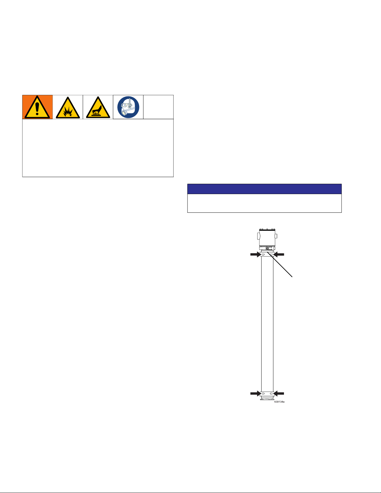
Install a second temperature sensor (required, not
supplied) as close to the fluid outlet port as possible to
measure fluid outlet temperature.
Connect Over-Current Protective Devices
Prior to powering on, install external over-current
protective devices (required, not supplied) to the
equipment. See Technical Specifications, page 30, for
electrical requirements.
All electrical wiring must be done by a qualified
electrician and comply with all local codes and
regulations.
NOTICE
To prevent voltage fluctuations that may result in
equipment damage, use the proper temperature
controller, voltage, wiring, fusing, sensors, and sizing
of electrical connections for your equipment.
NOTICE
To prevent equipment damage, do not torque
terminal nuts more than 75 in-lb (8.5 N•m).
AA
NOTICE
Do not exceed the maximum operating temperature
of 203°F (95°C). Operating the equipment outside of
these conditions can result in premature heater
failure, heater short, or potentially hazardous heater
burnout.
1
Torque terminal nuts to 75 in-lb (8.5 N•m).
1
2
2
Torque to 20 in-lb (2.2 N•m).
C
9
8
7
6F

Installation
3A8940A 11
Before First Use
Tighten Fasteners
Before using the equipment for the first time, check and
torque all fasteners. See Torque Instructions, page 22.
After the first day of operation, re-torque the fasteners.
NOTE: Be sure to use a compatible liquid thread sealant
on all male threads. Securely tighten all fittings and
plugs. Re-torque all fasteners before starting the
equipment. See Torque Instructions, page 22.
Tighten Connections
Check and tighten all fluid connections before operating
the equipment. Replace worn or damaged parts as
needed.
Flush the Equipment
The equipment was tested with a glycerin and water
solution. If glycerin or water could contaminate your
fluid, flush the equipment with a compatible solvent
before using the equipment. Follow Flush the
Equipment, page 14.
NOTICE
To avoid equipment damage, do not over-torque the
fasteners on the equipment.
NOTICE
Firmly tighten all connections to avoid leaks and
damage to equipment parts.

Operation
12 3A8940A
Operation
Pressure Relief Procedure
For pressure relief procedures specific to your pump,
see your pump manual.
Follow the Pressure Relief Procedure whenever
you see this symbol.
1. Turn off and disconnect power to the heater.
2. Circulate fluid through the system to cool the
heated fluid and heater.
3. Turn off the pump and disconnect power to the
system.
4. Close your system fluid inlet valve.
5. Open outbound fluid dispense valve to relieve fluid
pressure from the system.
6. Open the fluid drain valve (J).
7. Drain the fluid into a grounded waste container to
relieve pressure.
8. Open any fluid drain valves in the system.
9. Leave the drain valve open until you are ready to
pressurize the system.
Before Each Use
Tighten Fasteners
Check and tighten all fasteners before operating the
equipment. Re-torque as needed. See Torque
Instructions, page 22.
NOTE: Be sure to use a compatible liquid thread sealant
on all male threads. Securely tighten all fittings and
plugs. Re-torque all fasteners before starting the
equipment. See Torque Instructions, page 22.
Tighten Connections
Check and tighten all fluid connections before operating
the equipment. Replace worn or damaged parts as
needed.
Flush the Equipment
Flush the equipment before each use. See Flush the
Equipment, page 14.
NOTICE
Do not apply power to the equipment without a
minimum flow of 0.5 gpm (1.89 lpm) and a minimum
outlet pressure of 20 psi (1.38 bar, 0.14 MPa), and
do not exceed the maximum operating temperature
of 203°F (95°C). Operating the equipment outside of
these conditions can result in premature heater
failure, heater short, or heater burnout.
This equipment stays pressurized until pressure is
manually relieved. To help prevent serious injury from
pressurized fluid, such as splashing fluid, follow the
Pressure Relief Procedure when you stop dispensing
and before cleaning, checking, or servicing the
equipment.
NOTICE
To avoid equipment damage, do not over-torque the
fasteners on the equipment.
NOTICE
Firmly tighten all connections to avoid leaks and
damage to equipment parts.

Operation
3A8940A 13
Start and Adjust the Equipment
See your separate temperature controller manual for
directions on operating the system.
Determine Heater Temperature
For maximum equipment life, use the lowest
temperature setting needed.
Shutdown
1. Perform Flush the Equipment, page 14.
2. Perform Pressure Relief Procedure, page 12.
3. Verify that the equipment is turned off and power to
the system is disconnected.
4. Allow equipment to cool.
Thermal expansion can cause over-pressurization,
resulting in equipment rupture and serious injury from
splashing fluids. Do not pressurize the system when
preheating the equipment.
NOTICE
Heated equipment must always contain fluid when
the power is on. Never turn on heat zone switches
while equipment is empty. Heating empty equipment
may cause equipment damage.
NOTICE
Operating the equipment at its highest setting, 203°F
(95°C), for long periods of time decreases the
equipment life. Temperatures higher than necessary
may also cause the fluid to dry out, resulting in a
poor finish and clogged equipment.

Maintenance
14 3A8940A
Maintenance
Establish a Preventive
Maintenance Schedule
Establish a preventive maintenance schedule based on
the equipment service history.
Inspect the Equipment
Regularly inspect the equipment for worn or damaged
parts. Replace worn or damaged parts as needed.
Torque Fasteners
Regularly check and torque all fasteners. See Torque
Instructions, page 22.
NOTE: Be sure to use a compatible liquid thread sealant
on all male threads. Securely tighten all fittings and
plugs. Re-torque all fasteners before starting the
equipment. See Torque Instructions, page 22.
Tighten Connections
Check and tighten all fluid connections before operating
the equipment. Replace worn or damaged parts as
needed.
Flush the Equipment
• Before flushing, ensure the equipment is off and
power to the system is disconnected.
• Flush before fluid can dry in the equipment, at the
end of the day, before storing, and before repairing
equipment.
• Flush at the lowest pressure possible. Check
connectors for leaks and tighten as necessary.
•Flush with cool water or a fluid that is compatible
with the fluid being dispensed and the equipment
wetted parts.
1. Perform Pressure Relief Procedure, page 12.
2. Set your pump to the lowest possible fluid
pressure, and start the pump.
3. Run the pump until clean solvent dispenses.
Store the Equipment
Always relieve the pressure and flush the equipment
before storing the equipment for any length of time.
1. Perform Flush the Equipment, page 14.
2. Perform Pressure Relief Procedure, page 12.
NOTICE
To avoid equipment damage, do not over-torque the
fasteners on the equipment.
NOTICE
Firmly tighten all connections to avoid leaks and
damage to equipment parts.
To avoid fire and explosion, always ground
equipment and waste container. To avoid static
sparking and injury from splashing, always flush at
the lowest possible pressure.
Hot solvent may ignite. To avoid fire and explosion:
• Flush equipment only in a well-ventilated area
• Ensure main power is off and equipment is cool
before flushing
• Do not turn on equipment until fluid lines are clear
of solvent

Recycling and Disposal
3A8940A 15
Routine Cleaning of Fluid
Contact Section
NOTE: The system should be cleaned in accordance
with applicable codes and local regulations for your
compatible solvent.
1. Perform Flush the Equipment, page 14.
2. Perform the Pressure Relief Procedure, page 12.
3. Disassemble equipment as needed.
4. Using a brush, wash all product contact pump
parts with a compatible solvent at the
manufacturer’s recommended temperature and
concentration. Follow local codes and regulations.
5. Rinse these parts again with water and allow parts
to completely dry.
6. Inspect all parts for wear or damage, and re-clean
any soiled parts. Replace parts as needed.
7. Reassemble parts as needed.
8. Circulate the compatible solvent through the
system prior to use. Cycle the pump as the
compatible solvent is circulated.
Recycling and Disposal
End of Product Life
At the end of the product’s useful life, dismantle and
recycle it in a responsible manner.
•Perform the Pressure Relief Procedure, page 12.
•Drain and dispose of fluids according to applicable
regulations. Refer to the material manufacturer’s
Safety Data Sheet.
•Remove electronic components. Recycle according
to applicable regulations.
•Do not dispose of electronic components with
household or commercial waste.
•Deliver remaining product to a recycling facility.

Troubleshooting
16 3A8940A
Troubleshooting
1. Perform the Pressure Relief Procedure, page 12,
before checking or repairing the equipment.
2. Check all possible problems and causes before
disassembling the equipment.
DANGER
SEVERE ELECTRIC SHOCK HAZARD
This equipment can be powered by more than
240 V. Contact with this voltage will cause death or
serious injury.
When accessing the electrical enclosure while
power is present:
• Do not make contact with components of wires
unless instructed to do so.
• Wear appropriate personal protective
equipment.
Problem Cause Solution
Equipment not
running
Poor supply power. Check connections. Determine and fix source of the
problem with supply power.
System circuit breaker is off or
tripped
Reset the circuit breaker.
Electrical connections are loose or
damaged
Check for continuity between the electrical terminals
inside the equipment and power source. Ensure
terminal connections are secure. Replace damaged
parts as needed.
Equipment electrical elements are
damaged
Check electrical continuity. Replace heater elements
as needed.
Fluid leaking Loose fasteners or fluid connection Check and tighten fasteners and fluid connections.
Replace as needed.
Worn seals Replace seals.
Fluid delivery is
slow or low
Pressure setting is too low Increase pressure.
Large pressure drop in fluid line Use larger diameter or shorter line.
Low or empty fluid supply Refill the fluid supply and reprime the pump.
Obstructed fluid line Clear obstruction.
Air bubbles in fluid Supply line is loose Tighten.

Troubleshooting
3A8940A 17
No heat Heat zone turned off Turn on the heat zone switch.
System circuit breaker is off or
tripped
Reset the circuit breaker.
Thermocouple is not functioning Verify that the thermocouple wires are properly
connected to the temperature controller. Ensure
wires are not pinched.
The temperature controller is not
actively trying to heat.
Verify the temperature setpoint is correct. Adjust the
temperature setpoint as needed. Replace
temperature controller as needed.
Electrical connections are loose or
damaged
Check for continuity between the electrical terminals
inside the equipment and power source. Ensure
terminal connections are secure. Replace damaged
parts as needed.
Equipment electrical elements are
damaged
Check electrical continuity. Replace heater elements
as needed.
Failed temperature controller Check for continuity between controller and
equipment. Replace controller as needed.
The wrong temperature controller is
installed
Verify that the correct temperature controller for your
equipment is installed. See Technical
Specifications, page 30, for electrical requirements.
Equipment
overheating
Fluid not covering interior heating
elements, interior heating elements
exposed to air
Ensure equipment contains fluid before turning on
heat zone switches.
Flow and outlet pressure too low Ensure the system is operating with a minimum flow
of 0.5 gpm (1.89 lpm) and a minimum outlet pressure
of 20 psi (1.38 bar, 0.14 MPa).
Equipment set to exceed maximum
operating temperature
Ensure the set operating temperature does not
exceed the maximum temperature of 203°F (95°C).
See Technical Specifications, page 30.
Problem Cause Solution

Troubleshooting
18 3A8940A
Temperature
variation
Low input voltage or voltage
fluctuation
The maximum amount of heat depends on the input
voltage. Verify that the correct temperature
controller, voltage, wiring, fusing, sensors, and sizing
of electrical connections are used for your
equipment. See Technical Specifications, page 30
for electrical requirements.
Electrical connections are loose or
damaged
Check for continuity between the electrical terminals
inside the equipment and power source. Ensure
terminal connections are secure. Replace damaged
parts as needed.
Equipment electrical elements are
damaged
Check electrical continuity. Replace heater elements
as needed.
The wrong temperature controller is
installed
Verify that the correct temperature controller for your
equipment is installed. See Technical
Specifications, page 30, for electrical requirements.
Material temperature at the pump
inlet is too low
Increase the temperature of the material before use.
Material cooling in fluid lines Use a fluid line that maintains the temperature of the
fluid while the fluid travels through the line.
Problem Cause Solution

Repair
3A8940A 19
Repair
Prepare Equipment for Repair
Always complete the following procedure before
performing any service or repair to the equipment.
1. Perform Flush the Equipment, page 14.
2. Perform the Pressure Relief Procedure, page 12.
3. Verify that the equipment is turned off and power to
the system is disconnected before performing any
service or repair procedure.
4. Allow equipment to cool.
Replace Heating Element
Disassemble Heating Elements
1. Perform Prepare Equipment for Repair, page 19.
2. Disconnect electrical wires from external
connections.
3. Disconnect all fluid lines from the equipment.
4. Remove clamp (5).
5. Remove heating element assembly (1).
6. Clean and inspect all parts for wear or damage.
Replace as needed.
Reassemble Heating Elements
1. Install heating element assembly (1).
2. Install clamp (5).
3. Connect electrical wires. See Electrical
Schematics, page 23.
4. Connect fluid lines to the equipment.
Servicing this equipment requires access to parts
which may cause electric shock or other serious
injury if work is not properly performed.
• Do not service this equipment unless you are
trained and qualified.
• To reduce risk of injury, follow the Pressure
Relief Procedure before checking, servicing, or
repairing the equipment.
DANGER
SEVERE ELECTRIC SHOCK HAZARD
This equipment can be powered by more than
240 V. Contact with this voltage will cause death or
serious injury.
When accessing the electrical enclosure while
power is present:
• Do not make contact with components of wires
unless instructed to do so.
• Wear appropriate personal protective
equipment.

Parts
20 3A8940A
Parts
5
3
2
89
1
6
7
1a
11▲
This manual suits for next models
11
Table of contents
Other Graco Heater manuals
Popular Heater manuals by other brands

Jefferson
Jefferson INFERNO user manual

Honeywell
Honeywell HZ-2110 - All Metal Heater owner's manual

Panasonic
Panasonic FY-08ESN operating instructions

Rasonic
Rasonic RA-BH205FY Operation manual

Olimpia splendid
Olimpia splendid AIR PRO Instructions for use and maintenance

Daikin
Daikin AHKD 20 installation instructions

Vornado
Vornado iControl Digital Vortex Heat owner's guide

Helios
Helios TOP IRK operating instructions

Caframo
Caframo TRUE NORTH 9206 operating instructions

EUROM
EUROM EK3301 manual

Roberts Gorden
Roberts Gorden CorayVac Classic SF Series Operation & service manual

COMBAT
COMBAT EPUA30 Installation and commissioning manual