Daikin AHKD 20 User manual

AHKDSERIES
ELECTRIC RESISTANCE HEAT KITS
INSTALLATION INSTRUCTIONS
I
NTRODUCTION
Product Description
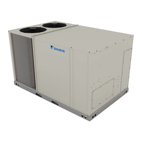
The AHKD series of electric heat kits is an accessory designed for
installationwiththeDaikinDAR0904orDAR1204AirhandlerONLY.
INSTALLATIONSWITHOTHERAIRHANDLERSISNOTPERMITTED.
For installation guidelines of the DAR0904 or DAR1204, refer to
the instructions which accompany the air handler, IOD-4010 (In-
stallation & Operating Instructions).
The AHKD provides supplemental electric heat for the DAR0904/
1204. The assembly is to be installed directly to the outlet of the
DAR0904/1204 and is not to be used as an independent duct
heater.
TheAHKD20 andAHKD30 heatkits havetwo stages. A twostage
room thermostat determines the staging by room temperature.
The heat kit’s control panel is “self contained” and is equipped
with all of the safety circuit/limits required per UL1995. The heat
kit employs a terminal block for installation of the high voltage
wires used by both the heat kit and the airhandler (single point
wiring).
C
HECKING
P
RODUCT
R
ECEIVED
Upon receiving the unit, inspect it for damage from shipment.
Claims for damage, either shipping or concealed, should be filed
immediatelywiththe shipping company.Donotinstall this acces-
sory if it is determined that the integrity or safety has been com-
promised by freight damage.
Check the unit model number, specifications, and electrical char-
acteristics to determine if they are correct. In the event an incor-
rect unit is shipped, it must be returned to the supplier and must
NOTbe installed. Themanufacturer assumes noresponsibility for
installation of incorrectly shipped units.
R
EPLACEMENT
P
ARTS
ORDERING PARTS
When reporting shortages or damages, or ordering repair parts,
give the complete unit model and serial numbers as stamped on
the product.
Replacementpartsforthisproductareavailablethroughyourcon-
tractor or local distributor. For the location of your nearest dis-
tributor, consult the white business pages, the yellow page sec-
tion of the local telephone book or contact:
CONSUMER AFFAIRS
DAIKIN NORTH AMERICA LLC
7401 SECURITY WAY
HOUSTON, TEXAS 77040
855-770-5678
I
MPORTANT
S
AFETY
I
NSTRUCTIONS
RECOGNIZE SAFETY SYMBOLS, WORDS, AND LABELS
Thefollowingsymbolsandlabelsareusedthroughoutthismanual
to indicate immediate or potential hazards. It is the owner’s re-
sponsibility to read and comply with all safety information and
instructions accompanying these symbols. Failure to heed safety
information increases the risk of property damage, product dam-
age, personal injury or death.
HIGH VOLTAGE!
D
ISCONNECT
ALL
POWER
BEFORE
SERVICING
.
M
ULTIPLE
POWER
SOURCES
MAY
BE
PRESENT
. F
AILURE
TO
DO
SO
MAY
CAUSE
PROPERTY
DAMAGE
,
PERSONAL
INJURY
OR
DEATH
.
WARNING
© 2013
5151 San Felipe, Suite 500, Houston, TX 77056
www.daikincomfort.com
P/N: IOD-7031 Date: December 2013
2
ONLY
INDIVIDUALS
MEETING
THE
REQUIREMENTS
OF
AN
“E
NTRY
L
EVEL
T
ECHNICIAN
”,
AT
A
MINIMUM
,
AS
SPECIFIED
BY
THE
A
IR
C
ONDITIONING
, H
EATING
AND
R
EFRIGERATION
I
NSTITUTE
(AHRI)
MAY
USE
THIS
INFORMATION
. A
TTEMPTING
TO
INSTALL
OR
REPAIR
THIS
UNIT
WITHOUT
SUCH
BACKGROUND
MAY
RESULT
IN
PRODUCT
DAMAGE
,
PERSONAL
INJURY
,
OR
DEATH
.
WARNING
T
O
AVOID
PROPERTY
DAMAGE
,
PERSONAL
INJURY
OR
DEATH
DUE
TO
ELECTRICAL
SHOCK
,
THIS
UNIT
MUST
HAVE
AN
,
ELECTRICAL
GROUND
. T
HE
ELECTRICAL
GROUND
CIRCUIT
MAY
CONSIST
OF
AN
APPROPRIATELY
SIZED
ELECTRICAL
WIRE
CONNECTING
THE
GROUND
LUG
IN
THE
UNIT
CONTROL
BOX
TO
THE
BUILDING
ELECTRICAL
SERVICE
PANEL
.
O
THER
METHODS
OF
GROUNDING
ARE
PERMITTED
IF
PERFORMED
IN
ACCORDANCE
WITH
THE
N
ATIONAL
E
LECTRIC
C
ODE
(NEC)/A
MERICAN
N
ATIONAL
S
TANDARDS
I
NSTITUTE
(ANSI)/N
ATIONAL
F
IRE
P
ROTECTION
A
SSOCIATION
(NFPA) 70
AND
LOCAL
/
STATE
CODES
. I
N
C
ANADA
,
ELECTRICAL
GROUNDING
IS
TO
BE
IN
ACCORDANCE
WITH
THE
C
ANADIAN
E
LECTRIC
C
ODE
(CSA) C22.1.
UNINTERRUPTED
UNBROKEN
WARNING
W
HEN
INSTALLING
OR
SERVICING
THIS
EQUIPMENT
,
SAFETY
CLOTHING
,
INCLUDING
HAND
AND
EYE
PROTECTION
,
IS
STRONGLY
RECOMMENDED
.
I
F
INSTALLING
IN
AN
AREA
THAT
HAS
SPECIAL
SAFETY
REQUIREMENTS
(
HARD
HATS
,
ETC
.), O
BSERVE
THESE
REQUIREMENTS
.
CAUTION
D
O
NOT
CONNECT
TO
OR
USE
ANY
DEVICE
THAT
IS
NOT
DESIGNED
CERTIFIED
BY
D
AIKIN
FOR
USE
WITH
THIS
UNIT
. S
ERIOUS
PROPERTY
DAMAGE
,
PERSONAL
INJURY
,
REDUCED
UNIT
PERFORMANCE
AND
/
OR
HAZARDOUS
CONDITIONS
MAY
RESULT
FROM
THE
USE
OF
SUCH
NON
-
APPROVED
DEVICES
.
WARNING
C
ODES
& R
EGULATIONS
This product is designed and manufactured to comply with na-
tional codes. Installation in accordance with such codes and/or
prevailing local codes/regulations is the responsibility of the in-
staller. The manufacturer assumes no responsibility for equip-
ment installed in violation of any codes or regulations.
P
RE
-I
NSTALLATION
I
NSTRUCTIONS
Carefully read all instructions for the installation prior to install-
ing product. Make sure each step or procedure is understood
and any special considerations are taken into account before
starting installation. Assemble all tools, hardware and supplies
needed to complete the installation. Some items may need to
bepurchasedlocally.Makesureeverythingneededtoinstallthe
product is on hand before starting.
M
ODEL
I
DENTIFICATION
Refertothismanualincombinationwiththeinstructionsprovided
with the air handler for the correct installation procedure.
The electrical characteristics of the air handler, the electric heat
kit and the building power supply must agree.
Usethe following tableand the product’sSeries and RatingPlate
to determine the heating kW and electrical characteristics.
Nominal
kW
AHKD15-3 15 208-230/3/60 1
AHKD15-4 15 460/3/60 1
AHKD20-3 20 208-230/3/60 2
AHKD20-4 20 460/3/60 2
AHKD30-3 30 208-230/3/60 2
AHKD30-4 30 460/3/60 2
AHKD Model
Number Electrical
Characteristics Stages
Table 1.
Forallsupplyvoltages,usethecorrectionfactorsinTables2&3,
multiplied by kW and (or) temperature rise to have corrected
results.
Supply Voltage 240 230 220 210 208
Correction Factor 1.0 0.92 0.84 0.77 0.75
KW Correction Factors (-3 models)
Table 2.
Supply Voltage 480 460 440 415 380
Correction Factor 1.0 0.92 0.84 0.75 0.63
KW Correction Factors (-4 models)
Table 3.
T
EMPERATURE
R
ISE
The heating mode temperature rise is dependent upon the sys-
tem airflow, the supply voltage, and the heat kit size (kW) se-
lected. Use Tables 4 & 5 to determine the temperature rise (oF):

3
DAR0904 Temperature Rise Table (DegreesF)
208 240 480
2800 14 19 19
2900 14 18 18
3000 13 18 18
3100 13 17 17
3200 12 17 17
2800 19 25 25
2900 18 24 24
3000 18 24 24
3100 17 23 23
3200 17 22 22
2800 28 38 38
2900 27 37 37
3000 27 35 35
3100 26 34 34
3200 25 33 33
Airhandler Heat Kit
KW CFM Supply Voltage
15
20
DAR0904
Temperature
Rise Table
(Degrees F)
30
Table 4.
DAR1204 Temperature Rise Table (DegreesF)
208 240 480
3800 10 14 14
3900 10 14 14
4000 10 13 13
4100 10 13 13
4200 9 13 13
3800 14 19 19
3900 14 18 18
4000 13 18 18
4100 13 17 17
4200 13 17 17
3800 21 28 28
3900 20 27 27
4000 20 27 27
4100 19 26 26
4200 19 25 25
CFM Supply Voltage
DAR1204
Temperature
Rise Table
(Degrees F)
15
20
30
Airhandler Heat Kit
KW
Table 5.
NOTE: Table 5 is calculated with both stages of electric heat en-
gaged (2 stage heat systems). For systems using staged electric
heat, divide the temperature rise from the table by 2 for 1st stage
operation.
E
LECTRICAL
S
UPPLY
W
IRE
AND
MOP
T
O
AVOID
THE
RISK
OF
FIRE
OR
EQUIPMENT
DAMAGE
,
USE
COPPER
CONDUCTORS
ONLY
.
WARNING
T
O
AVOID
PROPERTY
DAMAGE
,
PERSONAL
INJURY
OR
DEATH
DUE
TO
ELECTRICAL
SHOCK
,
THIS
UNIT
MUST
HAVE
AN
,
ELECTRICAL
GROUND
. T
HE
ELECTRICAL
GROUND
CIRCUIT
MAY
CONSIST
OF
AN
APPROPRIATELY
SIZED
ELECTRICAL
WIRE
CONNECTING
THE
GROUND
LUG
IN
THE
UNIT
CONTROL
BOX
TO
THE
BUILDING
ELECTRICAL
SERVICE
PANEL
.
O
THER
METHODS
OF
GROUNDING
ARE
PERMITTED
IF
PERFORMED
IN
ACCORDANCE
WITH
THE
N
ATIONAL
E
LECTRIC
C
ODE
(NEC)/A
MERICAN
N
ATIONAL
S
TANDARDS
I
NSTITUTE
(ANSI)/N
ATIONAL
F
IRE
P
ROTECTION
A
SSOCIATION
(NFPA) 70
AND
LOCAL
/
STATE
CODES
. I
N
C
ANADA
,
ELECTRICAL
GROUNDING
IS
TO
BE
IN
ACCORDANCE
WITH
THE
C
ANADIAN
E
LECTRIC
C
ODE
(CSA) C22.1.
UNINTERRUPTED
UNBROKEN
WARNING
INSPECTION OF THE BUILDING ELECTRICAL SERVICE.
T
HIS
UNIT
IS
DESIGNED
FOR
3-
PHASE
OPERATION
. DO NOT OPERATE
ON A SINGLE PHASE POWER SUPPLY. SEE THE “WARNING“
ABOVE.
M
EASURE
THE
POWER
SUPPLY
TO
THE
UNIT
. T
HE
SUPPLY
VOLTAGE
MUST
BE
IN
AGREEMENT
WITH
THE
UNIT
NAMEPLATE
POWER
REQUIREMENTS
AND
WITHIN
THE
RANGE
SHOWN
IN
T
ABLE
6.
WARNING
Building Electrical Service Inspection
This unit is designed for 3-phase operation. DO NOT OPERATE
ON A SINGLE PHASE POWER SUPPLY. SEE THE PRECEDING
WARNING. Measure the power supply to the unit. The supply
voltage MUST be in agreement with the unit nameplate power
requirements and within the range shown in Table 6.
Minimum Supply Maximum Supply
Voltage Voltage
208 –230 187 253
460 414 506
Nominal
Table 6.
Voltage Balance The supply voltage shall be unbalance (phase to
phase)within2%. To calculate the percentage of voltage unbalance
use the following formula:
Percentage Max Voltage Deviation From Avg Volt-
age Unbalance = 100 x Average Voltage
Example . L1 – L2 = 220 V
L2 – L3 = 216 V
L1 – L3 = 213 V
Avg. Voltage = (220+216+213) / 3
= 649 / 3
= 216
Max. Deviation from Avg. = 220 – 216 = 4
% VoltageUnbalance = 100 x (4 / 216)
= 400 / 216
= 1.8%

4
Determine Wire Size The selection of the appropriate supply
wire size is important to the operation of the equipment.
When selecting the wire size, the following are important
elements of the decision:
· Thewiresize is adequatelysizedto carry theMinimumCir-
cuit Ampacity (MCA). Refer to the NEC (USA) or CSA
(Canada) for wire sizing. The unit MCA for the air handler
andtheoptionalelectricheatkitcanbefoundontheequip-
ment S&R plate and the following table.
AIRHANDLER VOLTAGE HEATKIT MCA
None 6.5
AHKD15-3 49.8
AHKD20-3 64.2
AHKD30-3 93.1
None 3.3
AHKD15-4 24.9
AHKD20-4 32.1
AHKD30-4 46.6
None 9.8
AHKD15-3 53.1
AHKD20-3 67.5
AHKD30-3 96.4
None 4.9
AHKD15-4 26.5
AHKD20-4 33.7
AHKD30-4 48.2
DAR0904
208-230
460
DAR1204
208-230
460
Table 7.
· The wire size is appropriately sized to allow for no more
thana2%voltagedropfromthebuildingbreaker/fusepanel
to the unit.
· Refer to the latest edition of the National Electric Code or
in Canada the Canadian Electric Code when determining
the correct wire size.
Table 8 shows the current carrying capabilities for copper con-
ductors rated at 75oC with a 2% voltage drop. Use Table 8 to de-
termine the voltage drop per foot of various conductors.
Wire
Size
(AWG)1015202530354045
14 75 50 37 NR NR NR NR NR
12118795947NRNRNRNR
10 188 125 95 75 63 54 NR NR
8 301 201 150 120 100 86 75 68
6 471 314 235 188 157 134 118 110
BasedonNEC1996
Max. Allowable Length in Feet to Limit Voltage
Drop to 2%
Min. Circuit Ampacity(MCA)
Table 8.
M
AXIMUM
O
VERCORRECT
P
ROTECTION
(MOP)
Every installation must include an NEC (USA) or CEC (Canada) ap-
proved overcorrect protection device. Also, check with local or
state codes for any special regional requirements.
ProtectioncanbeintheformoffusingorHACRstylecircuitbreak-
ers. TheSeriesandRatingPlatecan be used asa guidefor select-
ing the MAXIMUM overcurrent device or reference the following
table.
NOTE: Fuses or circuit breakers are to be sized larger than the
equipment MCA but not to exceed the MOP.
AIRHANDLER HEATKIT MOP
None 15
AHKD15-3 50
AHKD20-3 70
AHKD30-3 100
None 15
AHKD15-4 25
AHKD20-4 35
AHKD30-4 50
None 15
AHKD15-3 60
AHKD20-3 70
AHKD30-3 100
None 15
AHKD15-4 30
AHKD20-4 35
AHKD30-4 50
DAR0904
DAR1204
Table 9.
A
TTACHING
THE
H
EAT
K
IT
1. Securethehighvoltageandlowvoltageconduitstotheheat
kitelectricalpanelusingthesuppliedplastic bushing nuts as
shown in Figure 1.
LOW VOLTAGE
WIRES
HIGH VOLTAGE
WIRES
Figure 1.

5
2. Theheatkitattachesdirectlytothetoppanel(whenviewed
intheupflow position)oftheair handler. Do notscrewthe
heatkitintothe ductflanges. Positiontheheatkitontothe
air handler at the air discharge end with the control box
orientated toward the airhandler front. See Figure 2.
Figure 2.
3. Route the two electrical conduits (attached in step 1.)
through the panel on the airhandler. Secure the conduits
to the air handler panel with the supplied plastic bushing
nuts.
4. Using the supplied ½” long #10 screws, attach the heat kit
to the air handler outlet panel. Note: Open the heat kit
electrical panel door to obtain access to the three screws
on that side.
5. Follow the “Electrical Connections” section of this manual
for wiring details.
E
LECTRICAL
C
ONNECTIONS
T
O
AVOID
THE
RISK
OF
FIRE
OR
EQUIPMENT
DAMAGE
,
USE
COPPER
CONDUCTORS
ONLY
.
WARNING
Supply Voltage
A single point supply voltage termination is provided in the heat
kit control box. The wire is to be sized in accordance with the
Electrical Wire and MOP section of this manual.
The supply wire is to be routed through conduit from the service
disconnect box to the heater kit. The heat kit is equipped with a
knockout suitable for 1/2” or 3/4” conduit., dependent on the
kW. The supply voltage is to be installed on the terminal block
located in the heater kit control box.
The heater kit is factory equipped with the supply and low volt-
age wires for the air handler. The low voltage connection from
the heater kit is provided through a multi-pin plug which con-
nects to a mating plug in the air handler. The high voltage con-
nectionsaretobemadeattheairhandlercontactor. Thesewires
aretoberoutedthroughthepipenipplessuppliedwiththeheater
kit as shown in the following illustration.
LOW VOLTAGE
WIRES
HIGH VOLTAGE
WIRES
Figure 3.
Route the air handler supply voltage and ground conductors
thoughthe½”conduitthatconnectstheheatkittotheairhandler.
Attach the supply voltage wires to the airhandler contactor and
the equipment ground to the airhandler ground lug. To assist
with possible troubleshooting, follow the wire color conventions
indicated on the wiring diagram.
Figure 4.
Low Voltage Connections
Thelowvoltageconnectionfromthe air handlerto theheatkitis
providedthrough a multi-pinplugthat connects toamating plug
intheairhandler. Routetheheatkit lowvoltageharness through
the 1 ½” conduit to the airhandler control box and plug into the
airhandlerlowvoltageharness. Note: Lowvoltagefromtheroom
thermostat is terminated in the airhandler control box. Wiring
options for the thermostat wiring are shown in the air handler
installation manual.

6
Figure 5.
Single Stage Heat - Single Stage Cooling where
R - Red
W - White
G - Green
BL - Blue
Note: Brown wire is not used and is to be taped.
Figure 6.
Two-Stage Heat - Single Stage Cooling where
R - Red
W - White
BR - Brown
G - Green
BL - Blue

7
L3L1 L2
Legend
FR – Fan Relay
FU – Fuse
TB – Terminal Block
HC – Heater Contactor
HTR – Heater Element
PLS – Primary Limit Switch
SLS – Secondary Limit Switch
L3L1 L2
Wiring is subject to change, always refer to the wiring diagram on the unit for the most up-to-date wiring.
WARNING
WIRING DIAGRAM

8
L3L1 L2
Wiring is subject to change, always refer to the wiring diagram on the unit for the most up-to-date wiring.
WARNING
WIRING DIAGRAM
L3L2L1
Legend
FR – Fan Relay
FU – Fuse
TB – Terminal Block
HC – Heater Contactor
HTR – Heater Element
PLS – Primary Limit Switch
SLS – Secondary Limit Switch
This manual suits for next models
1
Table of contents
Other Daikin Heater manuals

Daikin
Daikin KEH067A41E(A) User manual

Daikin
Daikin DRC User manual

Daikin
Daikin REYQ8-48PY1B User manual

Daikin
Daikin Altherma 3 GEO Product information sheet

Daikin
Daikin KEH041A41 User manual

Daikin
Daikin KEH094A41E User manual

Daikin
Daikin KEH041A43 User manual

Daikin
Daikin Altherma 3 H HT F User manual

Daikin
Daikin KEH041A42 User manual

Daikin
Daikin EHXD User manual