Graco GH 24X011 Parts list manual

334914A
EN
Instructions - Parts
GH
™
Power Pack
Use to power XP-h
™
Hydraulic Plural-Component Sprayers. For professional use only.
Not approved for use in explosive atmospheres or hazardous locations.
Part No. 24X011
Maximum Working Pressure 1800 psi (12.4 MPa, 124 bar)
Related Manuals
Important Safety Instructions
Read all warnings and instructions in this
manual and in related manuals. Save these
instructions.
Manual No. Description
3A0420 XP
™
and XP-h Proportioners
WLD

2334194A
Contents
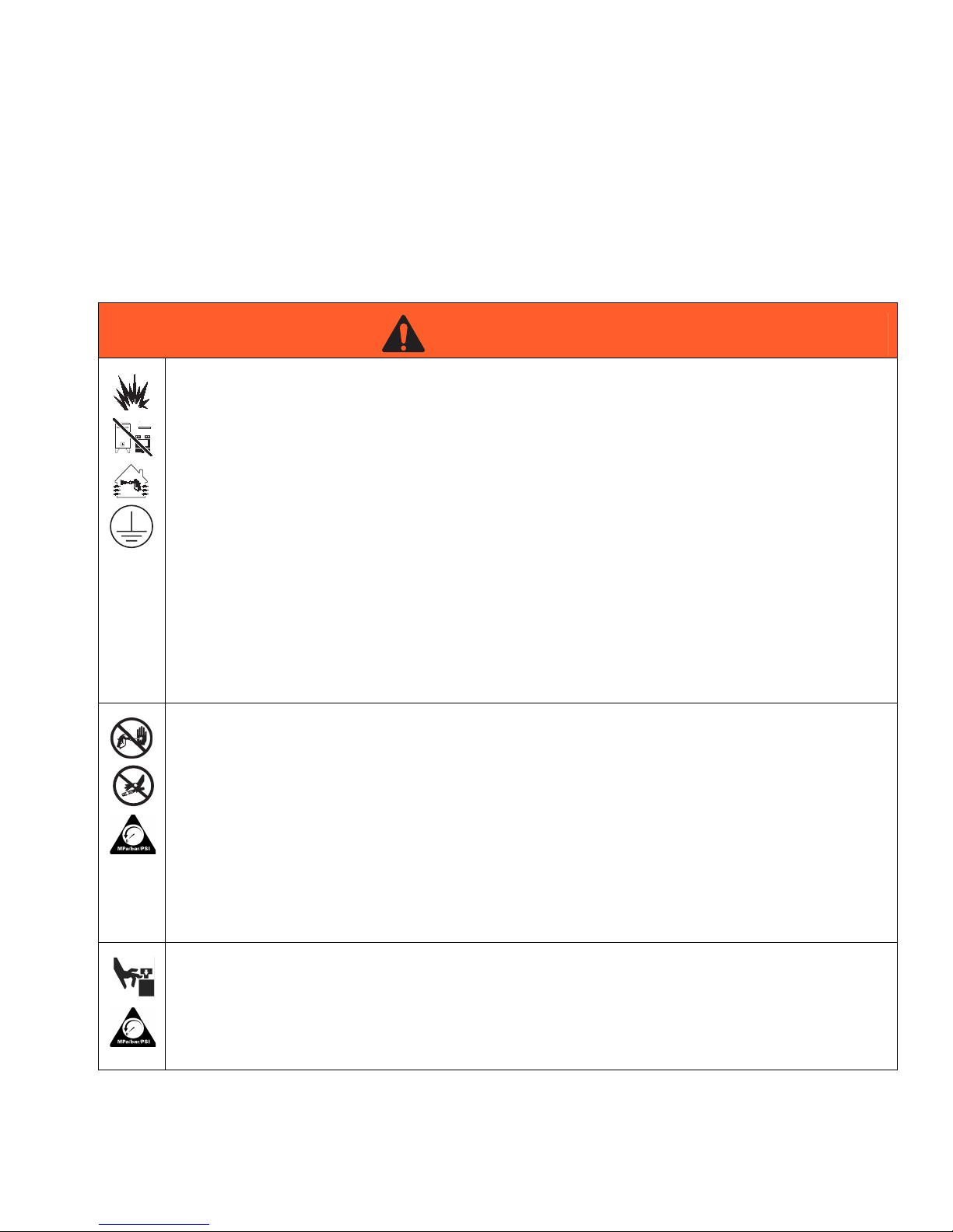
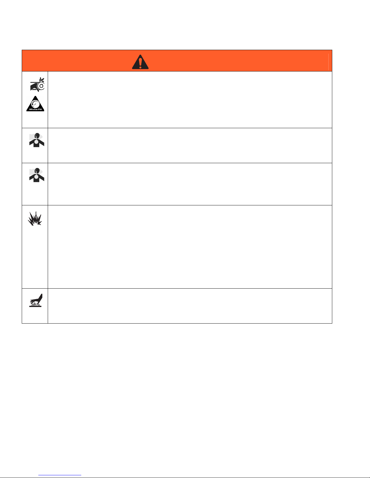
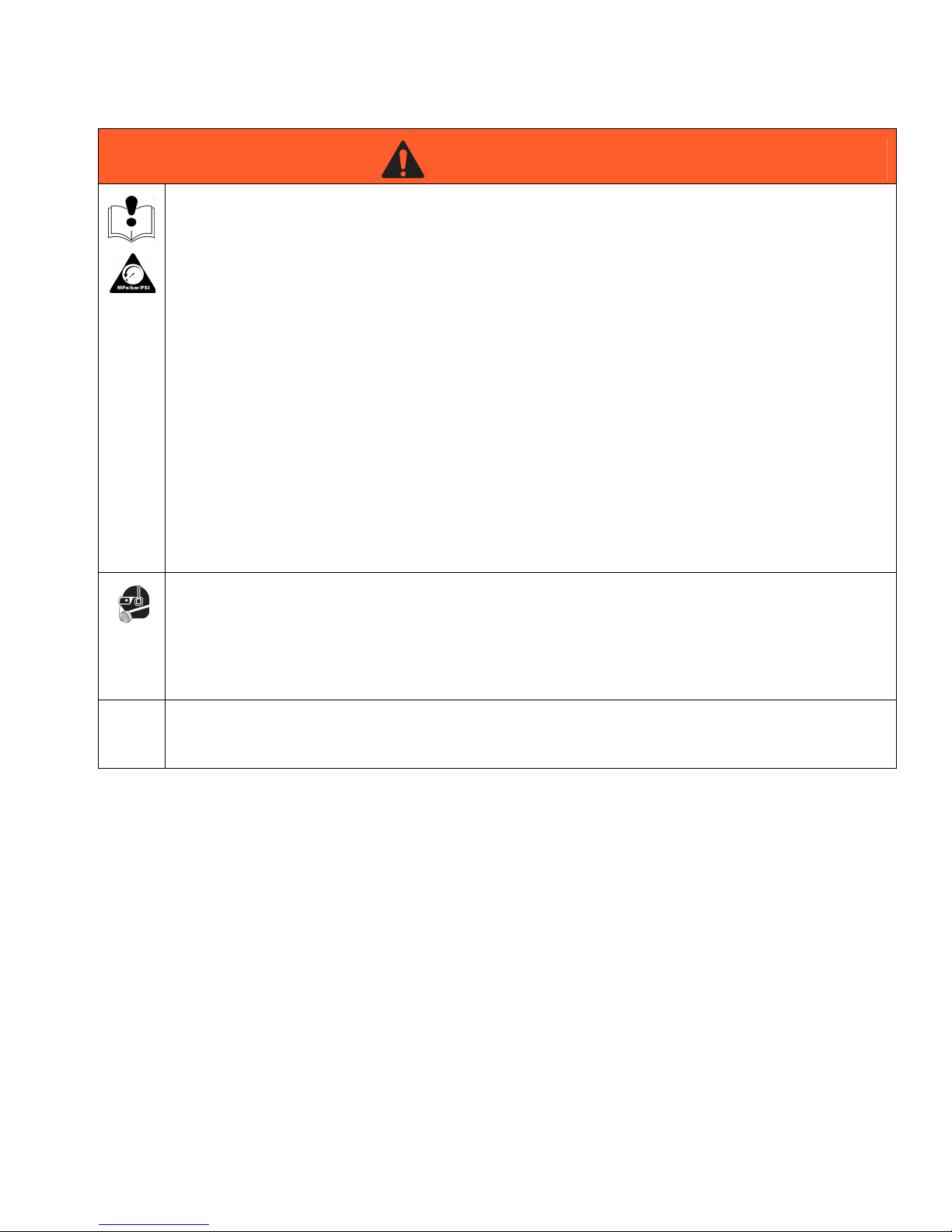
Warnings . . . . . . . . . . . . . . . . . . . . . . . . . . . . . . . . . 3
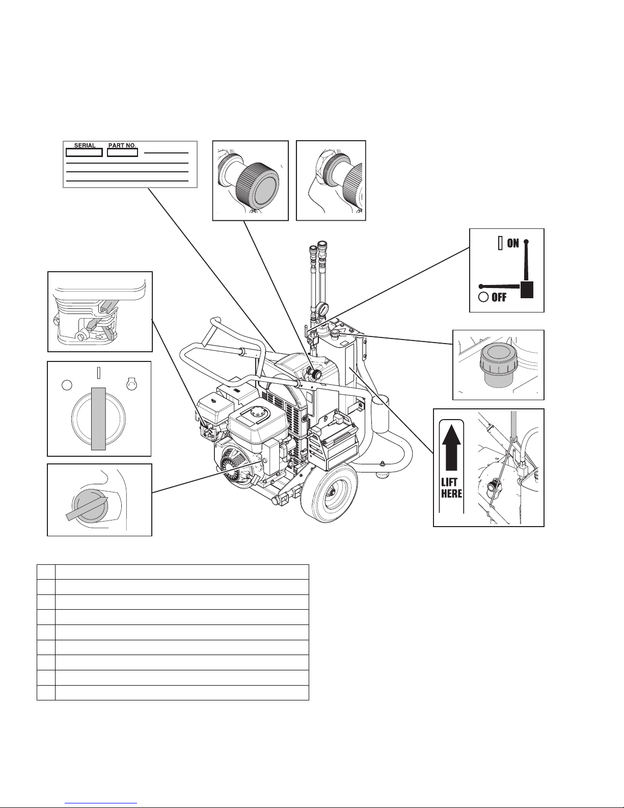
Component Identification . . . . . . . . . . . . . . . . . . . . 6
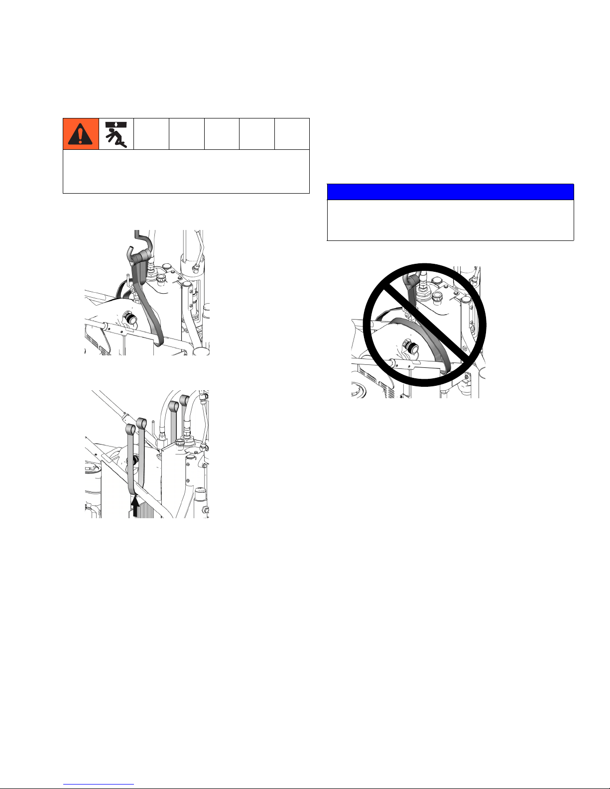
Lift Instructions . . . . . . . . . . . . . . . . . . . . . . . . . . . . 7
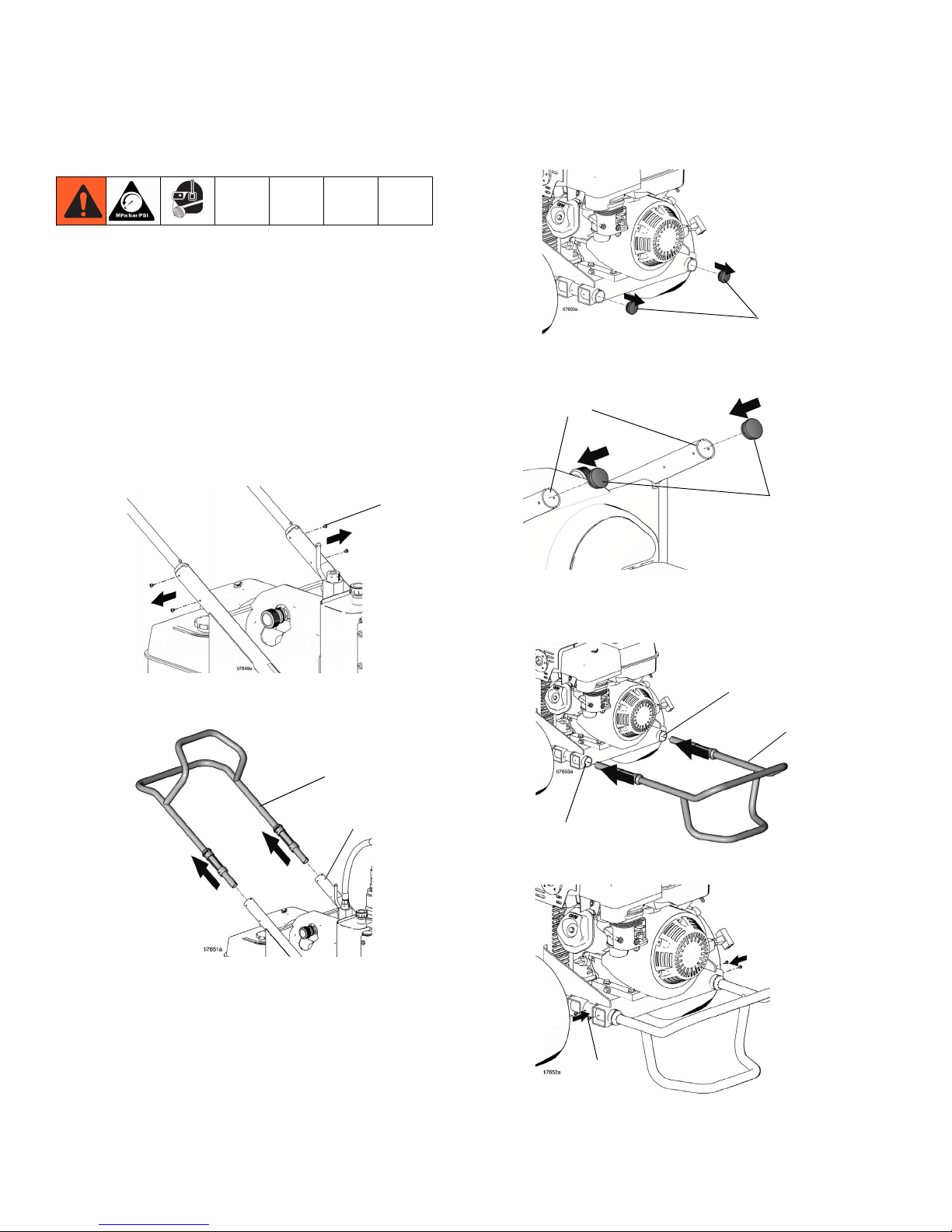
Removing Handle . . . . . . . . . . . . . . . . . . . . . . . . . . 8
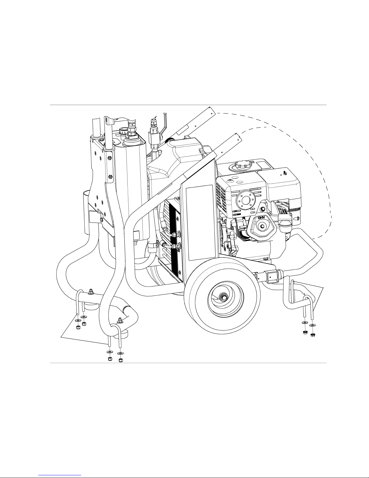
Fixed Mounting (optional) . . . . . . . . . . . . . . . . . . 8
Repositioning Handle . . . . . . . . . . . . . . . . . . . . . 8
Securing Unit to Vehicle Bed . . . . . . . . . . . . . . . . . 9
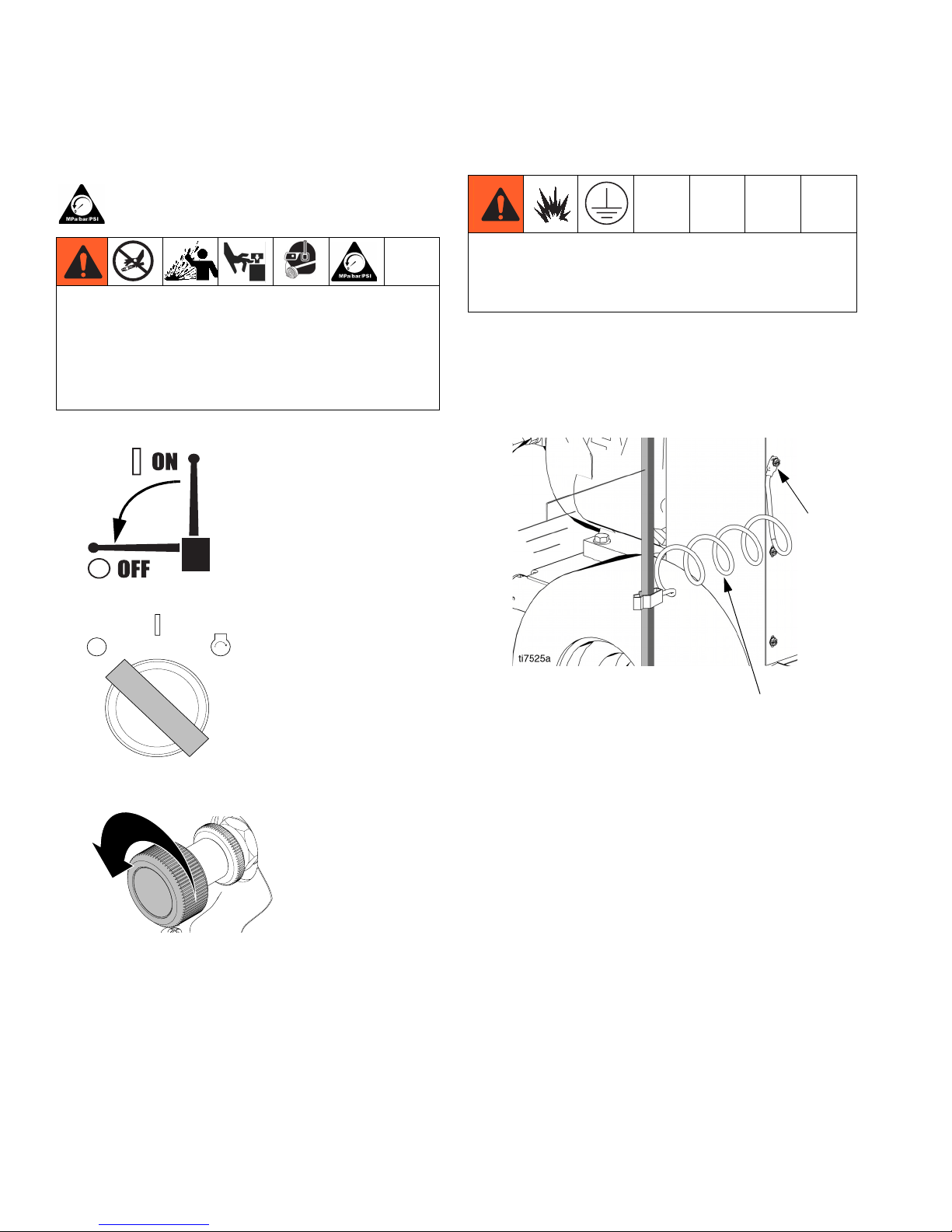
Pressure Relief Procedure . . . . . . . . . . . . . . . . . . 10
Grounding . . . . . . . . . . . . . . . . . . . . . . . . . . . . . . . 10
Setup . . . . . . . . . . . . . . . . . . . . . . . . . . . . . . . . . . . . 11
Startup . . . . . . . . . . . . . . . . . . . . . . . . . . . . . . . . . . 12
Spraying . . . . . . . . . . . . . . . . . . . . . . . . . . . . . . . . . 13
Maintenance . . . . . . . . . . . . . . . . . . . . . . . . . . . . . . 14
Troubleshooting . . . . . . . . . . . . . . . . . . . . . . . . . . 15
Compensator Seal Replacement . . . . . . . . . . . . . 16
Removal . . . . . . . . . . . . . . . . . . . . . . . . . . . . . . 16
Hydraulic Pump Replacement . . . . . . . . . . . . . . . 17
Changing Hydraulic Oil . . . . . . . . . . . . . . . . . . . 17
Removal . . . . . . . . . . . . . . . . . . . . . . . . . . . . . . 17
Installation . . . . . . . . . . . . . . . . . . . . . . . . . . . . . 19
Belt Removal and Installation . . . . . . . . . . . . . . . 21
Replacing Oil Reservoir . . . . . . . . . . . . . . . . . . . . 22
Removal . . . . . . . . . . . . . . . . . . . . . . . . . . . . . . 22
Installation . . . . . . . . . . . . . . . . . . . . . . . . . . . . . 23
Changing Hydraulic Oil Filter . . . . . . . . . . . . . . . . 25
Removal . . . . . . . . . . . . . . . . . . . . . . . . . . . . . . 25
Installation . . . . . . . . . . . . . . . . . . . . . . . . . . . . . 25
Cooler Replacement . . . . . . . . . . . . . . . . . . . . . . . 26
Removal . . . . . . . . . . . . . . . . . . . . . . . . . . . . . . 26
Installation . . . . . . . . . . . . . . . . . . . . . . . . . . . . . 27
Engine Replacement . . . . . . . . . . . . . . . . . . . . . . . 28
Removal . . . . . . . . . . . . . . . . . . . . . . . . . . . . . . 28
Installation . . . . . . . . . . . . . . . . . . . . . . . . . . . . . 28
Engine Replacement . . . . . . . . . . . . . . . . . . . . . 29
Battery Replacement . . . . . . . . . . . . . . . . . . . . . . . 30
Removal . . . . . . . . . . . . . . . . . . . . . . . . . . . . . . 30
Installation . . . . . . . . . . . . . . . . . . . . . . . . . . . . . 30
Frame . . . . . . . . . . . . . . . . . . . . . . . . . . . . . . . . . . . 32
Frame Parts List . . . . . . . . . . . . . . . . . . . . . . . . 33
Frame (continued) . . . . . . . . . . . . . . . . . . . . . . . . . 34
Frame (Continued) Parts List . . . . . . . . . . . . . . 35
Hydraulic Pump and Reservoir . . . . . . . . . . . . . . . 36
Hydraulic Pump and Reservoir Parts List . . . . . 37
Battery . . . . . . . . . . . . . . . . . . . . . . . . . . . . . . . . . . . 38
Parts List . . . . . . . . . . . . . . . . . . . . . . . . . . . . . . 38
Technical Data . . . . . . . . . . . . . . . . . . . . . . . . . . . . 39
Graco Standard Warranty . . . . . . . . . . . . . . . . . . . 40

Warnings
334194A 3
Warnings
The following warnings are for the setup, use, grounding, maintenance, and repair of this equipment. The exclama-
tion point symbol alerts you to a general warning and the hazard symbols refer to procedure-specific risks. When
these symbols appear in the body of this manual or on warning labels, refer back to these Warnings. Product-specific
hazard symbols and warnings not covered in this section may appear throughout the body of this manual where
applicable.
WARNINGWARNINGWARNING
WARNING
FIRE AND EXPLOSION HAZARD
Flammable fumes, such as solvent and paint fumes, in work area can ignite or explode. To help prevent
fire and explosion:
• Use equipment only in well ventilated area.
• Do not fill fuel tank while engine is running or hot; shut off engine and let it cool. Fuel is flammable
and can ignite or explode if spilled on hot surface.
• Eliminate all ignition sources; such as pilot lights, cigarettes, portable electric lamps, and plastic drop
cloths (potential static arc).
• Keep work area free of debris, including solvent, rags and gasoline.
• Do not plug or unplug power cords, or turn power or light switches on or off when flammable fumes
are present.
• Ground all equipment in the work area. See Grounding instructions.
• Use only grounded hoses.
• Hold gun firmly to side of grounded pail when triggering into pail. Do not use pail liners unless they
are antistatic or conductive.
•Stop operation immediately if static sparking occurs or you feel a shock.Do not use equipment
until you identify and correct the problem.
• Keep a working fire extinguisher in the work area.
SKIN INJECTION HAZARD
High-pressure fluid from gun, hose leaks, or ruptured components will pierce skin. This may look like just
a cut, but it is a serious injury that can result in amputation. Get immediate surgical treatment.
• Do not spray without tip guard and trigger guard installed.
• Engage trigger lock when not spraying.
• Do not point gun at anyone or at any part of the body.
• Do not put your hand over the spray tip.
• Do not stop or deflect leaks with your hand, body, glove, or rag.
•FollowthePressure Relief Procedure when you stop spraying and before cleaning, checking, or
servicing equipment.
• Tighten all fluid connections before operating the equipment.
• Check hoses and couplings daily. Replace worn or damaged parts immediately.
MOVING PARTS HAZARD
Moving parts can pinch, cut or amputate fingers and other body parts.
• Keep clear of moving parts.
• Do not operate equipment with protective guards or covers removed.
• Pressurized equipment can start without warning. Before checking, moving, or servicing equipment,
follow the Pressure Relief Procedure and disconnect all power sources.

Warnings
4334194A
ENTANGLEMENT HAZARD
Rotating parts can cause serious injury.
• Keep clear of moving parts.
• Do not operate equipment with protective guards or covers removed.
• Do not wear loose clothing, jewelry or long hair while operating equipment.
• Equipment can start without warning. Before checking, moving, or servicing equipment, follow the
Pressure Relief Procedure and disconnect all power sources.
CARBON MONOXIDE HAZARD
Exhaust contains poisonous carbon monoxide, which is colorless and odorless. Breathing carbon mon-
oxide can cause death.
• Do not operate in an enclosed area.
TOXIC FLUID OR FUMES HAZARD
Toxic fluids or fumes can cause serious injury or death if splashed in the eyes or on skin, inhaled, or
swallowed.
• Read MSDSs to know the specific hazards of the fluids you are using.
• Store hazardous fluid in approved containers, and dispose of it according to applicable guidelines.
BATTERY SAFETY
The battery may leak, explode, cause burns, or cause an explosion if mishandled.
• Only use the battery type specified for use with the equipment.
• Battery maintenance must only be performed or supervised by personnel knowledgeable of
batteries and the required precautions. Keep unauthorized personnel away from battery.
• Do not dispose of battery in fire. The battery is capable of exploding.
• Follow local ordinances and/or regulations for disposal.
• Do not open or mutilate the battery. Released electrolyte has been known to be harmful to the skin
and eyes and to be toxic.
• Remove watches, rings, or other metal objects.
• Only use tools with insulated handles. Do not lay tools or metal parts on top of battery.
BURN HAZARD
Equipment surfaces and fluids that are heated can become very hot during operation. To avoid severe
burns:
• Do not touch hot fluid or equipment.
WARNINGWARNINGWARNING
WARNING

Warnings
334194A 5
EQUIPMENT MISUSE HAZARD
Misuse can cause death or serious injury.
• Do not operate the unit when fatigued or under the influence of drugs or alcohol.
• Do not exceed the maximum working pressure or temperature rating of the lowest rated system
component. See Technical Data in all equipment manuals.
• Use fluids and solvents that are compatible with equipment wetted parts. See Technical Data in all
equipment manuals. Read fluid and solvent manufacturer’s warnings. For complete information
about your material, request MSDS from distributor or retailer.
• Do not leave the work area while equipment is energized or under pressure.
• Turn off all equipment and follow the Pressure Relief Procedure when equipment is not in use.
• Check equipment daily. Repair or replace worn or damaged parts immediately with genuine manu-
facturer’s replacement parts only.
• Do not alter or modify equipment. Alterations or modifications may void agency approvals and create
safety hazards.
• Make sure all equipment is rated and approved for the environment in which you are using it.
• Use equipment only for its intended purpose. Call your distributor for information.
• Route hoses and cables away from traffic areas, sharp edges, moving parts, and hot surfaces.
• Do not kink or over bend hoses or use hoses to pull equipment.
• Keep children and animals away from work area.
• Comply with all applicable safety regulations.
PERSONAL PROTECTIVE EQUIPMENT
Wear appropriate protective equipment when in the work area to help prevent serious injury, including
eye injury, hearing loss, inhalation of toxic fumes, and burns. Protective equipment includes but is not
limited to:
• Protective eyewear, and hearing protection.
• Respirators, protective clothing, and gloves as recommended by the fluid and solvent manufacturer.
CALIFORNIA PROPOSITION 65
The engine exhaust from this product contains a chemical known to the State of California to cause can-
cer, birth defects or other reproductive harm.
WARNINGWARNINGWARNING
WARNING

Component Identification
6334194A
Component Identification
1 Engine Controls
2 Engine ON/OFF Switch (Electric-Start Units)
3 Ignition
4 Lift Location
6 Pressure Control
7 Lock Ring
8 Serial Number ID Label
9 Hydraulic Pump Valve
10 Hydraulic Oil Fill
ON
OFF
WLE
1
2
4
10
9
867
OFF
ON
START
3

Lift Instructions
334194A 7
Lift Instructions
1. When lifting the power pack, balance weight evenly
across two straps/chains as shown.
2. Wrap each strap/chain securely around frame
where indicated on frame label as shown.
3. Be sure straps/chains used for lifting are rated to
support weight of the power pack: 390 lbs (177 kg).
NOTE: Lift power pack and sprayer components sepa-
rately. Disconnect fluid hoses.
To avoid injury, always use designated Lift Locations
when lifting the unit. Always use approved equipment
for securing the unit to transporting equipment.
ti7840a
ti7855a
NOTICE
Do not lift unit with only one strap secured across
pump. This could put stress on frame and damage
pump.
ti7838a

Removing Handle
8334194A
Removing Handle
Fixed Mounting (optional)
To prevent damaging the unit when transporting it in a
truck or on a trailer, Graco recommends fixed mounting
to the vehicle.
Repositioning Handle
Before you can secure the unit to a truck or trailer bed,
you must reposition the handle.
1. Remove the 4 handle sleeve screws (143).
2. Remove handle assembly (25) by pulling it out of
upper frame tubes (1).
3. Remove frame tube plugs (120) located behind the
wheels.
4. Insert plugs (120) in upper frame handle tubes (a).
5. Insert handle assembly (25) into lower frame tubes
(b). The hose bracket should face down. Adjust to
appropriate in/out location.
6. Install sleeve screws (143) in lower frame tubes.
143
25
1
120
120
(a)
ti7744a
25
25
(b)
(b)
143

Securing Unit to Vehicle Bed
334194A 9
Securing Unit to Vehicle Bed
For fixed mounting, fasten U-bolts over sprayer frame
as indicated in the following illustration.
1. Reposition handle, steps 1-5, page 8.
2. Place U-bolts over sprayer frame and through holes
in vehicle bed. Place a washer and nut over bolt
end. Using a wrench, tighten nut securely.
U-bolts
U-bolts
Reposition Handle
ti20932a

Pressure Relief Procedure
10 334194A
Pressure Relief Procedure
Follow the Pressure Relief Procedure whenever
you see this symbol.
1. Set pump valve OFF.
2. Turn engine OFF.
3. Loosen Lock Ring. Turn pressure control to lowest
setting.
4. Trigger gun into pail to relieve pressure.
5. See XP-h manual 3A0420 for the Pressure Relief
Procedure of the XP-h proportioner.
Grounding
Use ground wire and clamp (supplied). Loosen ground-
ing lug locknut (W) and washer (X). Insert ground wire
end (Y) into lug (Z) slot and tighten locknut securely.
Connect ground clamp to a true earth ground.
This equipment stays pressurized until pressure is
manually relieved. To help prevent serious injury
from pressurized fluid, such as skin injection,
splashing fluid and moving parts, follow the Pressure
Relief Procedure when you stop spraying and before
cleaning, checking, or servicing the equipment.
ti7108a
ti20967a
OFF
ON
START
ti7111b
The equipment must be grounded to reduce the risk of
static sparking. Static sparking can cause fumes to
ignite or explode. Grounding provides an escape wire
for the electric current.
Y
W, X, Z

Setup
334194A 11
Setup
1. Follow Setup instructions in the XP-h Proportioner
manual.
2. Check engine oil level. Add SAE 10W-30 (summer)
or 5W-20 (winter), if necessary.
3. Fill engine fuel tank.
4. Remove the hydraulic oil fill cap (27) and check the
hydraulic reservoir oil level. Add only Graco Hydrau-
lic Oil, ISO 46 169236 (5 gallon/18.9 liter) or 207428
(1 gallon/3.8 liter). Hydraulic reservoir capacity is
approximately 4.0 gallons (15.14 liters).
5. Verify all hose/fitting connections from the power
pack and XP-h Proportioner are tight.
(cold)
ti5241a
ti5242a
Attach XP-h Proportioner grounding clamp to earth
ground to reduce the risk of static sparking. See XP
Proportioner manual for instructions.
Safe Range (cold)
ti5243a
27
WLE

Startup
12 334194A
Startup
1. Loosen lock nut and turn pressure control counter-
clockwise to lowest pressure.
2. Set pump valve OFF.
3. Start engine.
a. Move fuel valve to open.
b. Move choke to closed.
c. Set throttle to fast.
d. Rotate key to start.
e. After engine starts, move choke to open.
f. Set throttle to desired setting.
Hydraulic system and engine may become very hot
during operation and could burn skin if touched.
Flammable materials spilled on hot, bare motor could
cause fire or explosion. Have belt guard in place
during operation to reduce risk of entanglement or
loss of fingers.
ti7111b
ti7108a
ti5248a
ti5249a
ti5250a
ti20966a
OFF
ON
START
ti5264a
ti5251a

Spraying
334194A 13
Spraying
1. Set pump valve ON.
2. Increase pressure enough to start hydraulic motor
stroking and allow fluid to circulate for 15 seconds;
turn pressure down.
3. Turn spray gun trigger safety OFF.
4. Adjust pressure to desired setting. Begin spraying.
5. Rotate Lock Ring clockwise to set pressure.
ti7108a
ti7110c
ti21143a
ti7110c ti21062a
ti20968a

Maintenance
14 334194A
Maintenance
For detailed engine maintenance and specifications,
refer to separate Honda Engines Owner’s Manual,
supplied.
Spark Plug:
• Use BPR6ES (NGK) or W20EPR-U
(NIPPONDENSO) plug, only.
• Gap plug to 0.028 to 0.031 in. (0.7 to 0.8 mm).
• Use spark plug wrench when installing and
removing plug.
Frequency Procedure
Daily Check engine oil level and fill as necessary.
Daily Check hydraulic oil level and fill as necessary.
Daily Check hose for wear and damage.
Daily Check gun safety for proper operation.
Daily Check pressure drain valve for proper operation.
Daily Check and fill gas tank.
After first 20 hours
of operation
Drain engine oil and refill with clean oil. Reference Honda Engines Owner’s Manual for
correct oil viscosity.
Weekly
Remove engine air filter cover and clean element. Replace element, if necessary. If operating
in an unusually dusty environment; check filter daily and replace, if necessary.
Replacement elements can be purchased from your local Honda dealer.
Weekly/Daily Remove and debris or media from hydraulic rod.
After each 100
hours of operation Change engine oil. Reference Honda Engines Owner’s Manual for correct oil viscosity.
Semi-annually Check belt wear; replace if necessary.
Yearly or 2000
hours
Replace hydraulic oil and filter element with Graco ISO 46 Hydraulic Oil 169236;
5 gallon/20 liter or 207428; 1 gallon/3.8 liter) and filter element 287871.

Troubleshooting
334194A 15
Troubleshooting
PROBLEM CAUSE SOLUTION
Gas engine pulls hard (will not start). Hydraulic pressure is too high. Turn hydraulic pressure knob coun-
terclockwise to lowest setting.
Gas engine does not start. Switch OFF, low oil, no gasoline or
dead battery.
Consult engine manual, supplied.
Change battery if necessary.
Gas engine doesn't work properly. Faulty engine. Consult engine manual, supplied.
Gas engine operates, but displace-
ment pump doesn't operate.
Pump valve is OFF. Set pump valve ON.
Pressure setting too low. Increase pressure.
Tip or tip filter (if used) is clogged. Remove tip and/or filter and clean.
Hydraulic fluid too low. Shut off sprayer. Add fluid*.
Belt worn, broken or off. Replace belt.
Hydraulic pump worn or damaged. Bring sprayer to Graco distributor for
repair.
Hydraulic motor not shifting. Set pump valve OFF. Turn pressure
down. Turn engine OFF. Pry rod up
or down until hydraulic motor shifts.
Excessive leakage around hydraulic
motor piston rod wiper.
Piston rod seal worn or damaged. Replace these parts.
Fluid delivery is low. Pressure setting too low. Increase pressure.
Displacement pump outlet filter (if
used) is dirty or clogged.
Clean filter.
Intake line to pump inlet is not tight. Tighten.
Hydraulic motor is worn or damaged. Bring sprayer to Graco distributor for
repair.
Large pressure drop in fluid hose. Use larger diameter or shorter hose.
The sprayer overheats. Paint buildup on hydraulic compo-
nents.
Clean hydraulic components.
Oil level is low. Fill with oil.
Excessive hydraulic pump noise. Low hydraulic fluid level. Turn sprayer OFF. Add fluid*.
*Check hydraulic fluid level often. Do not allow it to become too low. Use only Graco approved hydraulic fluid, page 25.

Compensator Seal Replacement
16 334194A
Compensator Seal
Replacement
Removal
1. Perform Pressure Relief Procedure, page 10.
2. Remove screw (197) and pump handle cover (196).
Remove four cover bolts (79) and cover (140).
NOTE: It is not necessary to remove the hydraulic
lines before removing the cover. The cover is
designed to provide ample room for the cover to fit
over the hose.
3. Remove compensator screws and separate com-
pensator and adapter block.
4. Install new gaskets and torque screws.
5. Install cover (140) with four screws (79). Torque to
25-30 in-lb (2.8 - 3.4 N
z
m). Install pump handle
cover (196) with screw (197).
Allow hydraulic system to cool before beginning the
service procedure to prevent injury.
ti7805c
140
79
196
197
Torque 50 in-lb
4 plcs
Adapter
Block
O-Ring
Gasket
O-Ring
Lubricate before installation
ti17601a
Gasket
Note Gasket Orientation
Compensator
Assembly
Torque 50 in-lb
4 plcs
1
4
3
2
Torque sequence: 1-2-3-4-1
All cap screws must be tightened
When compensator assembled to
Gasket Adaptor Block. Do not
pre-tighten cap screws.
ti7811c
140
197 196
79

Hydraulic Pump Replacement
334194A 17
Hydraulic Pump Replacement
Changing Hydraulic Oil
Draining Oil
a. Place drain pan under oil reservoir and drain
plug.
b. Unscrew reservoir (64) drain plug and drain oil
from reservoir.
Refilling Oil
a. Replace drain plug.
b. Fill tank with Graco Hydraulic Oil, ISO 46. Res-
ervoir holds approximately 4 gallons (15.14
liters).
Removal
1. Perform Pressure Relief Procedure, page 10.
2. Drain oil, Changing Hydraulic Oil procedure,
page 17.
3. Remove screw (197) and pump handle cover (196).
Remove four cover bolts (79) and cover (140). (It is
not necessary to remove the hydraulic lines before
removing cover. The cover is designed to provide
ample room for the cover to fit over the hose.)
4. Unscrew suction line connections to hydraulic
pump. Place a container under hoses to catch any
dripping oil.
NOTICE
To prevent damage to the hydraulic pump,
only use hydraulic fluid.
Allow hydraulic system to cool before beginning the
service procedure to prevent injury.
drain
plug
ti20935a
79
140
ti7805b
197 196

Hydraulic Pump Replacement
18 334194A
5. Remove belt cover screws (79), washers (78) and
grommets (80) (2 each side).
6. Remove belt cover (67).
7. Remove belt (19), page 21.
8. Loosen set-screws (87) on front of large pulley (4).
9. Remove pulley (4) from hydraulic pump shaft.
10. Remove nuts (10) and screws (9) holding pump to
frame.
78
ti7796b
80
79
67
ti7795b
4
ti7783b
4
ti7807b
9
10
ti7788b

Hydraulic Pump Replacement
334194A 19
11. Remove hydraulic pump (3).
12. Remove fittings (30, 34, 35) from pump (3) and set
aside to use on the new pump.
Installation
1. Install fittings (30, 34, 35) from old pump on new
pump. Torque fitting (30) and (35) to 600 + 10 in-lb
(67.8 N•m). Torque fitting (34) to 450 in-lb (50.8
N•m).
NOTE: Fill pump casing with hydraulic oil before install-
ing fitting (34).
2. Install new pump (3) in frame.
3. Install screws (9) and nuts (10). Torque to 225 + 10
in-lb (25.42 N•m).
4. Replace large pulley (4) on hydraulic pump shaft.
5. Align pulley (4) on shaft. When properly positioned
approximately 1/8 inch of shaft (139) will protrude.
3
ti7800b
34
35
30
3
ti20946a
ti20945a
34
35
30
3
10
9
ti7778b
4
ti7813b
1/8 inch
4
139
ti7835a

Hydraulic Pump Replacement
20 334194A
6. Replace set-screws (87). Tighten and torque to 60 +
2 in-lb (6.8 + 0.2 N•m).
NOTE: Tighten set-screw on shaft before tightening
set-screw on pump shaft.
7. Position belt (19) over pulleys (4, 6); Installing Belt,
page 21.
8. Replace belt cover (67) and grommets (80), wash-
ers (78) and screws (79), (2 each side). Torque
screws to 25-30 in-lb (2.8 -3.4 N•m).
9. Install suction lines. Tighten fittings. Torque fitting A
to 225 + 10 in-lb (25.4 + 1.1 N•m). Fitting B to 450
+10 in-lb (50.1 + 1.1. N•m). Fitting C to 225 in-lb
(25.4 N•m).
10. Install cover (140) and with four screws (79). Torque
to 25-30 in-lb (2.8 - 3.4 N•m). Install pump handle
cover (196) with screw (197).
11. Fill oil tank following Refilling Oil procedure on page
17.
67
79
ti7810b
ti7812b
78
80
A
B
C
79
140
ti7811c
197
196
Table of contents