Lecomble & Schmitt RV07 Instruction Manual

Outillage nécessaire pour l’installation
- 1 jeu de clés plates : 7 à 32
- 1 clé à molette
- 1 jeu de tournevis plats
- 1 jeu de clés mâles 6 pans
- 1 cutter
- 1 perceuse + 1 jeu de forets
- 1 paire de tenaille
- 1 clé dynamométrique
Tools required for the installation
- 1 set of spanners: 7 to 32
- 1 adjustable spanner
- 1 set of straight screwdrivers
- 1 set of hexagon keys
- 1 cutter
- 1 drilling machine + 1 set of drill bits
- 1 pair of pliers
- 1 torque wrench
E
2
0
4
-
T
O
N
S.A.S
LECOMBLE & SCHMITT
B.P. n°2 - 64240 URT - FRANCE
; +33(0)559 562 646 - 1 +33(0)559 569 571
@
: commercial2@ls-france.com -
:
: www.ls-france.com
Validé par / Approved by
Date : 23-11-2016

MONTAGE ET PURGE DES GROUPES DE PILOTAGE LS
INSTALLING AND BLEEDING LS POWER PACKS FOR AUTOPILOTS
SOMMAIRE
P
age
CONTENTS
Page
Recommandations importantes.....................................................2
Instructions de montage
Groupe RV07......................................................................3
Groupes RV1 – RV2 – RV3................................................4
Groupes EV2 – EV3 –HVR.................................................5
Centrales HF.......................................................................6
Schémas de câblages hydrauliques pour
Groupes RV07 – RV1 – RV2 – RV3...................................7
Groupes EV2 – EV3 – HVR 1/3..........................................8
Centrales HF.......................................................................9
Types de raccordements.....................................................10 à 12
Schémas de câblage électrique pour
Groupes RV07 – RV1 – RV2 – RV3.................................13
Groupes EV2 – EV3 – HVR 1/3 – HF.......................14 à 15
Remplissage et purge de votre système.............................16 à 24
Vérification du bon fonctionnement
.............................................24
Important R
ecommendations....................................................................2
Mounting I
nstructions
RV07 Power Pack .........................................................................3
RV1 – RV2 – RV3 Power Packs...................................................4
EV2 – EV3 –HVR Power Packs...................................................5
HF Electro-Hydraulic Units.........................................................6
Hydraulic C
onnection Drawings for
RV07 – RV1 – RV2 – RV3 Power Packs......................................7
EV2 – EV3 – HVR 1/3 Power Packs............................................8
HF Electro-Hydraulic Units.........................................................9
Types of Connections.....................................................................10 to 12
Electric
Connection Drawing for
RV07 – RV1 – RV2 – RV3 Power Packs....................................13
EV2 – EV3 – HVR 1/3 – HF Power Packs.......................14 to 15
Filling up and Bleeding the S
ystem...............................................16 to 24
Test Check Operation .............................................................................24

RECOMMANDATIONS IMPORTANTES IMPORTANT RECOMMENDATIONS
! Toutes les cotes indiquées sont exprimées en millimètre.
!
All dimensions are quoted in mm.
•Power pack assemblies should be:
- installed by a qualified person.
- located in a well ventilated environment, allowing easy access to
control and ancillary equipment (manometer, pressure relief valve,
flow adjustement screw, bleeder cocks, etc.)
- positioned at a lower level than the lowest helm pump on the boat.
•Check that the serviceable voltage on the boat matches the one on the
power pack assembly (motor, electro-valve, etc.) and that the wiring
section is correctly sized in function of your installation.
•The power pack assembly and more particularly the cylinder rod
should be protected against risks of impacts, scratches or other
damages during the installation.
•No impurities are to enter the components of the power pack assembly.
•No foreign body should hinder the cylinder operation (electrical
cables, tubing, earth connection braiding, rigid objects, etc.).
Make sure that the cylinder can move freely and that the bleeder cocks
are accessible, whatever way the cylinder has been installed (ceiling,
floor or bulkhead mounted).
•The mounting areas for the cylinder support plate and the power pack
mounting brackets must be perfectly even and free of foreign bodies.
•The electro-pump must be positioned as close as possible to the boat
lubber line,away from possible water projections.
•Strictly follow the torque indications ( … Nm).
•L'ensemble groupe de pilotage doit :
-êtreinstalléparunepersonneayanttouteslescompétencesrequises.
- être installé dans un environnement bien ventilé, permettant l'accès
aux organes de contrôle et d'utilisation (manomètre, limiteur de
pression, réglagedébit, purgeurs,etc.).
- être placé à un niveau inférieur à celui de la pompe de direction la
plus basse.
•Vérifierquelatensiond'alimentationcorrespondàcelledesorganesde
l'ensemblegroupedepilotage(moteur,électrovanne,etc.)etquela
sectiondecâblagesoitdimensionnéeenfonctiondevotreinstallation.
•Pendant toute la durée d’installation, protéger l'ensemble groupe de
pilotage, et plus particulièrement la tige du vérin contre tout risquede
choc, de rayure ou de toutautre type de dégradation.
•Aucune impureté ne doit pénétrer à l’intérieur de l'ensemble groupe
de pilotage.
•Aucun élément étranger ne doit entraver le bon fonctionnement du
vérin (câblage électrique, tuyaux, tresses de masse, objets rigides,
etc.).
S’assurer que le vérin reste libre dans tous ses déplacements et que,
quel que soit le montage (plancher, plafond, cloison), les purgeurs
soient accessibles.
•La surface d'appui des paliers ou pattes de fixation groupe et vérin
doivent être parfaitement planes, sans corps étrangers.
•Le groupe électro-pompe doit être placé au plus prèsde la ligne de
foi du bateau et à l’abri de toutes projections d’eau.
•Il est impératif de respecter les couples de serrage indiqués ( …
Nm).
2
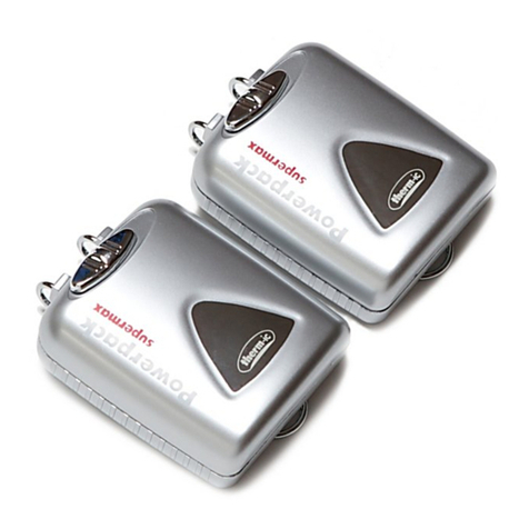
GROUPES DE PILOTAGE REVERSIBLES – DEBIT FIXE
REVERSIBLE POWER PACKS – FIXED FLOW RATE
Instructions de montage Mounting instructions
GROUPE RV07
RV07 POWER PACK
1. Positionner et fixer le groupe RV07 à l'emplacement choisi
selon notre paragraphe "Recommandations importantes".
2. Dévisser les 3 bouchons ¼ BSPP (L, M et M’) et procéder
au raccordement hydraulique selon notre paragraphe
"Schéma de câblage hydraulique".
3. Procéder au branchement électrique selon notre
paragraphe "Schéma de câblage électrique".
1. Position and secure the RV07 power pack at the selected location
by following the instructions in paragraph “Important
Recommendations”.
2. Undo the 3 ¼ BSPP plugs (L, M and M’) and proceed with the
hydraulic connections by following the instructions in paragraph
“Hydraulic Connection Drawing”.
3. Connect the electric wiring by following the instructions in
paragraph “Electric Connection Drawing”.
A B C D E F G Ø H I J K L M – M’
RV07
80 98 210 24 39 65 4 6,5 21 90 122 1/4
BSPP
1/4
BSPP
3

GROUPES DE PILOTAGE REVERSIBLES – DEBIT REGLABLE
REVERSIBLE POWER PACKS – ADJUSTABLE FLOW RATE
Instructions de montage Mounting instructions
GROUPES RV1 – RV2 – RV3
RV1 – RV2 – RV3 POWER PACKS
1.Positionner et fixer le groupe RV1, RV2 ou RV3 à
l'emplacement choisi selon notre paragraphe
"Recommandations importantes".
2.Dévisser les 3 bouchons ¼ BSPP (L, M et M’) et procéder
au raccordement hydraulique selon notre paragraphe
"Schéma de câblage hydraulique".
3.Procéder au branchement électrique selon notre paragraphe
"Schéma de câblage électrique".
1. Position and secure the RV1, RV2 or RV3 power pack at the
selected location by following the instructions in paragraph
“Important Recommendations”.
2. Undo the 3 ¼ BSPP plugs (L, M and M’) and proceed with the
hydraulic connections by following the instructions in paragraph
“Hydraulic Connection Drawing”.
3. Connect the electric wiring by following the instructions in
paragraph “Electric Connection Drawing”.
A B C D E F G Ø H I J K L M – M’
RV1 / RV2 / RV3 80 98 300 24 39 70 4 6,5 104 97 117 1/4
BSPP
1/4
BSPP
4

GROUPES DE PILOTAGE A ELECTROVANNES – DEBIT REGLABLE
POWER PACKS WITH ELECTROVALVES – ADJUSTABLE FLOW RATE
Instructions de montage Mounting instructions
GROUPES EV2 - EV3 - HVR
EV2 – EV3 – HVR POWER PACKS
1.Positionner et fixer le groupe EV2, EV3 ou HVR à
l'emplacement choisi selon notre paragraphe
"Recommandations importantes".
2.Dévisser les 3 bouchons ¼ BSPP (Let 2 x M) et procéder
au raccordement hydraulique selon notre paragraphe
"Schéma de câblage hydraulique".
3.Procéder au branchement électrique selon notre paragraphe
"Schéma de câblage électrique".
1. Position and secure the EV2, EV3 or HVR power pack at the
selected location by following the instructions in paragraph
“Important Recommendations”.
2. Undo the 3 ¼ BSPP plugs (Land 2 x M) and proceed with the
hydraulic connections by following the instructions in paragraph
“Hydraulic Connection Drawing”.
3. Connect the electrical wiring by following the instructions in
paragraph “Electric Connection Drawing”.
A B C D E F G Ø H I J K L M N
EV2 /
EV3
80 98 305 24 39 182 4 6,5 104 220 230 1/4
BSPP
1/4
BSPP
3/8
BSPP
HVR 100 115 440 80 100 179 4 7 267 239 230 1/4
BSPP
1/4
BSPP
3/8
BSPP
5

GROUPES DE PILOTAGE A ELECTROVANNES – DEBIT FIXE
POWER PACKS WITH ELECTRO-VALVES FOR AUTOPILOTS – FIXED FLOW
Instructions de montage Mounting instructions
CENTRALE HYDRAULIQUE H.F.
HYDRAULIC H.F. UNIT
1.Positionner et fixer la centrale hydraulique HF à
l'emplacement choisi selon notre paragraphe
"Recommandations importantes".
2.Dévisser les 3 bouchons (G et 2 x F) et procéder au
raccordement hydraulique selon notre paragraphe "Schéma
de câblage hydraulique".
3.Procéder au branchement électrique selon notre paragraphe
"Schéma de câblage électrique".
1.
Position and secure the HF electro-hydraulic unit at the selected
location by following the instructions in paragraph "Important
Recommandations".
2.
Undo the 3 plugs (Gand 2 x F) and proceed with the hydraulic
connections by following the instructions in paragraph "Hydraulic
Connection Drawing".
3.
Proceed with the electric connections by following the instructions
in paragraph "Electric Connection Drawing".
MASSE
/ MASS A B C D E F G H
HF 1 - 2,5
HF 1 - 3
HF 1 - 4 35 kg 750 460 220 125 140 3/8
BSPP
3/8
BSPP
1/2
BSPP
HF 1 - 6 45 kg 750 560 270 225 140 3/8
BSPP
3/8
BSPP
1
BSPP
HF 1,5 - 9 57 kg 750 560 270 225 140 3/8
BSPP
3/8
BSPP
1
BSPP
HF 1,5 - 11 57 kg 770 560 270 225 140 3/8
BSPP
3/8
BSPP
1
BSPP
HF 1,5 - 15
HF 1,5 - 18 62 kg 810 785 270 450 160 1/2
BSPP
1/2
BSPP
1
BSPP
6

S
CHEMAS DE CABLAGES HYDRAULIQUES DES GROUPES
RV07
–
RV1
–
RV2
–
RV3
HYDRAULIC CONNECTION DRAWINGS FOR
RV07
–
RV1
–
RV2
–
RV3
POWER PACKS
1
Pompe manuelle
Manual helm pump
2
Groupe
Power pack
3
Raccords drain
Drain fittings
4
Raccords d’utilisation
Outlets fittings
5
Tés égaux
Equal tee fittings
Simple commande
Single Steering Station Quantité
Quantity
1 1 2 4 2
Double commande
Twin Steering Station Quantité
Quantity
2 1 3 6 5
Couple de serrage raccords
Tightening Torque for Fittings
1/8 BSPP 1/4 BSPP 3/8 BSPP 1/2 BSPP
( Nm) 3 7,57 35 62
Montage simple commande / Single Steering Station Installation Montage double commande / Twin Steering Station Installation
7

S
CHEMAS DE CABLAGES HYDRAULIQUES DES GROUPES
EV2
–
EV3
–
HVR
1/3
HYDRAULIC CONNECTION DRAWINGS FOR
EV2
–
EV3
–
HVR
1/3
POWER PACKS
1
Pompe manuelle
Manual helm pump
2
Groupe
Power pack
3
Raccords drain
Drain fittings
4
Raccords d’utilisation
Outlets fittings
5
Tés égaux
Equal tee fittings
Simple commande
Single Steering Station Quantité
Quantity
1 1 2 4 2
Double commande
Twin Steering Station Quantité
Quantity
2 1 3 6 5
Couple de serrage raccords
Tightening Torque for Fittings
1/8 BSPP 1/4 BSPP 3/8 BSPP 1/2 BSPP
( Nm) 3 7,57 35 62
Montage simple commande / Single Steering Station Installation Montage double commande / Twin Steering Station Installation
8

S
CHEMAS DE CABLAGES HYDRAULIQUES DES GROUPES
HF
HYDRAULIC CONNECTION DRAWINGS FOR
HF
UNITS
1
Pompe manuelle
Manual helm pump
2
Groupe
Power pack
3
Raccords drain
Drain fittings
4
Raccords d’utilisation
Outlets fittings
5
Tés égaux
Equal tee fittings
Simple commande
Single Steering Station Quantité
Quantity
1 1 2 4 2
Double commande
Twin Steering Station Quantité
Quantity
2 1 3 6 5
Couple de serrage raccords
Tightening Torque for Fittings
1/8 BSPP 1/4 BSPP 3/8 BSPP 1/2 BSPP
( Nm) 3 7,57 35 62
Montage simple commande / Single Steering Station Installation Montage double commande / Twin Steering Station Installation
9

TYPES DE RACCORDEMENTS
•Par collier de serrage
•Par raccord à visser
•Par raccord à sertir
•Par raccord et flexible présertis
TYPES OF CONNECTION
•Clamp fitting
•Screwed connection
•Crimp connection
•Swaged Fittings and Flexible Tubes with Swaged Fittings
Par collier de serrage
Clamp fitting
Figure A :
Séparer l’écrou tournant et la pipette crantée
du raccord du groupe.
Visser la partie raccord sur les utilisations du
groupe en respectant les couples de serrage
indiqués.
Graisser la pipette crantée.
Passer le flexible dans le collier.
Emmancher le flexible sur la pipette crantée
jusqu’à 1 mm de l’écrou tournant.
Drawing A :
Loosen the swivel nut and the pipette from the
fitting for the power pack.
Screw the fitting (union piec
e) in the power pack
outlets as per the indicated torque.
Grease the notched pipette.
Insert the tube through the clamp.
Push the tube on the notched pipette up to 1 mm
from the swivel nut.
Figure B :
Placer le collier à environ 3 à 5 mm de la face
de l’écrou tournant et le sertir.
Remonter l’écrou tournant sur le raccord du
groupe (couple de serrage 6 Nm) tout en
maintenant le raccord avec une clé plate.
Drawing B :
Move the clamp to approx. 3 to 5 mm from the
swivel nut and crimp it.
Tighten the swivel nut on the fitting, while
holding the fitting with a spanner (torque = 6
N.m).
Raccords
Ne pas utiliser de raccords coniques.
Sertissage des flexibles
La coupe des flexibles devra être franche et perpendiculaire.
Ne pas couper les flexibles trop courts : tenir compte du
déplacement du vérin et des rayons de courbure
minimum (R 90 mm).
Aucune impureté ne doit pénétrer dans les flexibles.
Fittings
Do not use conic fittings.
Crimping of Flexible Tubes
Make a clean and perpendicular cut on the flexible tubes.
Do not cut them too short to allow for the cylinder motion
and the minimum bending radius of the pipes (R 90 mm).
No impurities are to enter the pipes.
10

Par raccord à visser
Screwed connection
Séparer l’écrou tournant, la douille et la nipple du raccord du groupe.
Visser la partie raccord sur les utilisations du groupe en respectant les
couples de serrage indiqués (voir schéma de cablage).
Tracer un repère à 21 mm pour ∅int. 8 mm ou à 30 mm pour ∅int. 10 mm
(Fig. C).
Huiler le bout du flexible et le bloquer en rotation sans l’écraser (Fig. D).
Visser la douille jusqu’au repère, sens de rotation anti-horaire (Fig. D).
Placer la douille dans l’étau (Fig. E) et huiler la nipple.
Visser la nipple jusqu’à lalimitedu filetage, sens de rotation horaire (Fig. F).
Separate the swivel nut, the sleeve and the nipple from the fitting for the power pack.
Screw the fitting (union piece)in the power pack outlets as per the indicated torque
(see hydraulic connection drawing).
Mark a point of reference at 21 mm for 8 mm inner Ø tube or 30 mm for 10 mm
inner Ø tube (Dwg C).
Lubricate the end of the tube and immobilize it without squeezing it (Dwg D).
Screw the sleeve up to the marking in anticlockwise direction (Dwg D).
Immobilize the sleeve in a vice (Dwg E) and lubricate the nipple.
Screwthenippletothethreadendinclockwisedirect
ion(
Dwg F
).
Par raccord à sertir
Crimp connection
Séparer l’écrou tournant et la bague des raccords du groupe.
Visser la partie raccords sur les utilisations du groupe en respectant les
couples de serrage indiqués (voir schéma de cablage).
Glisser l’écrou tournant et la bague sur le tube (Fig. G).
Visser l’écrou tournant jusqu’en début de butée (Fig. H).
Enfoncer fermement le tube dans le corps du raccord jusqu’en butée.
Puis à l’aide d’une clé, serrer l’écrou tournant d’environ 1 ½ tour (Fig. I).
Contrôle : démonter l’écrou tournant. Une collerette visible doit remplir
l’espace situé devant la face avant de l’arête. La bague peut tourner,
mais aucun déplacement axial n’est autorisé (Fig. J).
Remontage : visser l’écrou tournant sur le raccord jusqu’en début de
butée puis serrer d’environ 1/8 de tour à l’aide d’une clé.
Separate the swivel nut and the ring from the fittings for the power pack.
Screw the fittings (union pieces) in the power pack outlets as per the indicated
torque. (See hydraulic connection drawing).
Slip the swivel nut and the ring on the tube (Dwg G).
Screw on the swivel nut until it makes contact. Do not tighten. (Dwg H).
Firmly insert the tube inside the fitting until it comes to a stop. Tighten the
swivel nut with a spanner by approximately 1 ½ turn (Dwg I).
Checking: loosen the swivel nut. A visible flange must occupy the space in front of
the edge front face. The ring can turn but no axial movement is allowed (Dwg J).
Reassembly: screw on the swivel nut until it makes contact, then tighten it by
about 1/8 turn with a spanner.
11

Par raccord et flexible présertis
Swaged Fittings and Flexible Tubes with Swaged Fittings
Enlever les bouchons de protection livrés sur le groupe et les raccords.
Visser le raccord sens horaire, joint du raccord vers le groupe puis le
serrer.
1/8’ BSPP 1/4’ BSPP 3/8’ BSPP 1/2’ BSPP
" Nm 9 35 45 65
Enlever le bouchon de protection du flexible.
Visser le flexible sens horaire sur le raccord puis le serrer.
Répéter la même opération avec l’autre flexible.
Série raccord 10 L 12 L 15 L 17 L
" Nm 35 45 55 65
Série raccord 18 L 21 L JIC 7/8 JIC 9/16
" Nm 65 90 85 28
Série Ø lexible DN8 DN10 DN13 DN16 DN19
Rayon courbure mini
(mm) 90 110 150 175 215
Remove the protective caps supplied with the power pack and fittings.
Screw the fitting clockwise into the pump with the fitting seal on the power
pack side then tighten it.
1/8’ BSPP 1/4’ BSPP 3/8’ BSPP 1/2’ BSPP
" Nm 9 35 45 65
Remove the protective cap from the flexible tube.
Screw the flexible tube clockwise on the fitting and tighten it.
Repeat the same operation with the other flexible tube.
Fittings Range 10 L 12 L 15 L 17 L
" Nm 35 45 55 65
Fittings Range 18 L 21 L JIC 7/8 JIC 9/16
" Nm 65 90 85 28
Flexible tubes Range Ø DN8 DN10 DN13 DN16 DN19
Minimum Bending
Radius (mm) 90 110 150 175 215
12

S
CHEMA DE CABLAGE ELECTRIQUE DES GROUPES
RV07
–
RV1
–
RV2
–
RV3
ELECTRIC CONNECTION DRAWING FOR
RV07
–
RV1
–
RV2
–
RV3
POWER PACKS
RV07 RV1 RV2 RV3
Protection conseillée
Recommended protection
12 V 16 A 16 A 25 A 30 A
24 V 6 A 6 A 16 A 16 A
Section fil (*)
Wire Cross Section (*)
12 V 4 mm
2
/ sq.mm
6 mm
2
/ sq.mm
6 mm
2
/ sq.mm
10 mm
2
/ sq.mm
24 V 2,5 mm
2
/ sq.mm
4 mm
2
/ sq.mm
4 mm
2
/ sq.mm
4 mm
2
/ sq.mm
(*) longueur maxi
: 5 mètres / maximum length : 5 meters
! Toutes les opérations de branchement
décrites ci-dessous doivent s’effectuer en
ayant pris soin de couper l’alimentation
électrique.
Ne jamais faire tourner les groupes sans huile.
1.S’assurer que la tension d’alimentation (12 ou
24 V) correspond à la tension indiquée sur le
moteur.
2.Connecter la ½ prise Afournie avec le groupe
sur les fils d’alimentation électrique C.
3.Emboîter les ½ prises Aet Bsans tenir
compte des polarités +et –
4.Mettre le circuit électrique sous tension.
5.Procéder à la mise en route du pilote selon les
instructions de son fabricant.
6.Si le moteur du groupe tourne dans le mauvais
sens (déplacement du vérin contraire à celui
demandé), inverser les polarités +et –dans la
½ prise A.
!
All the electrical connections below must
be carried out once the electrical supply has
been cut off.
Never run the power packs without oil.
1. Check that the serviceable voltage on the boat (12
or 24 V) is the same as the one specified on the
motor.
2. Connect the “half plug” Asupplied with the
power pack to the electric wires C.
3. Fit together both “half-plugs” Aand Bwithout
taking into account the +and –polarities.
4. Turn the power on.
5. Put the autopilot electronics into service as per
the manufacturer’s instructions.
6. If the power pack motor turns the wrong way
round (motion of the cylinder in the wrong
direction), simply inverse +and –polarities in
the “half-plug” A.
13

S
CHEMA DE CABLAGE ELECTRIQUE DES GROUPES
EV2
–
EV3
–
HVR
1/3
–
HF
ELECTRIC CONNECTION DRAWING FOR
EV2
–
EV3
–
HVR
1/3
–
HF
POWER PACKS
EV2 EV3 HVR 1/3 HF 1 HF 1,5
Protection conseillée
Recommended
protection
Moteur
Motor 12 V 25 A 30 A 32 A
24 V 16 A 16 A 20 A 50 A 100 A
Electro-distributeur
Electro-distributor 12 V 2 A 2 A 2 A
24 V 1 A 1 A 1 A 1 A 1 A
Section fil (*)
Wire Cross Section (*)
Moteur
Motor 12 V 6 mm
2
/ sq.mm
10 mm
2
/ sq.mm
10 mm
2
/ sq.mm
24 V 4 mm
2
/ sq.mm
4 mm
2
/ sq.mm
4 mm
2
/ sq.mm
16 mm
2
/ sq.mm
25 mm
2
/ sq.mm
Electro-distributeur
Electro-distributor 12 V 0,75 mm
2
/ sq.mm
0,75 mm
2
/ sq.mm
0,75 mm
2
/ sq.mm
24 V 0,75 mm
2
/ sq.mm
0,75 mm
2
/ sq.mm
0,75 mm
2
/ sq.mm
0,75 mm
2
/ sq.mm
0,75 mm
2
/ sq.mm
(*) longueur maxi : 5 mètres / maximum length : 5 meters
B
RANCHEMENT DE LA PARTIE
:
E
LECTRO
-
DISTRIBUTEUR
/
C
ONNECTION OF THE
E
LECTRO
-D
ISTRIBUTOR
! Toutes les opérations de branchement
décrites ci-dessous doivent s’effectuer en
ayant pris soin de couper l’alimentation
électrique.
Ne jamais faire tourner les groupes sans huile.
1.S’assurer que la tension d’alimentation (12 ou
24 V) correspond à la tension indiquée sur
l’électro-distributeur.
2.Brancher les extrémités des câbles préconisés
par le fabricant du calculateur sur les prises
femelles Aet a(Alimentation : bornes en U,
aucune polarité à respecter). Raccorder les
autres extrémités des câbles sur le calculateur.
3.Emboîter les prises femelles Aet asur les
prises mâles Ben veillant à bien positionner
les joints d’étanchéité C. Bloquer l’ensemble à
l’aide des vis D.
! Lors de la mise en route du pilote, si le
vérin se déplace dans le mauvais sens,
inverser les prises femelles Aet a.
!
All the electrical connections below must
be carried out once the electrical supply has
been cut off.
Never run the power packs without oil.
1. Check that the serviceable voltage (12 or 24 V) is
identical to the one indicated on the electro-
distributor.
2. Connect the electrical wires as specified by the
autopilot manufacturer to the female connectors
A
and
a
(Power supply: U-shaped terminals,
irrespective of polarity). Connect the other wire
ends to the autopilot computer.
3. Fit together female plugs
A
and
a
on male
plugs
B. Make sure
that seals
C
are correctly
positioned. Secure the assembly with screws
D
.
!
When starting the autopilot, invert female
plugs Aand a if the cylinder moves in the
wrong direction.
14

B
RANCHEMENT DE LA PARTIE
:
M
OTEUR DES GROUPES
EV2,
EV3,
HVR
1/3
/
C
ONNECTION OF THE POWER PACK MOTOR ON
EV2,
EV3,
HVR
1/3
! Toutes les opérations de branchement
décrites ci-dessous doivent s’effectuer en ayant
pris soin de couper l’alimentation électrique.
Ne jamais faire tourner les groupes sans huile.
1.S’assurer que la tension d’alimentation (12 ou
24 V) correspond à la tension indiquée sur le
moteur.
2.Connecter la ½ prise Afournie avec le groupe
sur les fils d’alimentation électrique Cen
tenant compte des polarités +et –de la ½
prise B.
3. Emboîter les ½ prises Aet B.
4.Mettre le circuit électrique sous tension.
5.Procéder à la mise en route du pilote selon les
instructions de son fabricant.
!
All the electrical connections below must
be carried out once the electrical supply has
been cut off.
Never run the power packs without oil.
1. Check that the serviceable voltage on the boat (12
or 24 V) is the same as the one specified on the
motor.
2. Connect the “half plug” A supplied with the
power pack to the electric wires C in compliance
with the + and – polarities in “half plug” B.
3. Fit together both “half-plugs” Aand B.
4. Turn the power on.
5. Put the autopilot electronics into service as per
the manufacturer’s instructions.
B
RANCHEMENTDELAPARTIE
:
M
OTEURDESGROUPES
HF
/
C
ONNECTIONOFTHE
HF
UNIT
MOTOR
! Toutes les opérations de branchement
décrites ci-dessous doivent s’effectuer en ayant
pris soin de couper l’alimentation électrique.
Ne jamais faire tourner les groupes sans huile.
1.S’assurer que la tension d’alimentation
correspond à la tension indiquée sur le moteur.
2.Connecter les fils électriques Aet aaux
bornes du boitier Ben respectant les polarités
+(borne avec fil rouge) et –(borne avec fil
bleu ou noir).
3.Fermer le boitier Bavec son couvercle Cen
veillant à bien positionner le joint d’étanchéité
D. Bloquer l’ensemble à l’aide des 4 vis E.
4.Mettre le circuit électrique sous tension.
5.Procéder à la mise en route du pilote selon les
instructions de son fabricant.
!
All the electrical connections below must
be carried out once the electrical supply has
been cut off.
Never run the power packs without oil.
1. Check that the serviceable voltage on the boat is
the same as the one specified on the motor.
2. Connect the electric wires Aand A’ to the
terminals on block Bby observing the polarities
+(red wire) and –(blue or black wire).
3. Close the block Bwith its cover C. Make sure
that seal Dis correctly positioned. Secure the
assembly with 4 screws E.
4. Turn the power on.
5. Put the autopilot electronics into service as per
the manufacturer’s instructions.
15

REMPLISSAGE ET PURGE DE VOTRE SYSTEME
Simple poste de pilotage + groupe
Double poste de pilotage + groupe
Opérations finales simple et double poste de pilotage
FILLING UP AND BLEEDING THE SYSTEM
Single steering Station System + Power Pack
Twin Steering Station System + Power Pack
Final Operations for Single and Double Steering Station Systems
Simple poste de pilotage + groupe RV07, RV1, RV2, RV3
Single Steering Station System + Power Pack RV07, RV1, RV2, RV3 Double poste de pilotage + groupe RV07, RV1, RV2, RV3
Twin Steering Station System + Power Pack RV07, RV1, RV2, RV3
Only use LS oil or oil with ISO 22 viscosity.
Make sure that the hydraulic piping is perfectly clean
and keep the oil free from impurities which may cause
the deterioration of the components of the hydraulic
steering system.
Utiliser uniquement de l’huile LS ou de l’huile de
viscosité ISO 22.
Assurez vous dans tous les cas que votre
tuyauterie et votre huile restent parfaitement
propres, toutes impuretés pouvant entraîner une
détérioration des organes de la direction
hydraulique.
16

Simple poste de pilotage
+ groupe RV07, RV1, RV2, RV3
Single Steering Station System
+ Power Pack RV07, RV1, RV2, RV3
Brancher les flexibles d’utilisation sur la pompe manuelle et le groupe et
plonger l’autre extrémité des flexibles dans un récipient d’huile.
Brancher le drain entre la pompe manuelle et le groupe.
Installer une réserve sur la pompe manuelle et la maintenir
constamment remplie d’huile pendant la purge du circuit.
Groupe RV07 : débrancher le flexible drain coté groupe. Lorsque l’huile
coule sans air, rebrancher le flexible.
Groupes RV1, RV2, RV3 : ouvrir le purgeur du groupe (1 tour). Lorsque
l’huile coule sans air, refermer le purgeur ( 3,5 Nm).
Faire tourner la pompe manuelle lentement côté tribord (environ 15 tours
en fonction de la longueur de votre circuit), puis faire tourner le groupe
(même sens de rotation que la pompe manuelle) pendant 10 à 15
secondes. Repérer le flexible de refoulement lorsqu’il ne rejette plus d’air
(voir schéma).
Faire tourner le groupe côté babord (en inversant le sens de rotation)
pendant 10 à 15 secondes, puis la pompe manuelle côté bâbord (environ
15 tours), ceci jusqu’à ce qu’il n’y ait plus d’air qui sorte du flexible non
repéré.
Positionner le vérin, tige entièrement sortie côté tribord de votre bateau.
Connect the utilisation pipes to the manual helm pump and the power
pack. Plunge the other pipe ends into an oil container.
Connect a drain between the manual pump and the power pack.
Put an oil container on the oil filler neck of the manual helm pump and
keep it full of oil during the bleeding process.
Power pack RV07: disconnect the drain on the power pack. When the oil
that comes out is free of air bubbles, connect the drain again.
Power packs RV1, RV2, RV3: open the bleeder cock on the power pack
(1 turn). When the oil that comes out is free of air bubbles, tighten the
bleeder cock ( 3.5 Nm).
Turn the manual pump slowly to starboard (around 15 wheel turns in
function of the hydraulic circuit length), then run the power pack (in the
same direction as the manual pump) during 10 to 15 seconds. Mark the
delivery pipe once there is no air coming out anymore (see drawing).
Run the power pack to port (by inversing the rotation direction) during
10 to 15 seconds, then turn the manual pump to port (around 15 turns)
until there is no air coming out of the unmarked pipe.
Position the cylinder with its rod out on the boat starboard side.
17

Brancher le flexible repéré au vérin, côté tige sortie.
!Ne pas ouvrir le purgeur du vérin côté tribord.
Brancher le flexible non repéré au vérin, côté tige rentrée et ouvrir le
purgeur du vérin côté bâbord.
Faire tourner la pompe manuelle lentement côté bâbord, puis le groupe
(même sens de rotation que la pompe). Lorsqu’il ne sort plus d’air du
purgeur du vérin côté bâbord, fermer le purgeur ( 3,5 Nm).
Ouvrir le purgeur du vérin côté tribord (côté tige sortie).
Faire tourner le groupe côté tribord, puis la pompe manuelle lentement,
également côté tribord. Lorsque la tige s’est déplacée sur toute sa course
et qu’il ne sort plus d’air du purgeur du vérin côté tribord, fermer le
purgeur ( 3,5 Nm).
Pour les opérations finales simple et double poste de pilotage, se reporter
à la rubrique
3
en fin de notice.
Connect the marked pipe to the cylinder on the side where the rod is out.
!Do not open the cylinder bleeder cock on starboard.
Connect the unmarked pipe to the cylinder on the side where the rod is
in. Open the bleeder cock on port.
Turn the manual pump slowly to port and then run the power pack (in the
same direction as the pump). When the oil coming out from the cylinder
port bleeder cock is free of air bubbles, close the bleeder cock ( 3,5 Nm).
Open the cylinder bleeder cock on starboard (side where the cylinder rod is
out.)
Run the power pack to port and then turn the manual helm pump slowly to port
also. Once the cylinder rod has travelled its complete stroke and the air coming
out ofthecylinder starboard bleeder cock is freeof air bubbles, close the
bleeder cock ( 3,5 Nm).
Please refer to paragraph
3
at the end of the manual for the final check list
for single or twin steering stations.
Double poste de pilotage
+ groupe RV07, RV1, RV2, RV3
Twin Steering Station System
+ Power Pack RV07, RV1, RV2, RV3
Brancher les flexibles d’utilisation sur les pompes manuelles et le groupe
et plonger l’autre extrémité des flexibles dans un récipient d’huile.
Brancher les drains entre les pompes manuelles et le groupe.
Installer une réserve sur la pompe manuelle supérieure et la
maintenir constamment remplie d’huile pendant la purge du circuit.
Ouvrir le bouchon de remplissage de la pompe inférieure et lorsque la
pompe est remplie d’huile remettre le bouchon.
Groupe RV07 : débrancher le flexible drain coté groupe. Lorsque l’huile
coule sans air, rebrancher le flexible.
Groupes RV1, RV2, RV3 : ouvrir le purgeur du groupe (1 tour). Lorsque
l’huile coule sans air, refermer le purgeur ( 3,5 Nm).
Connect the utilisation pipes to the manual helm pumps and the power
pack. Plunge the other pipe ends into an oil container.
Connect the drains between the manual pumps and the power pack.
Put an oil container on the oil filler neck of the upper manual helm
pump and keep it full of oil during the bleeding process.
Open the filler cap on the lower manual helm pump. Once the pump is
full of oil, put the filler cap back on.
Power pack RV07: disconnect the drain on the power pack. When the oil
that comes out is free of air bubbles, connect the drain again.
Power packs RV1, RV2, RV3: open the bleeder cock on the power pack
(1 turn). When the oil that comes out is free of air bubbles, tighten the
bleeder cock ( 3.5 Nm).
18

Faire tourner la pompe manuelle supérieure lentement côté tribord
(environ 15 tours en fonction de la longueur de votre circuit), puis la
pompe manuelle inférieure lentement côté tribord (environ 15 tours en
fonction de la longueur de votre circuit). Faire tourner le groupe (même
sens de rotation que les pompes manuelles) pendant 10 à 15 secondes.
Repérer le flexible de refoulement lorsqu’il ne rejette plus d’air (voir
schéma).
Faire tourner le groupe côté babord en inversant le sens de rotation
pendant 10 à 15 secondes. Faire tourner la pompe manuelle inférieure
côté bâbord (environ 15 tours en fonction de la longueur de votre circuit),
puis la pompe manuelle supérieure côté bâbord (environ 15 tours en
fonction de la longueur de votre circuit), jusqu’à ce qu’il n’y ait plus d’air
qui sorte du flexible non repéré.
Positionner le vérin, tige entièrement sortie côté tribord de votre bateau.
Brancher le flexible repéré au vérin, côté tige sortie.
! Ne pas ouvrir le purgeur du vérin côté tribord.
Brancher le flexible non repéré au vérin, côté tige rentrée et ouvrir le
purgeur du vérin côté bâbord.
Faire tourner la pompe manuelle supérieure lentement côté bâbord, puis
la pompe manuelle inférieure et ensuite le groupe (même sens de
rotation que les pompes). Lorsqu’il ne sort plus d’air du purgeur du vérin
côté bâbord, fermer le purgeur ( 3,5 Nm).
Ouvrir le purgeur du vérin côté tribord (côté tige sortie).
Faire tourner le groupe côté tribord, puis la pompe manuelle inférieure
lentement côté tribord et ensuite la pompe manuelle supérieure côté
tribord. Lorsque la tige du vérin s’est déplacée sur toute sa course et qu’il
ne sort plus d’air du purgeur du vérin côté tribord, fermer le purgeur du
vérin ( 3,5 Nm).
Pour l
es opérations finales simple et double poste de pilotage, se reporter
à la rubrique 3en fin de notice.
Turn the upper manual pump slowly to starboard (around 15 wheel turns
in function of the hydraulic circuit length), then turn the lower manual
pump slowly to starboard (around 15 wheel turns in function of the
hydraulic circuit length). Run the power pack (in the same direction as
the manual pumps) during 10 to 15 seconds. Mark the delivery pipe once
there is no air coming out anymore (see drawing).
Run the power pack to port by inversing the rotation direction during 10
to 15 seconds, then turn the lower manual helm pump to port (around 15
turns in function of the hydraulic circuit length). Then turn the upper
manual helm pump to port (around 15 turns in function of the hydraulic
circuit length) until there is no air coming out of the unmarked pipe.
Position the cylinder with its rod out on the boat starboard side.
Connect the marked pipe to the cylinder on the side where the rod is out.
!
Do not open the cylinder bleeder cock on starboard.
Connect the unmarked pipe to the cylinder on the side where the rod is in.
Open the bleeder cock on port.
Turn the upper manual pump slowly to port, then the lower manual pump
and then run the power pack (in the same direction as the pumps). When
the oil coming out from the cylinder port bleeder cock is free of air
bubbles, close the bleeder cock ( 3,5 Nm).
Openthecylinderbleedercockon starboard(sidewherethe cylinder rod isout).
Run the power pack to starboard, then turn the lower manual helm pump slowly
to starboard also, then turn the upper manual pump in the same direction. Once
the cylinder rod has travelled its complete stroke and the air coming out of the
cylinder starboard bleeder cock is free of air bubbles, close the bleeder cock (
3,5 Nm).
Please refer to paragraph 3 at the end of the manual for the final check
list for single or twin steering stations.
19
This manual suits for next models
14
Table of contents