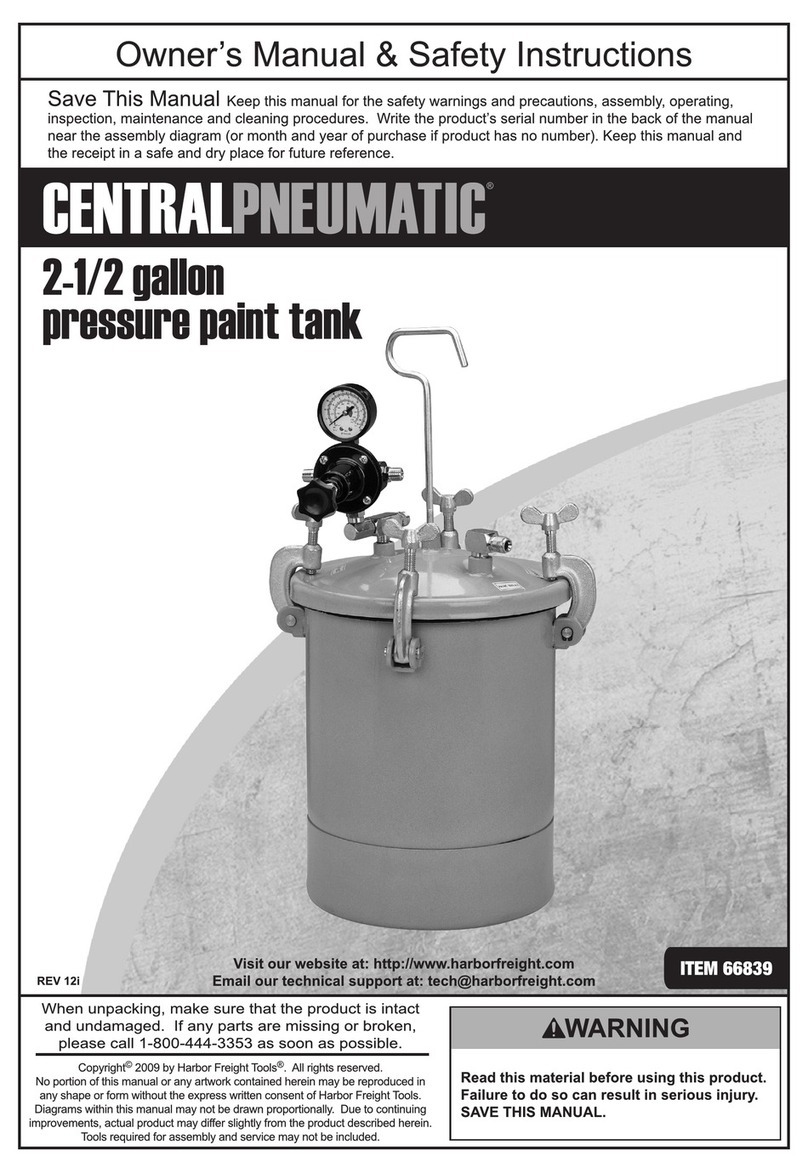
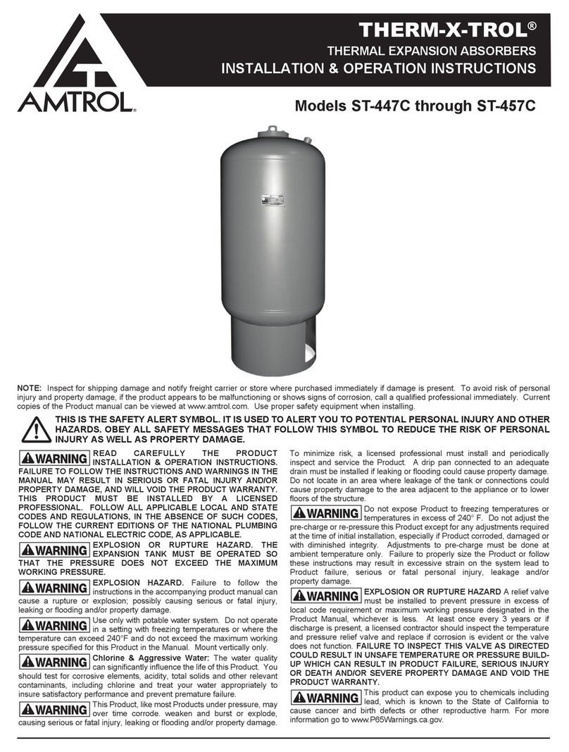
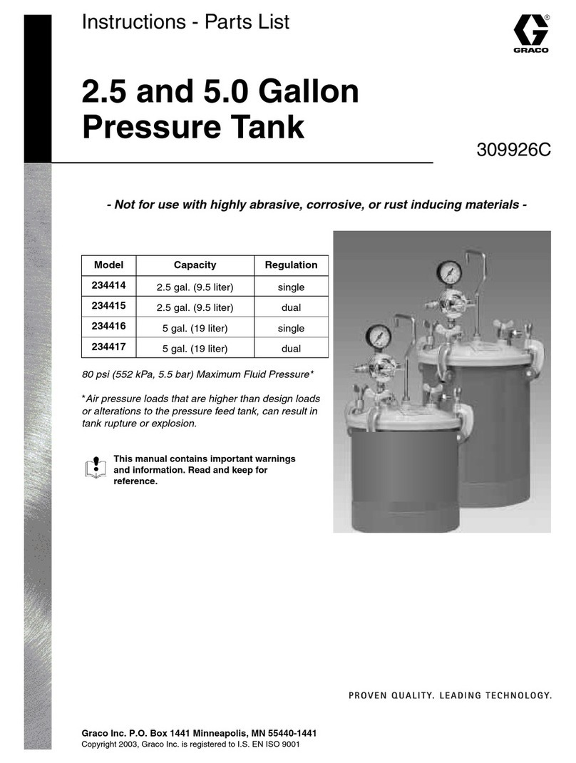
Graco SHARPE A Series Parts list manual

Instructions-Parts
2.5 Gallon
Pressure Tank 313291D
ENG
(Non-ASME Design)
For low-pressure painting and coating applications requiring portability, small batches, or
frequent color changes
50 psi (350 kPa, 3.5 bar) Maximum Working Pressure
Model 24A555, Series A (shown)
Basic portable pressure tank
Model 24A557, Series A
with dual regulators
Important Instructions
Read all warnings and instructions in this manual.
Save these instructions.
TI12983a

2313291D
Contents
Warnings . . . . . . . . . . . . . . . . . . . . . . . . . . . . . . . . . 3
Installation . . . . . . . . . . . . . . . . . . . . . . . . . . . . . . . . 4
Grounding . . . . . . . . . . . . . . . . . . . . . . . . . . . . . . 4
Setup . . . . . . . . . . . . . . . . . . . . . . . . . . . . . . . . . . 5
Operation . . . . . . . . . . . . . . . . . . . . . . . . . . . . . . . . . 6
Pressure Relief Procedure . . . . . . . . . . . . . . . . . 6
Fill the Tank . . . . . . . . . . . . . . . . . . . . . . . . . . . . . 6
Adjust the Air Regulators . . . . . . . . . . . . . . . . . . 6
Vertical and Horizontal Reach . . . . . . . . . . . . . . . 6
Cleaning and Maintenance . . . . . . . . . . . . . . . . . . . 7
Technical Data . . . . . . . . . . . . . . . . . . . . . . . . . . . . . 7
Parts . . . . . . . . . . . . . . . . . . . . . . . . . . . . . . . . . . . . . 8
Sharpe 1 Year Limited Warranty . . . . . . . . . . . . . . 10
Sharpe Information . . . . . . . . . . . . . . . . . . . . . . . . 10
Product Registration . . . . . . . . . . . . . . . . . . . . . . . 10

Warnings
313291D 3
Warnings
The following warnings are for the setup, use, grounding, maintenance, and repair of this equipment. The exclama-
tion point symbol alerts you to a general warning and the hazard symbol refers to procedure-specific risk. Refer back
to these warnings. Additional, product-specific warnings may be found throughout the body of this manual where
applicable.
WARNINGWARNINGWARNING
WARNING
FIRE AND EXPLOSION HAZARD
Flammable fumes, such as solvent and paint fumes, in work area can ignite or explode. To help prevent
fire and explosion:
• Use equipment only in well ventilated area.
• Eliminate all ignition sources; such as pilot lights, cigarettes, portable electric lamps, and plastic drop
cloths (potential static arc).
• Keep work area free of debris, including solvent, rags and gasoline.
• Do not plug or unplug power cords or turn lights on or off when flammable fumes are present.
• Ground all equipment in the work area. See Grounding instructions.
• If there is static sparking or you feel a shock, stop operation immediately. Do not use equipment
until you identify and correct the problem.
• Keep a working fire extinguisher in the work area.
EQUIPMENT MISUSE HAZARD
Misuse can cause death or serious injury.
• Do not operate the unit when fatigued or under the influence of drugs or alcohol.
• Do not exceed the maximum working pressure or temperature rating of the lowest rated system
component. See Technical Data in all equipment manuals.
• Use fluids and solvents that are compatible with equipment wetted parts. See Technical Data in all
equipment manuals. Read fluid and solvent manufacturer’s warnings. For complete information
about your material, request MSDS forms from distributor or retailer.
• Check equipment daily. Repair or replace worn or damaged parts immediately with genuine manu-
facturer’s replacement parts only.
• Do not alter or modify equipment.
• Use equipment only for its intended purpose. Call your distributor for information.
• Route hoses and cables away from traffic areas, sharp edges, moving parts, and hot surfaces.
• Do not kink or over bend hoses or use hoses to pull equipment.
• Keep children and animals away from work area.
• Comply with all applicable regulations.
PRESSURIZED EQUIPMENT HAZARD
Fluid from the gun/dispense valve, leaks, or ruptured components can splash in the eyes or on skin and
cause serious injury.
• Follow Pressure Relief Procedure in this manual, when you stop spraying and before cleaning,
checking, or servicing equipment.
• Tighten all fluid connections before operating the equipment.
• Check hoses, tubes, and couplings daily. Replace worn or damaged parts immediately.
TOXIC FLUID OR FUMES HAZARD
Toxic fluids or fumes can cause serious injury or death if splashed in the eyes or on skin, inhaled, or
swallowed.
• Read MSDS’s to know the specific hazards of the fluids you are using.
• Store hazardous fluid in approved containers, and dispose of it according to applicable guidelines.
• Always wear impervious gloves when spraying or cleaning equipment.

Installation
4313291D
Installation
Grounding
The equipment must be grounded. Grounding reduces
the risk of static and electric shock by providing an
escape wire for the electrical current due to static build
up or in the event of a short circuit.
Pump: connect the ground wire (A) firmly to a metal
part of the tank such as the swivel (B) at the base of the
regulator. Connect the other end of the wire to a true
earth ground. See FIG. 1. Order Part No. 237569
Ground Wire and Clamp.
Air compressor: follow manufacturer’s
recommendations.
Object being sprayed: follow local code.
Solvent pails used when flushing: follow local code.
Use only conductive metal pails, placed on a grounded
surface. Do not place the pail on a nonconductive sur-
face, such as paper or cardboard, which interrupts
grounding continuity.
To maintain grounding continuity when flushing or
relieving pressure: hold metal part of the spray gun
firmly to the side of a grounded metal pail, then trigger
the gun.
WARNINGWARNINGWARNING
WARNING
PRESSURIZED ALUMINUM PARTS HAZARD
Do not use 1,1,1-trichloroethane, methylene chloride, other halogenated hydrocarbon solvents or fluids
containing such solvents in pressurized aluminum equipment. Such use can cause serious chemical
reaction and equipment rupture, and result in death, serious injury, and property damage.
PERSONAL PROTECTIVE EQUIPMENT
You must wear appropriate protective equipment when operating, servicing, or when in the operating
area of the equipment to help protect you from serious injury, including eye injury, inhalation of toxic
fumes, burns, and hearing loss. This equipment includes but is not limited to:
• Protective eyewear
• Clothing and respirator as recommended by the fluid and solvent manufacturer
•Gloves
• Hearing protection
FIG. 1: Ground the equipment
ti12985a
B
A

Installation
313291D 5
Setup
• Single-Regulated Tank (Model 24A555): When
the air pressure to the tank and the spray gun atom-
izing air are controlled by one regulator, regulated
air controls the tank pressure and unregulated air is
supplied to the spray gun. See FIG. 3.
• Dual-Regulated Tank (Model 24A557): For sepa-
rate control of the atomizing air, a separate atomiz-
ing air regulator for the tank is supplied. See FIG. 4.
1. Install an air filter upstream from the regulator to
remove dirt and moisture from your air supply.
2. Screw the handle (B) and the nut (C) onto the cover,
and tighten them securely.
3. Screw the riser tube (E) into the pipe fitting on the
bottom side of the tank cover. See FIG. 2.
4. Screw the swivel union (2) into the port marked AIR
on the tank cover.
5. Assemble the air regulator (9). See page 8 for
Model 24A555, single-regulated tank. See page 9
for Model 24A557, dual-regulated tank.
6. Screw the assembled regulator into the swivel
union (2).
7. Connect an air supply hose to the 1/4 npt air inlet fit-
ting (9c-1). Connect the gun’s air atomizing hose to
fitting (9c-2). See FIG. 3 for single-regulated tanks.
See FIG. 4 for dual-regulated tanks.
8. Connect the gun’s fluid hose to the adapter (D) at
the point marked PAINT. See FIG. 2.
9. Connect the air atomizing and fluid hoses to the
gun. See FIG. 2.
NOTICE
Use thread sealant on all male threads.
FIG. 2: Typical installation
ti12984a
E
Fluid
Air
B
9
C
D
2
FIG. 3: Air connections for single-regulated tanks
FIG. 4: Air connections for dual-regulated tanks
ti12989a
9b
Air regulator
9c-2
Air to gun
9c-1
Air from
compressor
2
Air to tank
ti12991a
9b
Air regulator
9f
Atomizing
Air regulator
9c-1
Air from
compressor
9c-2
Air to gun
2
Air to tank

Operation
6313291D
Operation
Pressure Relief Procedure
1. Shut off the air supply to the tank.
2. Lift the pressure relief valve ring (1b) to open it. See
FIG. 5.
3. When no air is escaping through the valve, unscrew
the wing nuts and remove the tank cover (H).
4. Leave the pressure relief valve open until you have
reinstalled the cover.
Fill the Tank
1. Follow the manufacturer’s recommendations to pre-
pare the paint or other coating. Strain the paint to
remove particles or sediment that could clog the
spray gun and hose.
2. Follow Pressure Relief Procedure (above).
3. Unscrew the wing nuts and remove the cover (H).
4. Fill the tank with the paint. Leave at least 2 in.
(51 mm) between the paint level and the tank cover.
A one gallon paint can may be placed inside the
pressure tank.
5. Install the tank cover and evenly hand tighten the
wing nuts. Overtightening the nuts may cause the
gasket (1c) to squeeze out. The gasket is needed to
properly seal the cover and tank.
Adjust the Air Regulators
Turn the air regulator T handle counterclockwise all the
way to off. Turn on the master air supply. Adjust the air
regulators to the required pressure. Always use the low-
est pressure necessary to obtain the desired results.
Lower pressures help reduce spray tip wear.
Vertical and Horizontal Reach
Do not operate the spray gun more than 10 ft (3.1 m)
above the paint tank. Longer lengths of air and paint
hose may be used between the pressure tank and the
spray gun for greater horizontal working range.
Pressure tanks remain pressurized until pressure is
manually relieved.
NOTICE
Overfilling or tipping the tank causes the paint to
enter the air line and clog the regulator, hose, and
gun. Do not exceed the 2.5 gallon tank capacity.
FIG. 5
To reduce the risk of overpressurizing the tank, which
could result in component rupture and cause serious
injury, never exceed 50 psi (350 kPa, 3.5 bar) maxi-
mum air input pressure to the tank.
ti12987a
H
1b
1c

Cleaning and Maintenance
313291D 7
Cleaning and Maintenance
1. Follow the Pressure Relief Procedure, page 6.
2. Unscrew the wing nuts and remove the cover (H).
3. Loosen the retaining ring of the spray gun air cap
about three turns.
4. Hold a rag over the air cap and trigger the gun to
force the paint back through the hose and into the
tank.
5. Empty the tank.
6. Pour a compatible solvent into the tank.
7. Replace the cover and tighten the wing nuts evenly
and securely. Keep the wing nuts well greased so
they will screw down freely.
8. Remove the spray gun air cap.
9. Turn on the air supply. Trigger the gun into a waste
container until clean solvent comes from the gun.
10. Empty the solvent and wipe the inside of the tank
and equipment with a solvent-dampened rag.
11. Remove the riser tube (E) and clean it thoroughly.
12. Keep the pressure relief valve (1b) clean and in
working order. The relief valve is preset and locked
to release air automatically if pressure exceeds 50
psi (350 kPa, 3.5 bar).
Technical Data
NOTICE
Be sure the solvent you use is compatible with the
fluid being sprayed and the hose material. If paint comes in contact with the pressure relief
valve, remove and clean the valve thoroughly. If the
valve still doesn’t work properly, replace it with a new
one. Do not try to reset the valve.
Tank capacity . . . . . . . . . . . . . . . . . . . . . . . . . . . . . . . . . . 2.5 gallons (9.5 liters)
Maximum working pressure . . . . . . . . . . . . . . . . . . . . . . . 50 psi (350 kPa, 3.5 bar)
Pressure relief valve setting . . . . . . . . . . . . . . . . . . . . . . . 50 psi (350 kPa, 3.5 bar)
Air inlet size . . . . . . . . . . . . . . . . . . . . . . . . . . . . . . . . . . . 1/4 npt(m)
Fluid outlet size. . . . . . . . . . . . . . . . . . . . . . . . . . . . . . . . . 3/8 npsm(m)
Air outlet size . . . . . . . . . . . . . . . . . . . . . . . . . . . . . . . . . . 1/4 npt(m)
Height . . . . . . . . . . . . . . . . . . . . . . . . . . . . . . . . . . . . . . . . 21 in. (533 mm)
Weight . . . . . . . . . . . . . . . . . . . . . . . . . . . . . . . . . . . . . . . 11 lb (5 kg)
Wetted parts . . . . . . . . . . . . . . . . . . . . . . . . . . . . . . . . . . . Aluminum, brass, steel, buna-n, polyethylene

Parts
8313291D
Parts
Model 24A555, Pressure Tank with Single Regulator
----- Part is not sold separately.
1
ti12986a
ti12990a
9
2
1b
1
1c
not visible
9a
9b
9c
9d
2
9c
9c
ti12990a
Ref.
No. Part No. Description Qty.
1 ----- BARE PRESSURE TANK, includes
items 1a-1c
1
1a
112077
112078
TANK LINER, low density polyethyl-
ene (not shown)
5 pack of tank liners
25 pack of tank liners
1
1
1b 103996 VALVE, pressure relief; 50 psi
(350 kPa, 3.5 bar)
1
1c 244953 GASKET, cover, polyethylene
(package of 3)
1
2 156823 UNION, swivel 1
9 U10004 REGULATOR ASSEMBLY, includes
items 9a-9d)
1
9a 8220 GAUGE, air pressure, 0–100 psi
(0 to 700 kPa, 0–7 bar)
1
9b 1610 AIR REGULATOR, see manual
310605 for parts
1
9c 9993 FITTING, air inlet, 1/4 npt x 1/4 npt
straight
3
9d 119030 FITTING, reducer, 3/8 npt(m) x
1/4 npt(f)
1
Ref.
No. Part No. Description Qty.

Parts
313291D 9
Model 24A557, Pressure Tank with Dual Regulators
Part No/Description
----- Part is not sold separately.
Note: For single regulator use, replace fitting 9e with
fitting 9c from regulator 9f.
1
ti12988a
ti12992a
9a
9b
9c
9c
9c
9d
9f
9h
9g
9e
2
9
2
1c
not visible
1b
1
Ref.
No. Part No. Description Qty.
1 ----- BARE PRESSURE TANK, includes
items 1a-1c
1
1a
112077
112078
TANK LINER, low density polyethyl-
ene (not shown)
5 pack of tank liners
25 pack of tank liners
1
1
1b 103996 VALVE, pressure relief; 50 psi
(350 kPa, 3.5 bar)
1
1c 244953 GASKET, cover, polyethylene
(package of 3)
1
2 156823 UNION, swivel 1
9 U10004 REGULATOR ASSEMBLY, includes
items 9a-9d)
1
9a 8220 GAUGE, air pressure, 0–100 psi
(0-700 kPa, 0–7 bar)
1
9b 1610 AIR REGULATOR, see manual
310605 for parts
1
9c 9993 FITTING, air inlet, 1/4 npt x 1/4 npt
straight
3
9d 119030 FITTING, reducer, 3/8 npt(m) x
1/4 npt(f)
1
9e 157350 ADAPTER, 3/8 npt x 1/4 npt 1
9f 1630 AIR REGULATOR, see manual
310605 for parts
1
9g 8230 PRESSURE GAUGE 1
9h 10028 PLUG, regulator 1
Ref.
No. Part No. Description Qty.

All written and visual data contained in this document reflects the latest product information available at the time of publication.
Graco reserves the right to make changes at any time without notice.
Original instructions. This manual contains English. MM 313291
SHARPE MANUFACTURING • P.O. BOX 1441, MINNEAPOLIS, MN 55440-1441
Copyright 2008, Graco Inc. is registered to ISO 9001
1-800-742-7731, www.sharpe1.com
Revised 02/2011
Sharpe 1 Year Limited Warranty
Sharpe warrants this product to the original user against defective material or workmanship for a period of 1 year
from the date of purchase.
Sharpe reserves the right to determine whether the part or parts failed because of defective material, workmanship,
or other causes. Failures caused by accident, alteration, or misuse are not covered by this warranty.
Sharpe, at its discretion, will repair or replace products covered under this warranty free of charge. Repairs or
replacements of products covered under this warranty are warranted for the remainder of the original warranty
period.
Sharpe or its authorized service representatives must perform all warranty repairs. Any repair to the product by
unauthorized service representatives voids this warranty. The rights under this warranty are limited to the original
user and may not be transferred to subsequent owners.
This warranty is in lieu of all other warranties, expressed or implied, including warranties of merchantability and
fitness for a particular purpose. Some states do not allow the exclusion or limitations of incidental or consequential
damages, so the above limitations may not apply to you.
Sharpe Information
TO PLACE AN ORDER, contact your SHARPE distributor or call 1-800-742-7731 or visit our website at
www.sharpe1.com.
Product Registration
Thank you for the purchase of your Sharpe®product. We greatly appreciate your business.
Important reasons to register your product:
• Registration enables Sharpe to notify you if there is a problem with your product.
• Improved Product Development - Your input helps us continue to design products that meet your needs.
For the most up-to-date information and to register your product, please go to www.sharpe1.com and click on
“Register Product.”
This manual suits for next models
2
Table of contents
Other Graco Tank Equipment manuals
Popular Tank Equipment manuals by other brands

AEROTECNICA COLTRI
AEROTECNICA COLTRI COLTRI SUB Instructions for use

Regulus
Regulus PS 500 E Assembly, installation and operation instructions

Pepperl+Fuchs
Pepperl+Fuchs LVL-Z124 manual

Vixen Air
Vixen Air VXT5200A installation guide

Macnaught
Macnaught MDT100L instruction manual

CALEFACTIO
CALEFACTIO GMP manual