I
hose develops a leak, spilt or rupture due to any kind of wear,
High pressure fluld
In
the hoses can be very dangerous. If the
)
cause
a
fluld Injection injury or other serious bodily Injury or prcp-
damage or misuse, the hlgh pressure spray emltted from
It
can
erty damage.
ALL FLUID
HOSES
MUST HAVE SPRING GUARDS ON
BOTH ENDS! The spring guards help protect the hose from
kinks or bends at or close tc the coupling which can result In hose
rupture.
TIGHTEN all fluid connections securely before each use. High
pressure fluid can dislodge a loose coupling or allow hlgh pres-
sure spray to be emltted from the coupling.
NEVER
use a damaged hose. Before each use. checkthe entire
hose for cuts, leaks. abraslon, bulging cover. or damage or
movement of the hose coupllngs. If any of these conditions ex-
pressure hose or mend
It
with tape or any other devlce.
A
re-
1st. replace the hose immediately.
DO
NOT
try
to recouple high
palred hose cannot safely contaln the hlgh pressure fluid.
hoses to move equipment.
Do
not use fluids which are not com-
HANDLE AND
ROUTE
HOSES CAREFULLY.
Do
not pull on
patible with the inner tube and cover of the hose.
DO
NOT ex-
pose Graco hoses to temperatures above
1800
F
(820
C)
or
be-
low
-4OO
F
(-400
C).
Hose
Grounding Continuity
Proper hose grounding continuity
IS
essential to malntainlng a
grounded spray system. Check the electrical resistance of your
have a tag on
It
which specifies the maxlmum electrical resls-
air and fluid hoses at least once a week. If your hose does not
tance. contact the hose supplier or manufacturer for the maxl-
mum resistance limits. Use a resistance meter In the approprl-
tance exceeds therecommended
IlmltS.
replaceltlmmedlately.
ate range for your hose to check the reslstance. If the resls-
hazardous. Also. read-FIRE
OR
EXPLOSION HAZARD. be-
An ungrounded or poorly grounded hose can make your system
low.
parts. KEEP CLEAR of moving parts when starting or operating
Moving parts can pinch or amputate Your flngers or other body
the pump. Before checklng or servlclng the pump or any system
component, follow
the
Pressure Rellef Procedure on page
2.
to prevent the pump from starting accidentally.
Static electricity Is created by the flow of fluld through the pump
and hose. If every part of the spray equipment
1s
not properly
grounded, sparking may occur, and the system may become
hazardous. Sparklng may also occur when plugging In or unplug-
ging a power supply cord. Sparks can Ignite fumes from solvents
and the fluid being sprayed, dust partlcles and other flammable
substances. whether
you
are spraylng indoors or outdoors, and
can cause a fire or exploslon and serious bodily Injury and prcp-
erty damage.
Do
not plug In or unplug any power supply cords In
the spray area when there Is any chance
of
Igniting fumes still In
)
the air.
uslng thls equipment. STOP SPRAYING IMMEDIATELY.
If
you experlence any static sparking or even a slight shock while
Check the entire system for proper grounding.
Do
not use the
system again until the problem has been Identifled and ccr-
rected.
"""""FI
To reduce the rlsk of Static sparking. ground the pump, object
being sprayed. and all other spray equipment used or located
in
the snrav area. CHECK vour local electrlcal code far detailed
I
~~~ ~
grounding Instructionsfor your area and type of equlpment. BE
SURE to ground all
of
this spray equlpment:
1,
Pump: use
a
ground wlre and clamp as shown
in
Fig
1,
2.
Air
hoses: use only grounded
alr
hoses.
3.
Fluid
hoses: use Only grounded fluld hoses.
4.
Air
compressor: follow manufacturer's recommendations.
5.
Spray gun: grounding
Is
obtained through connection to a
6.
Fluid
supply coniainer: accordlng to your local code.
7.
Obleci being sprayed: according to your local code.
,~~~~
~~~ ~ ~~
properly grounded fluid hose and pump.
8.
All
soiveni pails used when flushing. accordlng to local
code. Use only metal pails. which are conductive, placed on
a grounded surface.
Do
not place the pall on a nonconduc-
tlve surface. such as paper or cardboard, which Interrupts
the groundlng contlnuity.
8.
All
soiveni pails used when flushing. accordlng to local
code. Use only metal pails. which are conductive, placed on
a grounded surface.
Do
not place the pall on a nonconduc-
tlve surface. such
as
naoer or cardboard. which lnterructs
9.
To
mainiain groundlng coniinuity when flushing or reliev-
ing
pressure, always hold a metal part of the spray gun
firmly to the side of a grounded meial pall, then trigger the
spray gun.
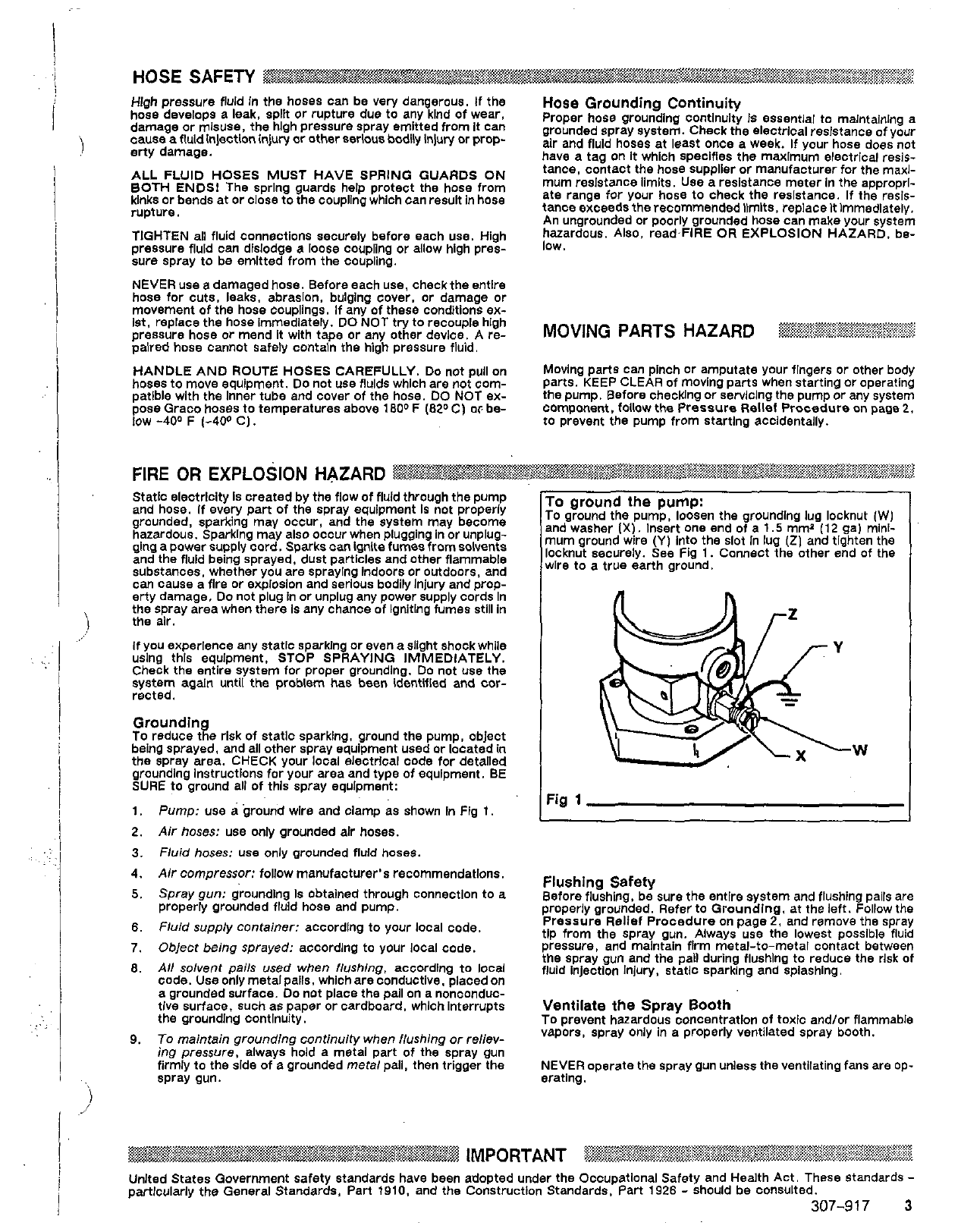
;I
'0
ground the pump:
'0
ground the pump, loosen the groundlng lug locknut
(W)
md washer
(X).
Insert one end of a
1.5
mmz
(12
gal mini-
ium ground wire
(Y)
Into the slot In lug
(21
and tighten the
lcknut securely. See Fig
1.
Connect the other end of the
/Ire to a true earth ground.
W
'ig
1
Before flushing, be sure the entlre system and flushing pails are
Flushing Safety
properly grounded. Refer to Groundlng, at the left. Follow the
Pressure Rellef Procedure on page
2,
and remove the spray
tip from the Spray gun. Always use the lowest possible fluid
pressure. and malntaln flrm metal-to-metal contact between
the spray gun and the pall during flushlng to reduce the rlsk of
fluid Injection Injury, statlc sparking and splashing.
Ventilate the Spray Booth
TO prevent hazardous concentratlon of toxic andlor flammable
vapors, spray Only
In
a properly ventilated spray booth.
NEVER
operate the spray gun unless the ventilating fans are op-
erating.


 Series User manual")