Grand Banks GB-36-127 User manual

OPERATIONS MANUAL
Welcome aboard
Kaizen
改善
GB-36-127
Owners: Michael Barrett and Holly Marold
425-750-1583
Specifications:

2
Hull ID WIDLC36-353 1973
VHF Call Number WdA9944
LOA 36’4”
Beam 12’ 2”
Draft 3’11”
Mast Height 18’4 From Waterline
Displacement 28,000 LBS
Fuel Capacity 400 Gallons in two tanks
Navigation Range (Approx) 1000 Miles
Water Capacity 240 Gallons in two tanks
Engine and Transmission Oil Chevron Delo 400 30W
Amp hours/House Batteries- Full Charge 400 Amp hours
TABLE OF CONTENTS

3
GRAND BANKS 36 SPECIFICATIONS 2
WELCOMEABOARD! 5
SAFETY GUIDELINES 6
BEFORE EMBARKING: 6
CRUISING CHEKLISTS 7
•General Preparation Checklist 8
•Navigation Preparation Checklist 8
•Engine Preparation Checklist 9
STARTING ENGINES 10
GETTING UNDERWAY 11
APPROACH AND DOCKING
ATTHEDOCK 12
ENGINESHUTDOWN 13
FUELING 14
ELECTRICAL SYSTEM 15
SHORE POWER (110 VOLT) 15
ELECTRICAL EFFICIENCIES: Helpful Hints 16
ELECTRICAL SYSTEM (D.C. Panel) 17-18
LINK 1000 19
A.C. PANEL AND INVERTER 20
ELECTRONICS 21-24
WATER SYSTEM 25
SANITATION & WASTE 26
SHOWER and DRAIN 26

4
PROPANE STOVE/OVEN 27
CRABBING and FISHING 28
CRABCOOKING 29
CABIN HEAT 30
STEREO SPEAKERS 30
TV/DVD PLAYER 31
BARBECUE 31
CANVAS and BIMINI 32
ANCHOR and WINDLASS 32
ANCHORAGE 32
LOWERING the ANCHOR 33
RAISING the ANCHOR 34
MOORINGCANS 35
DINGYS 36-37
THROUGH-HULL LOCATIONS 38
WHERE IS IT? 39
HOWDOI? 40
NAUTICALLIBRARY 41
Welcome aboard!

5
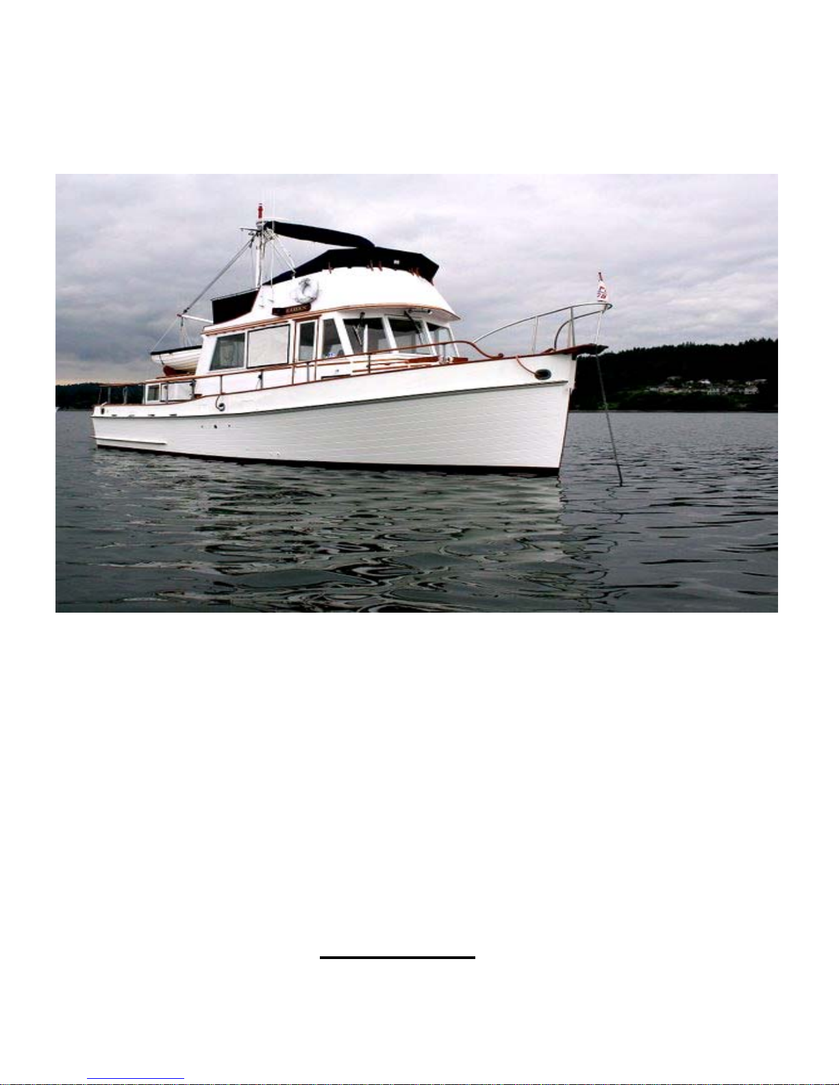
We are happy you have chosen “Kaizen“for your vacation. We are sure you will enjoy
cruising the lovely islands of the Pacific Northwest.
Kaizen was originally built in 1969, completely refurbished in 1993, and again from 2003-
2007.
Kaizen (改善)
Japanese for "change for the better" or "improvement"; the English translation is "continuous
improvement".
We hope you will enjoy the many extra amenities that have been added to make Kaizen
a comfortable cruiser.
•Upgraded decor, including oriental rugs, upholstery, miniblinds, and refrigeration. She
has a refurbished bridge including seats and canvas.
•Upgraded electrical system: 1000 watt Heart Inverter has been added, coupled with six
deep cycle golf cart batteries provides ample load capacity and ease of use. This
superior arrangement allows you to run small AC (110 volt) systems “on demand” in
peace and quiet. Chart plotter, TV & VCR, microwave, and coffee pot all work well (one
at a time).
•For cooking using the propane stove and the Magma propane grill doubles as a single
burner stove as well.
•Updated electronics package, July 2007
•Upgraded stereo sound system: Bose weather-resistant speakers in the Main Salon
and bridge accompany the stereo CD player and AM/FM radio.
•Kaizen is also equipped with a 9 foot Ranger rowing dinghy, and, the Avon ridged
inflatable dingy. A 3 hp outboard is also available, or you can row if you prefer.
•There is an Espar diesel heater with a thermostat mounted at the lower pilot’s station
for those cool summer mornings and to extend the chartering season.
Other features of “Kaizen” have been designed to enhance your overall enjoyment of
this special yacht, such as:
•Nautical Library: for your safety and reading enjoyment, you will appreciate the
comprehensive collection of reference literature and guidebooks, charts, instructional
videos, repair & maintenance manuals, etc.
Kaizen is well equipped to provide many of the comforts of home, while you explore the
spectacular cruising waters of the Great Northwest. Enjoy!
We hope this manual will help you become familiar with the Kaizen If you have questions
about the boat or about places to visit, please do not hesitate to ask the AYC staff.
SAFETY GUIDELINES

6
Kaizen is equipped with safety as a priority. Buy a safe and enjoyable charter can only
happen when the yacht and the skipper both function properly. The following information is
intended to assist you in the proper operation of the boats systems and to note some of the
most important safety precautions. A thorough understanding of the equipment and
procedures is your best assurance of having the best possible charter experience. Some
pointers:
•Familiarize yourself with boat systems – complete manuals are organized in binders,
located beneath the starboard seat, main salon.
•Familiarize yourself with the charts you will depend upon. Use the charts to keep track
of your position at all times – stay clear of rocks, shoals, old pilings, and kelp beds.
•Be on constant watch for logs and debris while underway – it is recommended that
lines of floating debris be crossed very slowly to avoid propeller and drive shaft
damage.
•Know the status of tides, currents, and weather forecasts. Conditions change fast!
•Do not cruise after dark or in low visibility conditions.
•All members of the crew should be familiar with the VHF Radio operation -
emergencies are no time to learn.
•Keep hands away from anchor windlass when operating.
BEFORE EMBARKING
1. Locate life jackets (May West type under bridge controls in large locker, and jacket
type in the aft hanging locker) and wear as necessary.
2. Review emergency procedures
3. Secure loose objects on deck and below.
CRUSING CHECKLIST

7
Bilge Main bilge access. In Grand Banks trawlers, bilge water tends
forward, so water level in the bilge is checked here.
Anchor Ready for use. Electric Windlass is controlled by remote switching
device.
Fresh Water Tanks Full. Capacity gauge is located in the aft head
Dockside Power Circuit breaker off. Power cord detached and secured.
Battery Power Circuit breaker set on “ALL” Position
Rowing Dingy Covered, Oars Secured
Inflatable Secured on stern with oars in place. Outboard secured to bracket
on bridge.
Mast Boom Down tight and secured
Decks Cleared
Galley and Heads Countertops cleared
Stove Countertop In Down position
Fenders On board and secured (once underway).
Lines On board and secured (once underway).
GENERAL PREPARATION CHECKLIST
Oil Level Dipstick on inboard side of each main engine

8
•DO NOT OVERFILL
•DO NOT OPERATE BELOW “ADD” MARK
Transmission
Fluid Level Dipsticks on inboard side of each transmission,
Remover, Wipe Dry and re-install dipstick
•DO NOT OVERFILL
•DO NOT OPERATE BELOW “ADD” MARK
•Should be checked immediately after operation. Check at
beginning of charter, once mid-way, and at completion of
charter.
Racor Fuel Filters Check for water or dirt in bowl. Drain into empty oil container or
bucket if needed. Container of clean diesel fuel can be used to
clean bowl. If bad fuel necessitates changing of filters, spares
located in spare part box (to port of engine room).
Fresh Water Coolant Check levels in expansion tanks. (Top of each Engine).
Cooling Water Valves should be open (handles upward parallel to valve).
Thru-hull Valves To check sea strainers, first close thru-hull valve. Do not over-
tighten sea strainer, as brass bolts can slip easily. Open thru-hull
valve when done, and check for leakage.
DO NOT OPEN UNLESS OBSTRUCTED OR NEEDS CLEANING.
Bilge Pumps Two automatic bilge pumps, fore under fwd ladder and aft under
floor of engine room vicinity of sea strainer, keep the bilges dry as
necessary. Test by switching from automatic to manual mode then
return to automatic setting – pump manually until flow stops – look
on STBD side.
(On/Off switches located portside of lower helm station).
ALWAYS LEAVE IN AUTO POSITION!
NAVIGATION PREPARATION CHECKLIST
Weather Forecast reviewed

9
Currents and Tides Reviewed
Cruise Plan and Charts At helm
Binoculars At helm
VHF Radios Power turned on with toggle switch on instrument panel on; set to
Channel 16
Chartplotters Power to all turned units on with toggle switch on the instrument
panel
Turn on Bridge Chartplotter first. It is the master.
DO NOT CHANGE THE MASTER
Depth Gages Displayed on Chartplotter both Helms
Radar Turned on (if needed) displayed on Chartplotter
Engine Preparation Checklist
1. Do daily check first (Remember your “WOBBS” every morning: Water
(Coolant), Oil, Bilges (Inspect and Pump-out), Belts and Sea Strainer.
2. Engines should be started with the Battery Switch in the ALL position. This is the
correct switch setting underway and when charging using the inverter when AC
3. Shore Power is on.
STARTING ENGINES
1. When on shore power, turn on the engine block heaters for about 3 hours prior to
starting.

10
2. DC Panel: Run exhaust fan for at least 60 seconds. REMEMBER TO TURN OFF.
3. Lower helm: Ensure both engine cut-off plungers are in the down position.
Ensure that the engine transmission controls (black knob handles) are in neutral
position (straight up and down).
4. Begin with the Port (left) Engine. For the first start of the day, use cold start procedure,
i.e., pull up cold start plunger and hold it as you advance the throttle all the way
forward, depress plunger, return throttle to idle position, then set engine throttle to
approximately one third (about 1000 RPM), set engine switch to “ON” position, alarm
will sound, press and hold start button until engine starts or for a maximum of ten
seconds. Engine should start immediately. Return throttle to idle position. If engine
does not start, repeat this step. If engine still does not start after repeated
attempts, GET PROFESSIONAL HELP.
5. Check for oil pressure (gauge), and check for cooling water flowing out (beneath swim
step)
6. If low oil pressure, or no cooling water, or if engine alarms continue to sound, shut
down immediately and correct the problem.
7. Repeat steps #3- #5 above, for starboard (right) engine.
8. IMPORTANT: Engine temperature should exceed 150 degrees before
accelerating beyond 1500 RPM.
9. NOTE: Engines can be restarted at the upper helm in an emergency as long as the
engine switches are in the ON position. Start buttons are located to the starboard of
depth gauge plunger/switch. To port of this plunger is the ship’s horn button. (Horn
circuit breaker on DC panel must be ON for the Horn to work).
GETTING UNDERWAY
1. Shore power switch to off. Remove shore power. Please instruct your crew in this
procedure. Not every one is aware of the locking tangs, power breakers at dockside,

11
or the bezel ring attachment on the fittings. Store the power cords on the bridge.
Refer to the A.C. section below.
2. While still at dock and idling (approximately 700 RPM), shift gears to test response
while tied to dock. Shift gears ONLY with throttle in idle. Pause in neutral when shifting
to forward or reverse.
3. Monitor engine instruments. A buzzer warning may sound for low oil pressure or high
temperatures, but your most reliable source to determine health of the engines is to
constantly monitor engine gauges. SHUT DOWN IF BUZZER SOUNDS WHILE
RUNNING. CHECK OIL PRESSURE & ENGINE TEMPERATURE.
4. Normal cruising RPM is 1800-1900, which will yield approximately 9 knots (10+ mph)
and 4 gph fuel consumption. The theoretical maximum RPM of 2200 might add 10%
increase in speed while also adding 50% increase in fuel consumption. NEVER
EXCEED 2400 RPM!
5. Note: knot meters read “speed through water” which includes the affect of currents and
tides, rather than true “speed over ground” (actual forward progress) as measured by
GPS. (Also, note the difference between the two should indicate the positive or
negative speed of current impacting the boat.)
6. Once again, watch out for logs and other floating debris, as well as crab pots and
fishing nets.
7. Check local wind and current and establish a maneuvering plan. Decide how to keep
clear of conflicting traffic. Direct the specific order or the removal of individual lines.
Recover the dock step and direct crew to walk or push the boat as appropriate.
8. Shift gears at idle RPM. A pause in neutral is appropriate.
9. Please do not remove lines or fenders until clear of the marina. Leaving them in place
will afford vital protection and options if circumstances go sour.
10.Once clear of the marina, store lines and fenders.
APPROACH AND DOCKING
During docking, use the FLYBRIDGE HELM for greater visibility to the stern. Have your
crew make ready the lines and fenders and give clear instructions on how you will be docking.

12
Often times your crew will need to step off from the swim step with the stern line. Another
crew member will need to be at the bow or mid-ships to hand over the next lines.
1. Check all gauges for proper reading and normal water volume at the exhaust.
2. Place dock lines on at all cleats, and fenders deployed on both sides (touching the
water, please) BEFORE YOU GO INTO THE MARINA.
3. Check local winds and currents.
4. Brief crew/line handlers on intentions, critical lines to be applied first.
5. “Kaizen” has a modest amount of momentum. Use neutral a lot, go easy, reverse, and
stop the boat if the dock is on the fenders. Continuing will only roll the fenders out of
the way and hull scratches will result. Do not allow your crew to jump off the gunwales.
Do not let them carry dock lines while they disembark. Both hands free for line
handlers until they get safely to the dock. Don’t force your crew to muscle the boat off
from a poor or fast approach. With as much weight as “Kaizen” displaces, injuries are
likely of desperation pushing is attempted. GO SLOW.
AT THE DOCK
1. Tie up the boat at least twice, once for nominal control then for position and security.
Check your line handlers’ cleatings. Reset fenders as appropriate.
2. If applying shore power, ensure that the boat end is installed first, turn the circuit
breaker off at the dock power box, and then plug it in. Turn the power back on and
verify good polarity and acceptance at the electrical panel by turning on the white main
master switch on the AC panel.
3. Secure unnecessary switches, turn on those circuit breakers necessary for the stay,
and ensure that the battery charger is on and operating properly.
4. Ensure that the inverter is charging.
ENGINE SHUT DOWN
1. Idle engines in neutral for at least five (5) minutes to cool down. By the time you finish
tying up or anchoring this time will have passed.

13
2. Stop engines one at a time, by lifting the engine cut-off plungers located between
controls, and turning the switch off after each engine has stopped. This will disengage
the alarm buzzers.
3. NOTE: DO NOT TURN THE IGNITION CIRCUIT BREAKERS OFF WHILE THE
ENGINE IS RUNNING AS YOU WILL LIKELY BURN OUT THE DIODES WHICH
ENABLE ALTERNATOR CHARGING CIRCIUTS.
4. Return cut-off plungers to down position.
FUELING
1. MAKE SURE YOU HAVE THE RIGHT FUEL! DIESEL! DIESEL! DIESEL! MAKE
SURE IT IS GOING INTO THE CORRECT DECK FILL!

14
2. DOUBLE-CHECK!
3. Use the DECK FITTING KEY which is kept under the step next to the entry door.
4. Ensure that you have the proper fill cap! Do not try to fill water and fuel at the same
time.
5. There are two 200 gallon fuel tanks with a total capacity of 400 gallons.
6. Place the DIESEL nozzle into the tank opening, pump slowly and evenly, and note the
sound of the fuel flow. Pumping too fast may not allow enough time for air to escape,
which may result in spouting from the tank opening. As the tank fills, the sound will rise
in pitch or gurgle.
7. Pay attention to the TANK OVERFLOW VENT on the outside of the hull near the tank
opening. The sound may indicate that the tank is nearly full. Disengage from any
conversation during this task.
8. Fill BOTH tanks when refueling. Top off carefully, and be prepared to catch spilled
fuel. Spillage may result in a nasty fine from law enforcement.
9. Re-screw the cap into the receiver. Do not over tighten; you only need to compress
the “O” ring adequately.
10.The tank levels can be monitored by observing the sight gauges in the engine room.
Valves located at tops and bottoms of gauges must be open a few turns to read. Then
close them.
11.Check the sight gauges in the engine room after fueling.
12.There are fuel crossover valves amidships at both tanks in the engine compartment.
The crossover valves are normally closed. Fuel supply should be set up for the
starboard (right) engine to draw fuel from the starboard tank and the port (left) engine
to draw from form the port tank.
ELECTRICAL SYSTEM SHORE POWER (110 VOLT)
1. AC power master switch (white knob) and breaker switches are located on main
electrical panel (to starboard on lower helm). TURN OFF MASTER BEFORE
CONNECTING SHORE POWER. Also turn off all AC panel switches and main breaker.

15
2. Power cord stows in the starboard side seat stowage on the bridge. Adapters stow in
the compartment under the entrance door.
3. Connect cord to boat first, then to shore power ensuring you use the correct adapter for
30 amp, 20 amp, or 15 amp service. Secure power cord at both ends to take strain off
connections.
4. After connecting to shore power, turn master switch to SHORE POWER position. Turn
on main circuit breaker. Check volt meter for reasonable (105-120 volts) levels. Turn
on desired 110v breakers. Check amp load to make sure you will not trip shore power
breaker.
5. BEFORE DISCONNECTING, SHUT OFF MASTER SWITCH ON MAIN CONTROL
PANEL.
Electrical Efficiencies: Helpful Hints
1. Be aware of your D.C. usage! The Link 1000 shows the house/inverter battery status.
This will help you to be more efficient approximately how many amps any given
appliance draws. This will help you learn to be more efficient with your electrical needs.

16
2. Plan your trip around expected charging needs. Of course, this is not an issue if you
plan to be connected to shore power. But if not, you will need to run the engines, run
the generator, or connect to shore power in order to recharge the batteries.
3. Battery charging options:
•Shore power (with inverter/charger breakers turned on). (BATT switch on ALL.)
•Run engines - cruising (each engine yields up to 65 amp hours with alternator).
(BATT switch on ALL.)
•Idle engines - while anchored or moored without shore power. 1000 RPM
(BATT switch on ALL.)
•(Note: Reserve Batteries are not negatively affected by usage of House
Batteries AS LONG AS BATTERY SWITCH IS SET TO POSITION #2.
Therefore, no matter how low your rate of discharge on your House Battery
bank, Kaizen’s engines should start).
4. Refrigerator: draws 5 -10 amps - typically, the largest consumer of amps (i.e., 12 hour
day x 5 -10 amps = 100 amp hour usage). To conserve, set to lowest satisfactory
temperature setting, and/or switch off at night. Control is located inside refer unit (in
back). With a fridge loaded with food, it may be more convenient to simply switch off
the refrigerator at the 12 volt panel. Refer/freezer should stay cold enough during the
night without power, acting as an ice box during the cooler nights. Also, keep
refrigerator full so there is less empty space requiring cooling.
5. Avoid unnecessary “guzzlers,” or at least be aware of their electrical draw. Examples:
Microwave – 10 amps (preferable to use for quick jobs rather than actual cooking).
Leaving lights on - (i.e., dinette light = 5 amps; 5 x 12 hours = 60 amp hours).
6. Turn off electronics when not in use.
7. Turn off inverter at remote panel when not using any AC (110 volt) systems. Note:
batteries will charge even when inverter is turned “off” when charging by generator or
main engines - cruising or idling.
By taking these simple precautions, you can enjoy the amenities and comforts of Kaizen’s
systems, while minimizing the need to charge of hook-up to shore power.
ELECTRICAL SYSTEM (D.C. Panel)
1. Be aware of your D.C. usage! The LINK 1000 battery monitor shows the
house/inverter battery status. This will help you to be more efficient with your electrical
needs. When the house battery voltage gets below 12.1 volts the batteries need
charging. There are three 200 amp hour batteries in the house/inverter bank for a total

17
of 600 amp hours. When the LINK 1000 shows a -200 amp hours it is time to charge
the batteries.
2. Both engines have high output externally regulated alternators that charge the
house/inverter batteries, the engine start batteries, and the windlass battery.
3. Plan your trip around expected charging needs. You will need to run the engines or
connect to shore power to keep the batteries charged.
4. Note that on the electrical diagram the start batteries are isolated from the
inverter/house batteries.
5. The helm D.C. battery switch should stay in the ALL position.
6. The inverter charges the house/inverter bank, the engine start batteries, and the
windless battery.
7. Turn off electronics and unnecessary items when not in use.
8. The bilge pump circuit breaker must remain on automatic.
9. Items marked on the electrical panel with a green dot can be left on as needed. Items
marked with a red dot must be off when not being used. Items marked with a blue dot
can be left on when leaving the boat.
10.The propane safety switch is wired to the cabin lights circuit breaker.
11.The port and starboard engine circuit breakers are used to energize the start circuits
for the respective engines. The push button switches are for starting. In the event that
there is insufficient charge in one of the batteries, more charge can be provided by
pressing the PARALLEL BATTERIES switch located above the D.C. panel. The switch
is “armed” by activating the Batteries Parallel switch in the engine room, right side of
the forward bulkhead. Both start circuit breakers must e on to accomplish this.

18
12.The engine and windlass batteries are all isolated from each other and the
inverter/house battery.
13.There is a volt meter in the engine room forward bulkhead that can monitor the start
batteries and the windlass battery.
•Starboard start battery is #1
•Port start battery is #2
•Windlass battery is #3
14.The starboard battery can be monitored by a volt meter on the port side of helm
station.
15.Never leave the engine room lights on as they use excessive amounts of power.
INK 1000 CONTROLLER
The Link 1000 is used to monitor the inverter/house battery status; (voltage, amp usage, amp
hours, and hours remaining on the battery) and to control charging and inverting. (The Link
1000 Owner’s Guide is on board)

19
1. The charge light over the pressure switch should be on and indicating green for the
charge system to be energized when shore power is available. If it is off and power is
available, press the CHARGE pressure switch and the green light should come on.
2. The inverter is on when the pressure switch is engaged and the green light over the
switch is on. If there is no shore power an A.C. power is required then the inverter
should be engaged and the green light over the INVERT pressure switch should be on.
3. The Link 1000 will also show the inverter/house battery status and should be the only
instrument to do so. There are other battery indicators but they measure different
things. Use the Link 1000 only for the inverter/house battery status. It will indicate
battery charging when the engine is running and battery discharge rates when there is
no external power source.
A.C. PANEL AND INVERTER
The A.C. circuit breakers located on the starboard side of the helm station are powered by
shore power or the inverter when shore poser is not available. The shore power A.C. main
switch and the inverter circuit breaker must be loft on at all times.

20
•The A.C. circuit breakers are for the A.C. outlets, the inverter input, the hot water
heater and the microwave.
•To supply power to the inverter for the charging, the inverter circuit breaker must be
on.
•The last three circuit breakers are for the shore power outlets and only have power
when A.C. shore power is on.
•When the inverter is inverting, on the inverter outlets are energized.
•Remember, the inverter is limited to 2000 watts continuous. The means that
the loads have to be limited to lest than 15 amps. Do not use the high A.C. loads
and a hair dryer at the same time. Do not use an electric heater or other large
appliances on the inverter outlets. The inverter is limited in what it can do so use it
with care.
•The LINK 1000 control panel at the left of the lower helm station controls the
inverter output and has LED indicator lights concerning the status of the inverter.
Refer the LINK 1000 manual.
•There is a shore power selector switch below the A.C. panel and it must be in the
shore power position at all times except when attaching/detaching the power cable.
•There is an A.C. voltmeter and ammeter just about the A.C. panel to monitor A.C.
usage.
•Turn off the inverter at remoter panel when using and A.C. (110 Volt) systems.
Note: batteries will charge even with the inverter is turned “off” when
charging by main engines, running at 1000 RPM or more.
Voltage (Wet Cell
Battery)
Battery
State
12.65 volts 100%
12.47 volts 75%
12.25 volts 50%
11.95 volts 25%
11.70 volts 0%
ELECTRONICS
RAYMARINE E SERIES HIGH PERFORMANCE MULTIFUNTION
NAVIGATION SYSTEM
(Manuals are located in maroon case)
This manual suits for next models
1
Table of contents
Other Grand Banks Boat manuals
Popular Boat manuals by other brands

PURSUIT
PURSUIT 2150 Walkaround owner's manual

Jet Thruster
Jet Thruster D-010-07 quick start

Yamaha
Yamaha WaveRunner VXS 2014 Owner's/operator's manual

Grady-White Boats
Grady-White Boats Freedom 275 owner's manual

Sevylor
Sevylor 1 Person Sit On Top Kayak (Non Covered) instructions

Bestway
Bestway BOLT X2 owner's manual