Grant Solar Pump Station Release note

0
C°
20
40
60 80 100
120
140
160
C°
0
20
40 60 80
100
120
UK | DOC 0096 | Rev 1.0 | October 2022
Grant
Solar Pump Station
Installation & Servicing Instructions

GRANT ENGINEERING (UK) LIMITED
Frankland Road, Blagrove Industrial Estate, Swindon, SN5 8YG
Tel: +44 (0)1380 736920 Fax: +44 (0)1380 736991
improvement. However, no responsibility of any kind for any injury, death, loss, damage or delay however caused resulting from the use of this manual can be accepted by Grant Engineering
(UK) Limited, the author or others involved in its publication.
© Grant Engineering (UK) Limited. No part of this manual may be reproduced by any means without prior written consent.
IMPORTANT NOTE FOR INSTALLERS
Please read these instructions in conjunction with the instructions
supplied with the Grant Sahara Solar Thermal System (Grant UK
After commissioning, please leave both the System Installation
Instructions and these Grant Solar Pump Station Instructions with
the user for future reference.
Important: All system pipe connections must use
compression ttings with brass olives. Soft soldered joints
must NOT be used on the solar primary circuit. Plastic pipe
must not be used for any part of the solar primary circuit.
SPECIAL TEXT FORMATS
The following special text formats are used in these instructions
for the purposes listed below:
! WARNING !
Warning of possible human injury as a consequence of not
following the instructions in the warning.
! NOTE !
Used for emphasis or information not directly concerned
with the surrounding text but of importance to the reader.
! CAUTION !
Caution concerning likely damage to equipment or tools
as a consequence of not following the instructions in the
caution.
SERVICING
The Grant Solar Pump Station Supplied with your Grant Solar
Thermal system should be inspected at least every twelve
months.

1 INTRODUCTION 4
1.1 General 4
2 TECHNICAL DATA 5
2.1 Grant Solar Pump Station
Technical Data 5
2.2 Pump Performance 6
2.3 Dimensions 7
3 INSTALLATION 9
3.1 General 9
3.2 Regulations and Standards 9
3.3 Location 9
3.4 Safety 9
3.5 Fitting Procedure 9
3.7 2-Port Valve 12
3.8 Expansion Vessel 12
3.9 Safety Valve Discharge 12
4 COMMISSIONING 16
4.1 Expansion Vessel 16
4.2 Filling Valves 16
4.3 Gravity Brakes 16
4.4 Solar Fluid 17
4.5 Filling the System 17
4.6 Filling Procedure 18
4.7 Releasing Trapped Air 19
4.8 Setting the Flow Rate 19
5 FAULT FINDING 20
5.2 Pump not Operating 20
5.3 Loss of System Pressure 20
6 SPARE PARTS 21
NOTES 22
Contents Page 3
CONTENTS

Section 1: IntroductionPage 4
1.1 GENERAL
systems.
All components are housed within an insulated enclosure designed to be wall mounted.
The Grant Solar Pump Station provides the following functions:
• System pressure and temperature readings
• Safety pressure relief valve and discharge connection
• System expansion vessel connection point
• Isolation valves for upper and lower system levels and pump
Flow - from Collectors
Return - to Collectors
0
C°
20
40
60 80 100
120
140
160
C°
0
20
40 60 80
100
120
Figure 1-1: The Grant Solar Pump Station with front cover removed (Grundfos Para pump shown)
1 INTRODUCTION

Section 2: Technical Data Page 5
2.1 GRANT SOLAR PUMP STATION TECHNICAL DATA
Table 2-1: Technical data
Specications for The Grant Solar Pump Station
Dimensions 440 x 280 x 150 (mm)
Weight without packaging 5.2 kg
Pump mounting length 130mm
97mm
Body material Brass
Temperature range of pump operation
Flow pump
Measuring range
System pipe connections
Safety valve lift pressure 6 bar
Safety valve discharge connection
Pressure gauge range 0-10 bar
Thermometer gauge range
50 %
Electrical supply 230-240V 50 Hz
Insulation EPP
Tightening elements EPDM
Flow and Return valves
Min pressure to open check valve
Medium Mixture of non-toxic polypropylene glycol, inhibitors, and dye
Solar controller
2 TECHNICAL DATA

2.2 PUMP PERFORMANCE
Section 2: Technical DataPage 6
Pumped liquid = Water
Liquid temperature during operation = 60°
Density = 983.2 Kg/m³
H
[m]
Q [m³/h]
UPM3 SOLAR
8.5
8.0
7.5
7.0
6.5
6.0
5.5
5.0
4.5
4.0
3.5
3.0
2.5
2.0
1.5
1.0
0.5
0.2 0.4 0.6 0.8 1.0 1.2 1.4 1.6 1.8 2.0 2.2 2.4 2.6 2.8 3.0 3.2 3.4
0
P1
[W]
45
40
35
30
25
20
15
10
5
0
Figure 2-1: Grundfos characteristics Q(H)
Figure 2-2: Grundfos energy consumption characteristics
2.2.1 GRUNDFOS UPM3 SOLAR 7.5M

L/min
12
10
4
2
8
6
97 111
240
413.45
L/min
³/4”³/4”
41
³/4”³/4”
³/4”³/4”
0
C°
20
40
60 80 100
120
140
160
C°
0
20
40 60 80
100
120
Figure 2-7: Front view of the Grant Solar Pump Station
150
50
420
Figure 2-6: Side view of the Grant Solar Pump
Station
62
30
Figure 2-8: Plan view of the Grant Solar Pump Station
Section 2: Technical Data Page 7
2.3 DIMENSIONS

Section 2: Technical Data Page 8
L/min
12
10
4
2
8
6
L/min
³/4”³/4”
15
14
13
12
11
10
9
8
7
6
5
4
3
2
1
17
16
18
19
0
C°
20
40
60 80 100
120
140
160
C°
0
20
40 60 80
100
120
Figure 2-9 of the Grant Solar Pump Station
2.4 COMPONENTS
Table 2-2:
Key No. Description
1
2 Safety valve (6bar)
3 Safety valve discharge connection
4 Pressure gauge (0-10bar)
5
6
7
8
9
10
11
12
13
14 Air separator with integral manual vent - ¾’’ x ¾’’ Male (External Thread)
15 Wall bracket
16 Insulated housing
17
18
19

Section 3: Installation Page 9
3.1 GENERAL
Installation of this pump station must be carried out by a
competent installer in compliance with all current local Building
Regulations, codes of practice, Health & Safety legislation and
any relevant bylaws and regulations in force at the time.
electrician. The electrical installation must comply with the
requirements of the Electricity at Work Regulations 1989 and
BS7671:2008 - IET Wiring Regulations 17th Edition British
Standards Institutions (including all amendments).
3.2 REGULATIONS AND STANDARDS
The installation of the Grant Solar Pump Station must be in
accordance with the following recommendations, as applicable:
• Building Regulations for England and Wales, and Building
Standards for Scotland
• Local Bylaws (check with the Local Authority for the area)
• Water Supply (Water Fittings) Regulations 1999
The installation should also be in accordance with the latest
• BS7671 and amendments
• BS EN 12831
3.3 LOCATION
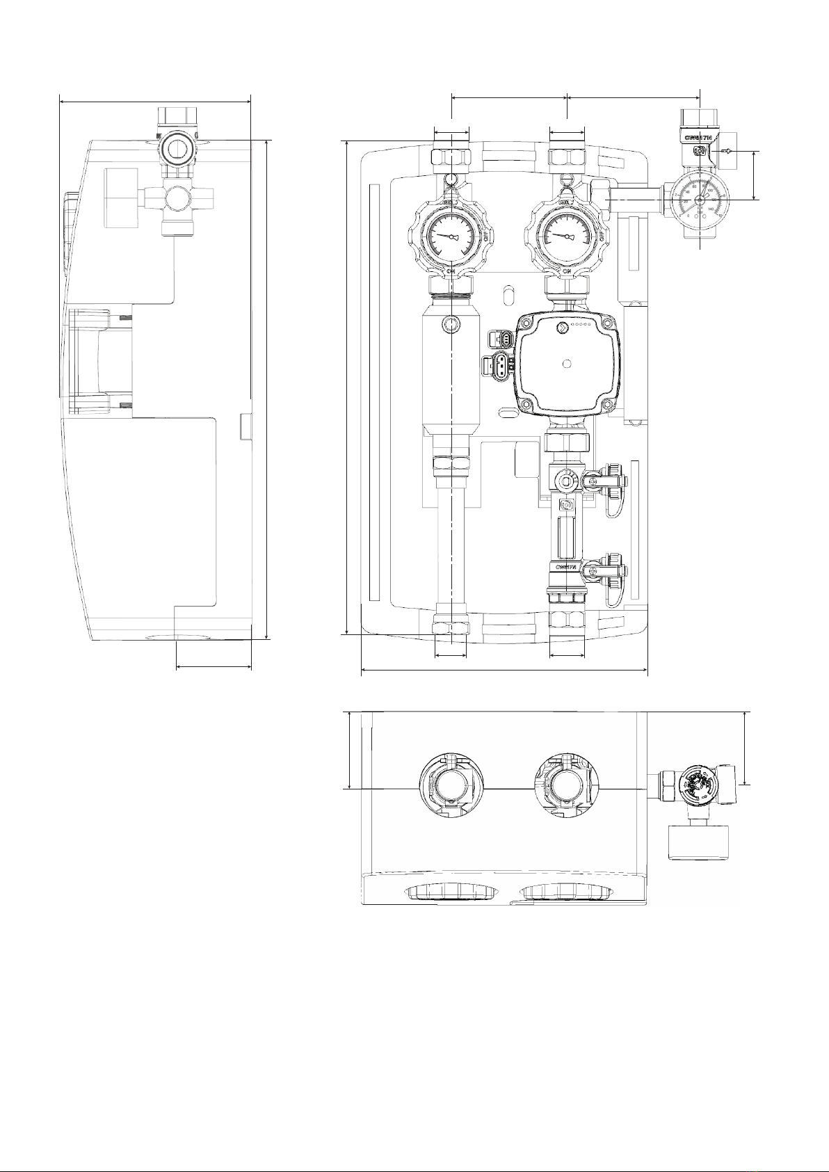
The Grant Solar Pump Station can be mounted on any suitable
wall surface capable of carrying the weight of the Grant Solar
Pump Station (refer to Table 2-1) where the required clearances
can be achieved. Leave at least 20 cm at each side of the Grant
Solar Pump Station.
Before mounting of the Grant Solar Pump Station an installation
damage to the elements of the Grant Solar Pump Station. The
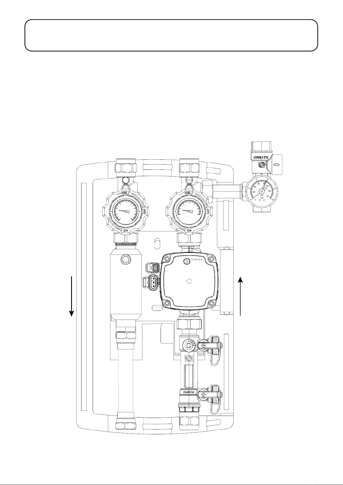
pump group is designed for wall mounting in an upright position.
The Grant Solar Pump Station MUST only be installed inside
a property, and not located externally, as it not designed to be
weatherproof.
3.4 SAFETY
The Grant Solar Pump Station is intended only for closed solar
installation. The Grant Solar Pump Station complies with the
current technical standards and technical safety regulations.
Each device is checked for proper operation and safety prior to
shipping.
The Grant Solar Pump Station MUST only be installed and
operated by trained personnel. Untrained personnel can work only
under the supervision of an experienced person, who is familiar
with the way the unit works. Before installation, the installer must
carefully read and understand these instructions.
! WARNING !
The temperature inside the Grant Solar Pump Station can
reach dangerous temperatures that can cause serious
burns.
! WARNING !
Ensure that the electrical supply has been isolated before
making any wiring connections.
3 INSTALLATION
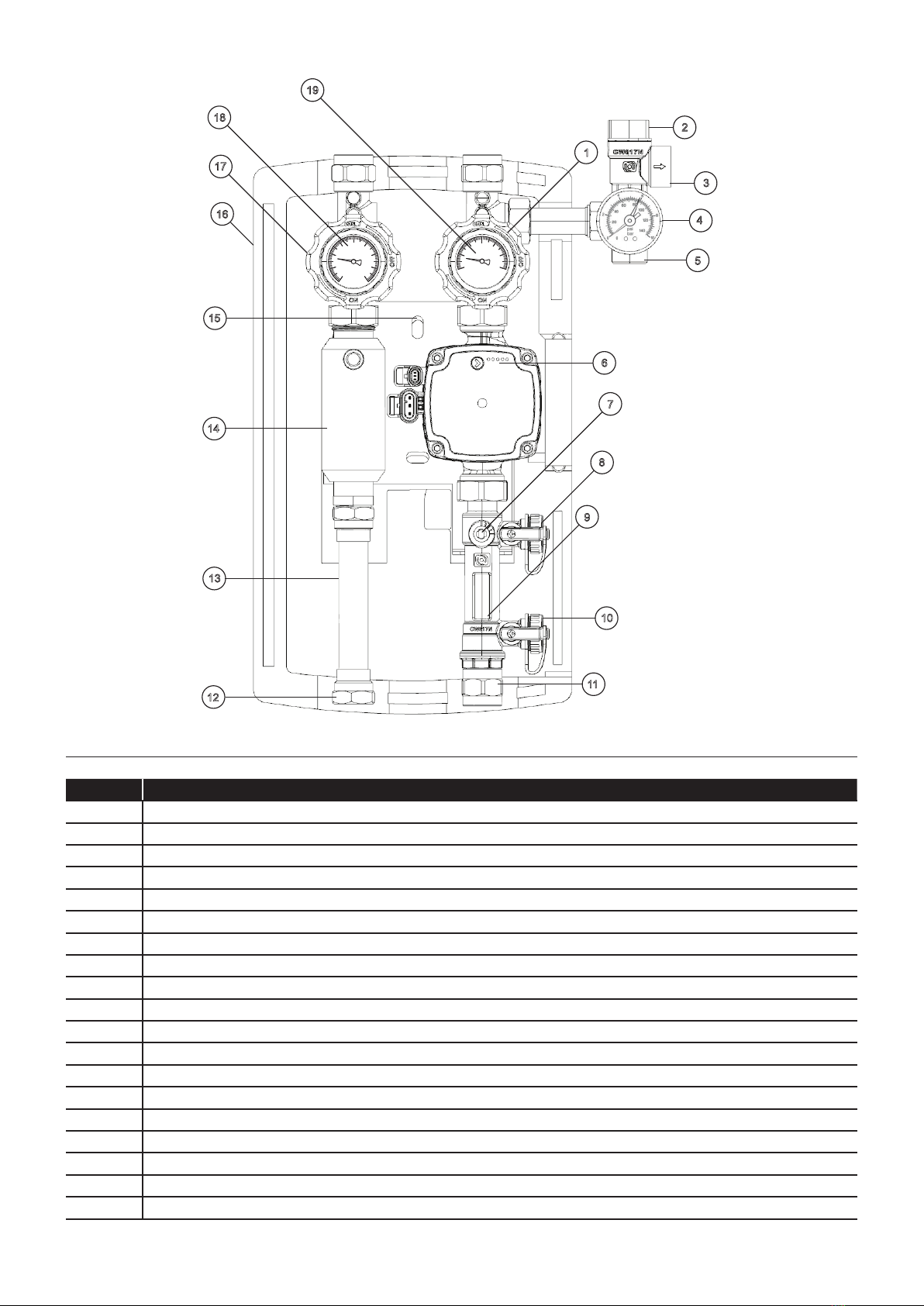
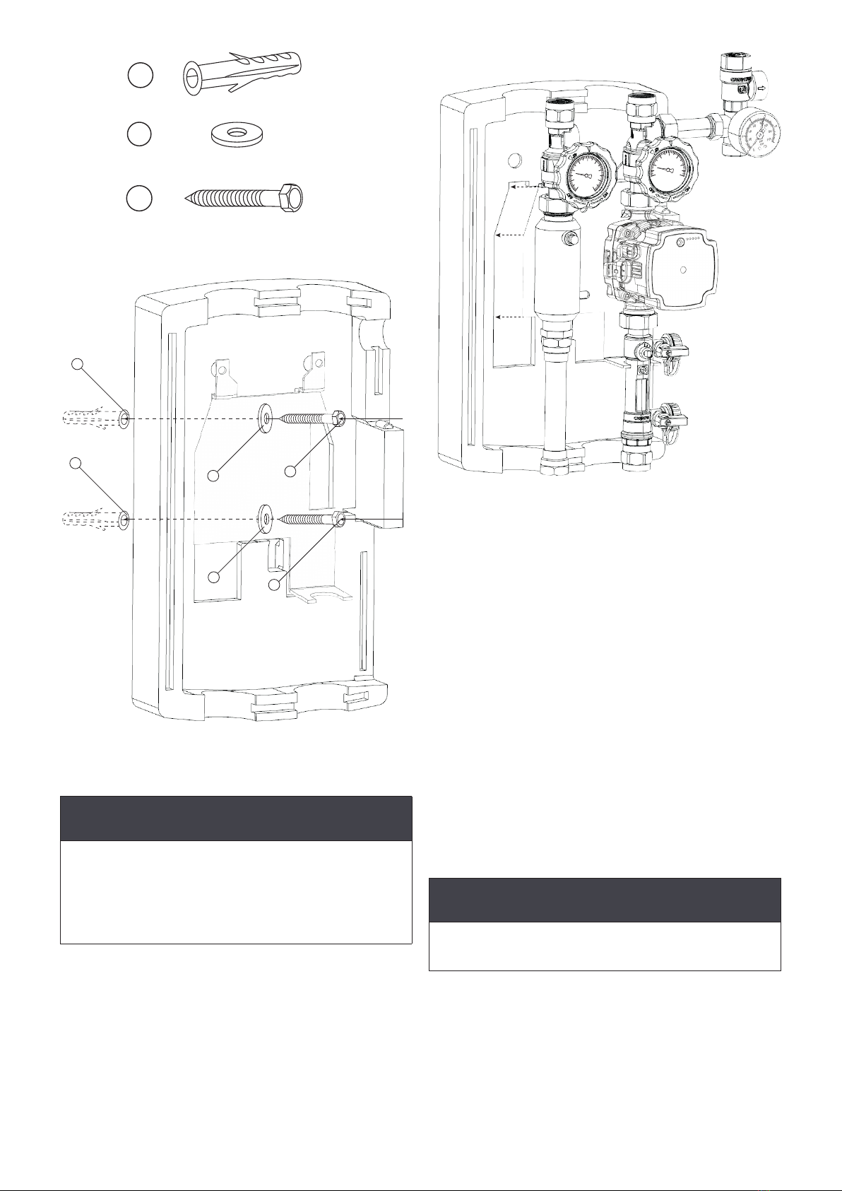
3.5 FITTING PROCEDURE
1. Refer to Figure 3-1. Take the two coach screws (3), the two
plugs (1) and the two metallic washers (2) from the wall
bracket kit
2. Remove the front section of the insulated pump station
housing
3.
4. Position the back section of the insulated housing in the
required location. If necessary check the cover is level using
a spirit level on the side and mark the top hole of the wall
bracket.
5.
set into the marked hole with a 10 mm drill bit.
6. Position the back section of the insulated housing in the
(3). Refer to Figure 3-2.
! CAUTION !
When xing the coach screw in step 6 proceed carefully.
The insulation is not rigid and overtightening the screw
could damage it.
7. Mark the position of the lower hole of the wall bracket on the
wall.
8. Remove the coach screw and carefully lift the back section of
the insulated housing
9.
pump set into the marked hole with a 10 mm drill bit
10. Fit
section of the insulated housing taking care to insert it
completely. Refer to Figure 3-3.
11. Lift the back section of the insulated housing and the wall
the two coach screws (3) and the two metallic washers (2).
Place the washers on the outside of the bracket mounting
holes, as shown in Figure 3-2.
! NOTE !
The Grant Solar Pump Station MUST only be installed
vertically, as shown in Figure 1-1.

3.6 FLOW AND RETURN CONNECTIONS
connection on the left and return connection on the right (viewed
from front). Refer to Figure 1-1.
follows:
1.
of the female connector of the copper pipe.
1.
2.
a seal.
3.
compression adaptor in the return connection. Tighten to
form a seal.
If more than one heating appliance is being connected to the
Grant Solar Pump Station, pipework connections between the
appliances should be made prior to making the connection to the
Grant Solar Pump Station.
Section 3: InstallationPage 10
10
0
C°
20
40
60
80
100
120
140
160
C°
0
20
40 60
80
100
120
Figure 3-3
bracket into the back section of the insulated housing
2
1
1
3
3
2
Figure 3-2
housing and the bracket into the wall
2x
2x
2x
1
2
3
Figure 3-1: Wall bracket kit items
! CAUTION !
During assembly, do not overtighten the threads. Some
leakage could result over time.
! CAUTION !
The Grant Solar Pump Station should be installed with
a minimum of 200mm clearance around the insulative
housing.
It MUST NOT be subjected to excessive temperatures, such
as those which occur during welding or soldering. The
Grant Solar Pump Station should be mounted after such
works required in the surrounding area are performed.

Section 3: Installation Page 11
! NOTE !
This is a diagrammatic view showing the connections to
the Grant Solar Pump Station. As such it does NOT include
all valves and controls and is NOT intended as a complete
system diagram.
Solar
Collectors
Hot Water Cylinder
Solar expansion
vessel
Safety (presure relief)
valve fluid recovery
container
0
C°
20
40
60 80 100
120
140
160
C°
0
20
40 60 80
100
120
Figure 3-4: System connections to solar pump station
! CAUTION !
All system pipe connections must use compression ttings
with brass olives. Soft soldered joints must NOT be used
on the solar primary circuit.
Plastic pipe must NOT be used for any part of the solar
primary circuit.

Section 3: InstallationPage 12
3.7 2-PORT VALVE
For Grant Sahara solar thermal installations using a Grant QR
! NOTE !
A high temperature rated motorised valve is only required
on installations where the solar thermal collectors are
installed below the level of the indirect solar coil contained
in the DHW cylinder.
If the Grant Sahara solar collector is installed above the indirect
solar coil, a high temperature motorised valve DOES NOT need to
instructions) for system diagrams and wiring schematics.
3.8 EXPANSION VESSEL
The correct size of expansion vessel should be used, based on
the volume of the system - i.e. the number of collectors, the length
and diameter of the system pipework, etc.
combined), an 18 litre expansion vessel is supplied as standard.
For 5 collectors a 24 litre expansion vessel is used. For larger
guidance on the expansion vessel required.
The expansion vessel is connected to the Grant Solar Pump
Station via the
with a
GS222074).
! NOTE !
This exible pipe cannot be cut and must be used as
supplied.
Mounting kit (Grant Part No. GS222073). This kit includes an
isolation valve union and the vessel mounting bracket.
Fix the mounting bracket to the wall, using the screws and wall
plugs provided, to position the vessel in the required location.
! NOTE !
The expansion vessel must be located BELOW the
connection on the Grant Solar Pump Station with the
vessel connection pointing upwards. Refer to Figure 3-4.
Figure 3-5:
• Fit the small black sealing washer onto the threaded
connection of the bleed valve.
• Screw the bleed valve into the threaded port in the side of the
valve union body and tighten.
• Remove the thin nut from the thread on the valve union.
• Fit the threaded connection on the expansion vessel up
through the hole in the mounting bracket and secure using
the thin nut.
•
expansion vessel connection.
• Tighten the union nut to ensure the valve union in the
required position.
Flexible stainless steel pipe
Bleed valve
Union nut
Thin nut
Pipe union nut
Isolation valve
Isolation valve
Indicators
Vessel mounting
bracket
Expansion
vessel
Figure 3-5: Expansion vessel connection
manifold and expansion vessel union valve, using the sealing
washers provided with the pipe.
Ensure that the expansion vessel isolation valve is OPEN - this is
indicated when the two indicators (on the square end of the valve)
system.
3.9 SAFETY VALVE DISCHARGE
It is recommended that the safety valve discharge should be
connected to a suitable discharge recovery tank, such as the
Grant safety valve liquid recovery container with drain valve
(Grant Part No. GS550001).
This discharge pipe should be 15mm copper.
! NOTE !
Plastic pipe should NOT be used.

Section 3: Installation Page 13
Table 3-1:
Feature Specication
Nominal supply voltage
Hz
Minimum supply voltage
performance)
Motor protection
The motor is protected by the
electronics in the control box
and requires no external motor
protection
Enclosure class IPX4D
Equipment class I (EN 60335-1)
Insulation class F (EN 60335-1)
Temperature class
temperature
High voltage protection
Maximum ambient temperature
Maximum media temperature
Minimum media temperature
ambient air).
Storage temperature
Maximum system pressure 1 MPa (10 bar)
Minimum inlet pressure
temperature
Drinking water approvals
W270
De-blocking device Manual de-blocking device. Access
from front side
De-blocking software
every 0.3 - 0.4 seconds with max.
torque
3 x 20 seconds (5 minutes
interval), all pumps are lubricated
with glycerine
Dry run ability - during operation
Expected lifetime
Minimum switching time power
Reaction time - power on With relay: < 2 seconds.
Reaction time - standby With relay: < 2 seconds.
Reaction time - speed change < 1 second
Inrush current
Maximum leakage current
Speed range 563 to 5991rpm (depending on the
variant)
Relative humidity Maximum 95 %, non-condensing
environment
Standby power consumption
Sleep mode power consumption 0.4 W
Surge robustness
RF emissions
Acoustic sound pressure level (LP)
Maximum altitude of installation 2000 m above sea level
Before start-up
Before you start-up the product:
•
starting the product.
• Make sure that the required minimum inlet pressure is
available at the pump inlet.
•
vented.
Starting up the product
Before you start the pump:
1. Mount the pump in the correct position.
2.
3.
4. Fill and vent the system (refer to Sections 4.6 and 4.7).
5.
the pump inlet.
6. Switch on the power supply.
7. If the pump is externally controlled, check if the external
controller sends a signal that controls the speed or that might
have stopped the pump.
8. If the pump is internally controlled, the pump starts with
! CAUTION !
Do not start the pump until the system has been lled with
liquid and vented.
! NOTE !
UPM3 pumps are self-venting and do not have to be vented
before start-up. Air inside the pump is transported by the
liquid into the system shortly after start-up.
3.10 ELECTRICAL CONNECTION
3.10.1 GRUNDFOS UPM3 PUMP
Connecting the pump
The pump requires a 230V 50Hz power supply from the Grant
a 3-pin plug supplied with the pump. Refer to the installation
information on the electrical control system wiring.
The pump can also be controlled using a PWM signal if the Solar
! WARNING !
The electrical supply must be isolated before making
the connections to the solar pump. After making the
connections ensure cover is tted to enclosure before
reconnecting the electrical supply.

Figure 3-6:
Figure 3-7: Switching on the power supply
Operating panel
green LED and four yellow LEDs.
The operating panel shows:
•
• Alarm status
AC D E FB
De-blocking screw
Figure 3-8: Operating panel
Table 3-2: Key to Figure 3-8
Pos. Description
A Push button
B LED 1
LED 2
D LED 3
E LED 4
F LED 5
Alarm status
If the pump has detected one or more alarms, LED 1 switches
from green to red and one of the other LED lights yellow. Refer to
Table 3-4.
If multiple alarms are active at the same time, the LEDs only show
given in Table 3-4. When there is no active alarm anymore, the
operating panel switches back to the operation mode.
Section 3: InstallationPage 14
Hint for installers
•
1 hour before a long-term stop.
•
thoroughly.

Figure 3-9:
Control modes and curves
control feature).
Overview of operating panel control modes
Grundfos UPM3 Solar pumps can be controlled with the button on
the operating panel.
The LEDs on the operating panel show the control mode selected.
Table 3-3: Setting Operating Status of the UPM3 pump
Control mode LED1
green
LED2
green
LED3
yellow
LED4
yellow
LED5
yellow
¹
²
¹ 1 Flash per second (No PWM signal connection)
Control mode explanation
Constant curve
The pump runs on a constant curve, which means that it runs at a
constant speed or power.
The duty point of the pump moves up or down on the selected
constant curve, depending on the heat demand in the system.
PWM input signal prole C (solar)
The pump runs on constant speed curves depending on the
current PWM value.
Speed increases when the PWM value increases. If PWM equals
0, the pump stops.
Fault indication on the operating panel
When an alarm is active, the LEDs indicate the alarm type as
If multiple alarms are active at the same time, the LEDs only show
sequence of the table.
Table 3-5:
Control mode Head (m)
5
6
7.5
5 to 7.5
Section 3: Installation Page 15
Figure 3-10:
Table 3-4: Fault indication on the operating panel
Operation panel
LED1 LED2 LED3 LED4 LED5 Indication Pump operation
Rotor is
blocked
Trying to start again every
1.33 seconds Wait or deblock the shaft
Supply
voltage too
low
Only warning, pump runs
Electrical
error
Pump is stopped because
of low supply voltage or
serious failure

Section 4: CommissioningPage 16
4.1 EXPANSION VESSEL
Ensure that the expansion vessel charge pressure is correct
for the system pressure (when cold) and that this, in turn,
corresponds to the height of the system. Refer to Table 4-1.
The height of the system should be measured from the expansion
vessel to the top of the highest collector.
gas cushion to be equal to the formula:
Pgas cushion= (1.5 + 0.1*h)
! NOTE !
If the collectors are positioned below the level of the
expansion vessel (e.g. if the collectors are mounted
at ground level), then measure from the bottom of the
collectors to the expansion vessel. This will be a ‘negative’
height value, e.g. -5 metres. The vessel charge pressure
must be checked BEFORE lling the system.
4.2 FILLING VALVES
to Figure 4-1.
the Filling return valve.
Table 4-1: Expansion vessel pressures
Height dierence
(height of the
collector eld minus
height of expansion
vessel
Initial expansion
vessel charge
pressure (air charge
setting on valve)
System charge
pressure @20°C
(0.2 - 0.5 bar greater
than vessel charge
pressure)
- 5m ~ 1.0 bar ~ 1.3 bar
< 0m ~ 1.0 bar ~ 1.3 bar
< 5m ~ 1.5 bar ~ 1.8 bar
< 10m ~ 2.0 bar ~ 2.3 bar
< 15m ~ 2.5 bar ~ 2.8 bar
> 15m
guidance
Filling flow valve
L/min
12
10
4
2
8
6
Filling return valve
Filling/shut-off valve
FLOW DIRECTION
14
12
10
4
2
8
6
Figure 4-1:
Detail A
14
12
10
4
2
8
6
CLOSED BALL
VALVE
FILLING
EMPTYING
FILLING/FLUSHING
STATION HOSE
RETURNING HOSE OF
THE FILLING/FLUSHING
STATION
Figure 4-2:
the system
4.3 GRAVITY BRAKES
The gravity brakes (check valves) are incorporated into both the
at 20 mbar and are operated by turning the valve handle on the
valves as follows:
4.3.1 FLOW AND RETURN VALVES OPEN - ‘ON’
MARKERS ON THE UNDERSIDE OF THE
VALVE HANDLES IN HORIZONTAL
POSITION
be in the operation position (open), i.e. with ‘ON’ markers in
horizontal position. Refer to Figure 4-3.
4.3.2 GRAVITY BRAKES OPEN - ‘ON’
MARKERS OF THE VALVE HANDLES AT 45°
ANGLE CLOCKWISE
gravity brakes must be opened, i.e. by turning the valve handles
clockwise to an angle of 45°. Refer to Figure 4-4.
4.3.3 FLOW AND RETURN VALVES CLOSED -
‘OFF’ MARKERS ON THE UNDERSIDE
OF THE VALVE HANDLES IN
VERTICAL POSITION
handles 90° to the right (clockwise), i.e. until the 'OFF' markers
are horizontal. Refer to Figure 4-5.
4 COMMISSIONING

Section 4: Commissioning Page 17
°C °C
°C °C
0
C°
20
40
60 80 100
120
140
160
C°
0
20
40
60
80
100
120
Figure 4-3: Flow and return valves open
°C
°C
0
C°
20
40
60 80
100
120
140
160
C°
0
20
40 60
80
100
120
Figure 4-4: Gravity breaks open
°C
°C
0
C°
20
40
60
80
100
120
140
160
C°
0
20
40
60
80
100
120
Figure 4-5: Flow and return valves closed
4.5 FILLING THE SYSTEM
incorporating a high pressure pump, such as the Grant Solar
Filling Station. Refer to Figure 4-6.
! WARNING !
If the Grant Solar Pump Station is located in the roof space,
there must be a suitable at surface on which to stand the
lling station, e.g. oor, loft boarding or similar, capable of
carrying the weight of the lling station with a full tank of
solar uid.
Figure 4-6: Grant Solar Filling Station
4.4 SOLAR FLUID
In order to prevent frost and corrosion damage to the Grant Solar
the system.
If required, a copy of the Material Safety Data Sheet for the Grant

Section 4: CommissioningPage 18
Manual
Air Vent
Air
Separator
Figure 4-8: Air separator and air vent
4.6.1 PHASE 1
•
Filling Flow valve connection and open the valve. Refer to
Figure 4-2.
•
Return valve connection and open the valve. Refer to Figure
4-2.
•
•
system
•
position (to open the gravity brakes) as shown in Figure 4-4.
•
circuit for approx. 15 minutes
4.6.2 PHASE 2
•
valve and allow the system pressure to reach around 4 - 5
bar. If the pressure increases slowly, this tells us that the air
has remained in the solar system. Rapid opening the valve
Repeat until the pressure increases after the closing return
valve rapidly reaches the maximum pressure (4 - 5.5 bar)
• When the pressure reaches 5 bar, close the Filling Flow
•
free. After leaving the system at about 5 bar for a minimum
of 15 minutes, check if the pressure gauge shows any
•
discharged. This should be collected in a suitable container,
Figure 3-4 and Section 3.8).
! CAUTION !
Venting air from the system should only be carried out by
a competent installer. Frequent venting leads to system
pressure loss and disruption to the system operation.
4.6 FILLING PROCEDURE
Important: The collectors must be cool before lling the
system. They must be covered to stop solar radiation
reaching them, until the lling and commissioning procedure
is completed.
Before lling the system:
expansion vessel charge pressure. Refer to Table 4-1. At the time
should not be connected.
Figure 4-7:
4.6.3 PHASE 3
•
clockwise
• Switch on the circulating pump (by setting the solar controller
•
• Bleed the air separator using the manual air vent until the
• Set the operating pressure (as in Table 4-1) by carefully
4.6.4 PHASE 4
• Reset Flow and Return valves to fully open position. Refer to
Figure 4-3.
• Switch on the circulating pump (solar controller set to
•
4.8) by selecting the appropriate pump speed and by using
•
and screw the caps on both valves. Release the Filling
• Switch the solar controller to automatic operation and remove
covers from the collectors

Section 4: Commissioning Page 19
4.7 RELEASING TRAPPED AIR
separator and manually released via the air vent. There is no
need to use an automatic air vent elsewhere on the solar primary
circuit, e.g. at high level.
To release any air collected in the air separator, push a plastic
tube on the manual air vent outlet (Refer to Figure 4-8) and catch
anticlockwise until all air has been vented, i.e. a steady stream of
4.8 SETTING THE FLOW RATE
• Switch on the speed selector of the pump and set to 1st gear
the solar controller set the manual control of the solar pump
without the regulation of the rotation speed (100% the speed
of rotation of the solar pump)
• Using a screw driver or wrench turn the adjusting screw until
• The gear pump should be increased if you cannot achieve
details.
! NOTE !
For larger installations, please contact Grant Technical
Department for assistance.
! WARNING !
Danger of scalding!
The temperature of both the escaping air and the solar uid
can exceed 100°C.
Table 4-2:
Number of
solar panels
Type of
connection
Flow and
return pipe
diameter
Minimum
volume ow
rate
1 to 5 Up to 5 in series 15mm
6 2 x 3 in parallel 22mm
8 2 x 4 in parallel 22mm
9 3 x 3 in parallel 22mm
12 4 x 3 in parallel 22mm
Detail B
L/min
12
10
4
2
8
6
14
12
10
4
2
8
6
Figure 4-10: Flow rate indicator
Read flow rate from bottom edge of bobbin
L/min
12
10
4
2
8
6
14
12
10
4
2
8
6
Figure 4-9: Detail B - Flow rate indicator

Section 5: Fault Finding
Page 20
In the event of a problem occurring with your Grant Solar
Thermal System, follow the information given below in order
to identify and rectify the matter:
5.1 NO SYSTEM CIRCULATION
• Pump is not operating (Refer to Section 5.2)
• If pump is noisy, there may be air in the system
• Pump may be air locked and needs venting. Let the pump
run, the pump vents itself over time.
• Valves are closed - ensure that Flow and Return valves are
open.
5.2 PUMP NOT OPERATING
• No electrical supply to pump
•
•
•
•
•
•
•
to cool down
•
radiation)
•
•
on pump motor (see Figure 3-8) and rotate motor using a
screwdriver
• Motor capacitor failed - replace capacitor or pump motor
5.3 LOSS OF SYSTEM PRESSURE (ON
PRESSURE GAUGE)
•
• Expansion vessel pre-charge, lost-check and re-charge
vessel as necessary
•
replace valve
5 FAULT FINDING
Table of contents
Other Grant Water Pump manuals
Popular Water Pump manuals by other brands

Renkforce
Renkforce 1034029 operating instructions

Davey
Davey CS Series Installation & operating instructions

PYD Electrobombas
PYD Electrobombas PCV Series Operating and maintenance manual

Westfalia
Westfalia 95 39 57 Original instructions

Danfoss
Danfoss APP 21 Service guide

Grundfos
Grundfos CRN-SF Series Installation and operating instructions

Graco
Graco Viscount High-Flo Plus 25E933 Instructions-parts list

Star
Star STL001 manual

Dwyer Instruments
Dwyer Instruments BCHP Series Installation and operating instructions

Gardena
Gardena 4000/4 operating instructions

WOERNER
WOERNER GFZ Translation of the original operation manual

Current Tools
Current Tools 292 Operating, Maintenance, Safety and Parts Manual