Page 7
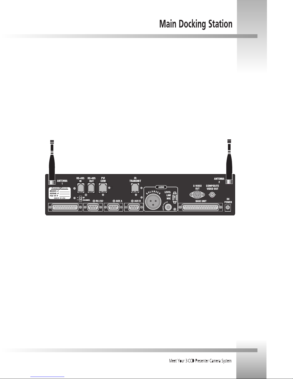
Now you can begin connecting your Main Docking Station to your CameraMan Camera System and your camera control devices.
RS-232 connection to PC
or other control device
PVI COM connection:
up to 250
Multi-conductor cable
connection: up to 10
PROTOCOL
configuration
switch
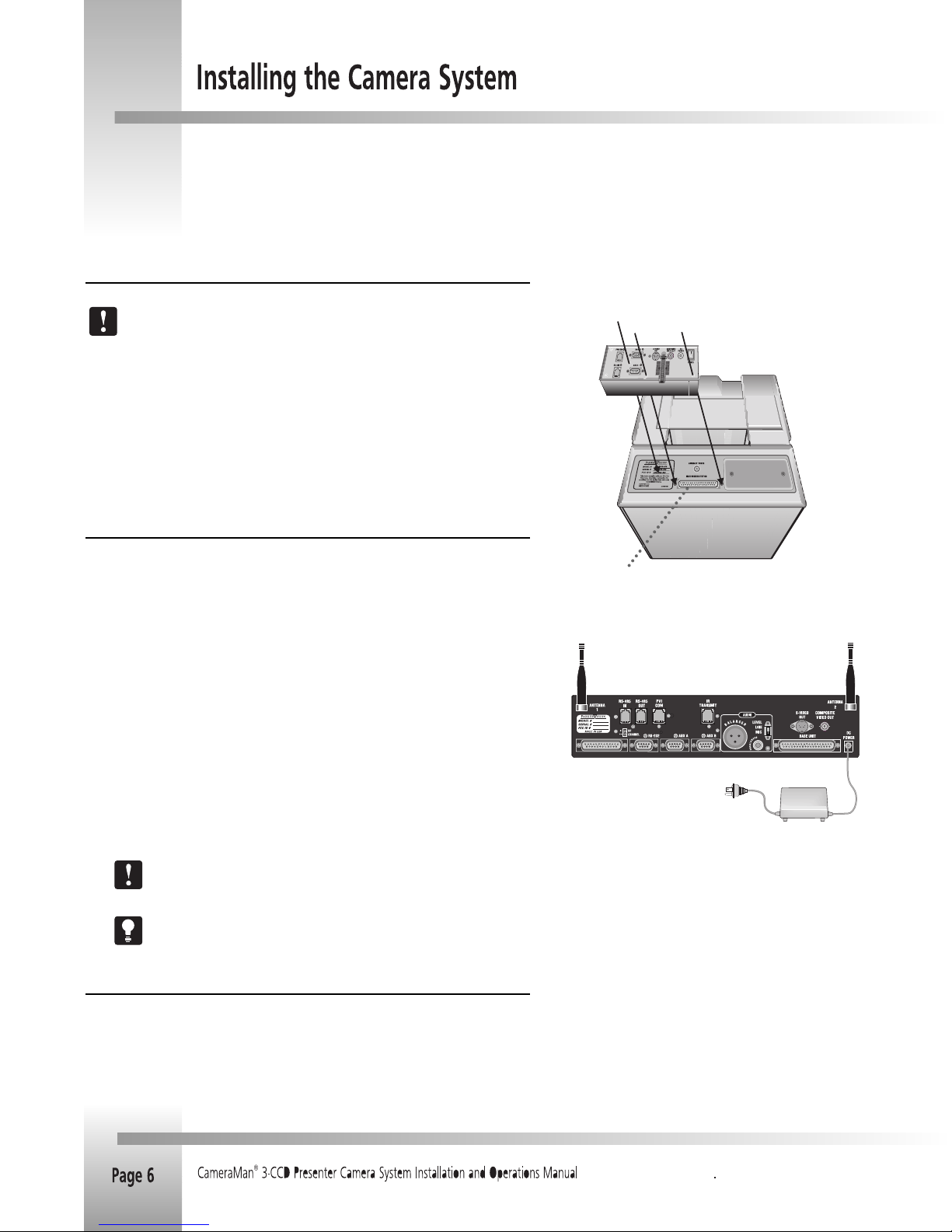
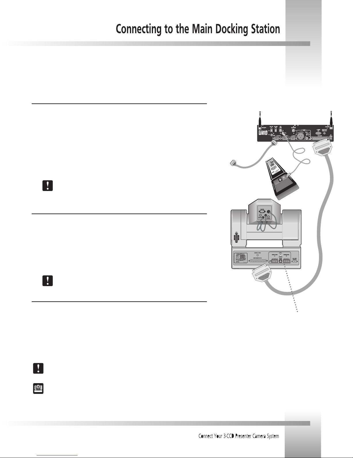
Connecting the CameraMan Cable
The autoTRACK camera connects to the Main Docking Station using the supplied CameraMan 10'
multi-conductor cable with DB-37 connectors on both ends.
1. Verify that the POWER switch is turned OFF on the front of the Main Docking Station
before making this connection.
2. Connect the DB-37 male connector to the back of the CameraMan camera and secure the
connection using the two connector screws located on the cable connector. This ensures
that the cable does not become dislodged due to the motion of the CameraMan camera.
3. Connect the other end of the CameraMan cable to the BASE UNIT connector on the back
of the Main Docking Station.
Verify that the CameraMan Cable is supported so that the camera does not drag the
cable as it moves. If the camera drags the cable, then system performance may be
compromised.
Connecting a Keypad/Controller
The Tracking System Keypad can be hard-wired to the Main Docking Station using a CameraMan
Keypad Cable (provided separately).
1. Connect one end of the cable to the RJ-11 type jack located in the battery compartment of
the keypad.
2. Connect the other end of the cable to the RJ-11 type jack on the back of the Main Docking
Station, labeled PVI COM.
3. The light on the keypad should illuminate momentarily, indicating that the keypad is ready.
Using cable other than supplied cable for the PVI COM port may cause damage. The
Tracking System Keypad can be hard-wired up to a maximum distance of 250.
Connecting to the RS-232 Port
The Presenter Camera System provides for RS-232 communications using the DB-9 jack on the back
of the Main Docking Station, labeled RS-232. This RS-232 port can be used to control the
CameraMan camera from external devices, such as a PC or other vendor control system (i.e., AMX or
Crestron). Connect to this port using a standard computer cable with a DB-9 connector. This port
operates at 9600 Baud (19,200 with CameraMan SHOT Director), No Parity, and software hand-
shaking using CameraMan High Reliability or Basic protocols (only High Reliability with SHOT
Director). The light located above the RS-232 port indicates communication activity.
Verify which protocol is being used by checking the PROTOCOL switch
(switch bank B- switch 1) on the back of the CameraMan camera.
For more information on setting the PROTOCOL on your CameraMan camera, see the
Installation and Operations Manual that came with the camera.