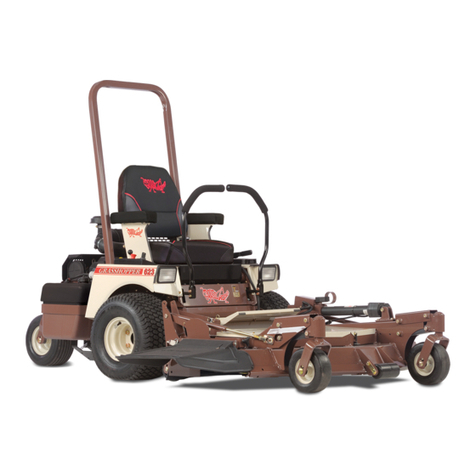
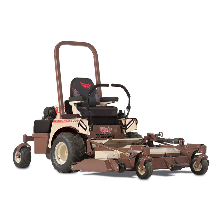
Grasshopper 718 Installation and operation manual

PRICE $7.00 Form 0590-172185
Printed in U.S.A.
II
I
I
I
THE GRASSHOPPER COMPANY
Moundridge, Kansas 67107 U.S.A.
PHONE (316) 345-8621
FAX (316) 345-2301
RIDING MOWER
MODEL 718
AND 718K
OPERATOR'S
MANUAL & PARTS LIST

Provide this information to your dealer to
obtain correct repair parts.
(Serial tag Is located under seat on trac-
tor frame by throHle.)
SERIAL NUMBER: _
MODEL:~ _
Use only genuine Grasshopper service
parts. Substitute parts will void the war-
ranty and may not meetstandards required
for safe and satisfactory operation. Record
the model and serial number of your
mower.
• Read the Instructions and warnings
carefully before using this machine.
• Read your Grasshopper warranty,
enclosed with tractor manual. To
validate warranty, fill In the required
Information and return the warranty
form to THE GRASSHOPPER CO.,
P.O. BOX 637, MOUNDRIDGE, KS
67107, within 10 days of purchase.
ATTENTION:
As with all lawn and grounds equipment, if
handled carelessly, it is a dangerous piece
of equipment. If Incorrectly used, this
machine can cause severe Injury. You,
the operator, are responsible wherfbperat-
ing it. Therefore, safety is of the utmost im-
portance.
The illustrations and data used in this man-
ual were current at the time of printing, but
due to possible in-line production changes,
your machine may vary slightly in detail.
The manufacturer reserves the right to
make changes or add improvements to its
products at any time without incurring any
obligation to make such changes to prod-
ucts manufactured previously.
The Grasshopper equipment you have pur-
chased has been carefully engineered and
manufactured to provide dependable and
satisfactory use. Like all mechanical prod-
ucts, it will require cleaning and upkeep.
Lubricate as specified in the manual. Ob-
serve all safety information in this manual
and safety decals on the tractor and attach-
ments.
We recommend that you carefully read this
entire manual before operating the unit.
Time spent in becoming fully acquainted
with its performance features, adjustments
and maintenance will add a longer and
more satisfactory life to your Grasshopper.
Congratulationson your selection of Grass-
hopper equipment. We believe you have
exercised excellent judgment in the pur-
chase of your Grasshopper. We are most
appreciative of your patronage.
INTRODUCTION

18
20
22
23
24
26
28
30
31
PARTS LIST AND ILLUSTRATION
Tractor Assembly - 718/718K
Drive Assembly
Drive Linkage
Reservoir
&
Hoses
PTO Shaft &Clutch Assembly
Wiring Diagram - 718
Wiring Diagram - 718K
Tall Wheel Options
Seat Assembly
11·14
ADJUSTMENTS AND TROUBLE SHOOTING
Gemini Transmission Trouble Shooting
Checking Gemini Transmission 011Level
Changing Gemini Transmission 011and Rlters
Neutral Adjustment
Gemini Transmission Removal
Engine Trouble Shooting
Engine Removal
Battery Service
Gemini Belt Replacement
Parking Brake Adjustment
Clutch/Brake Adjustment
Replacement of Clutch
7·10
OPERATION
Controls and Switches
Pre-Start Check List
Checking Gemini Transmission Oil Level
Changing Gemini Transmission Oil and Filters
Starting Engine
Steering Lever Operation
Uneven Terrain
Clutch/Brake Burnishing
Stopping Engine
6
LUBRICATION
&
SERVICE
Lubrication Chart
Capacities
Tire Air Pressure
Gemini Transmissions
Filters
4·5
SAFETY INFORMATION
Training
Preparation
Operational Safety
Maintenance Safety
Storing Safely
3
GENERAL INFORMATION
2
SAFETY DECALS
1
SPECIFICATIONS
PAGE
TABLE OF CONTENTS

1
Standard
Hour Meter
4.3 gals (16.3 liters)
Fuel Tank Capacity
46.5" (1.18M)
30.5" (.78M)
47" (1.19M)
73" (1.85M)
49.5" (1.23M)
700 Ibs.(317.5 Kg)
862 Ibs.(391 Kg)
Seat Back Height
Seat Cushion Height
Tractor Width
Tractor Length
Wheel Base
Weight - Uncrated
Weight - Crated
Dimensions of Tractor
20 x 10x 8 - 4 Ply Rated
13
x
5.0
x
6 Rib - 4 ply Rated
Front Drive Wheels
Tail Wheel
Tire Sizes
o
to 7 MPH (11.2 KM/H)
o
to 6 MPH (9.6 KM/H)
MPH Foward (variable)
MPH Reverse (variable)
Speed
- Dual levers independently control speed and direction of travel
- Zero turning radius (center of machine is pivot point)
Steering
Transmission - Gemini/Eaton Dual Path Hydrostatic Direct Drive
PTO rpm (max) - 3000
No-load rpm
Charging system
Electric starter
Electrical - safety interlocked
Electric clutch
422447
18h.p.
42.3 cu. in.
(694 cc)
3600
12VDC5 Amp
Mi8
18 h.p.
42.18 cu. in.
(691 cc)
3600
12VDC 15Amp
Model No.
H.P. - SAE Gross Intermittent H.P.
Cu. In.
Engine - 2 Cylinder 4 Cycle Air Cooled
718
Briggs
&
Stratton
718K
Kohler
SPECIFICATIONS

Part No. 165340
2
Part No. 165720
SHUT
OFf
ENGINE BEJORE REFUEUNG .
NEVER RU
RJa
11INK INDOORS OR
WHEN
ENGINE IS HOT.
WlP£ UP ALL SPlUED GASOUNE
BEFORESlMTlNG ENGINE .
00 NOT SMOKE
WHIlE
RERJBJNG . ""'"
A
CAUiIlON
Part No. 165631
...oPEJltATI!CONl"OL ~ &MOOTHI.
If
AND
SLOWlY, EBPECIALLVONSLOPES.
...UNIT MAV nOLL ON SLOPES WHEN
NOT UNDER POWER. ALWAYS SET
PA"K BRAkP.IMM£tMA'ELV WHeN
eNQINE
IS lURNEDOF' OR POW!;"
LOSS OCCURS,
... MDVI VERY SLOWLY
wtfl!N
ATTACIIMENTISREUOV&D.
...DQlfOTOPI!AATEON8TEr;:PSlOPP.S,
SEE OP£RA,lOA's MAHiJAL f"OA
DETAILS
-n
WARNING
.. ""'.. .......•
-~
DO NOT ALTER ELECTRICAL SYSTEM.
WRONG WIRI .NG CONNECTIONS WIll DAMAGE
ElECTRICAL COMPONENTS AND M AY MAKE
THE SAFETY SWITCHES INOPERATIVE...,..
Part No. 165345
0.--...,
Part No. 165021
TO AVOID
SERIOUS INJURY,
*
~~~~t~;N~A::~t[g~E ~~~
1------+-.....
SAFE TYAND OPERATING IN·
STRUCTIONS.
• KEEP FEET FORWARD ON
FOOl REST TO AVOID HEFl
PINCHING.
• BEFORE DISMOUNTING,STOP
ENGINE ANI) REMOVE KEY.
*
AllOW NO RIDERS.
*
AVOID OPERATING NEAR
DROP·OFFS, EMBANKMENTS
AND HOLES.
A
CAUTION
SAFETY DECALS
Replace Immediately If Damaged
A
WARNING Denotes a specific potential hazard.
A
CAUTION Is used for general reminders of good safety practices or to direct at-
tention to unsafe practices.
Throughout this manual, the term IMPORTANT is used to indicate that failure to observe can
cause damage to equipment. The terms CAUTION, WARNING, and DANGER are used in
conjunction with the Safety Alert Symbol, (a triangle with an exclamation mark), to indicate
the degree of hazard for items of personal safety.
This Safety Alert Symbol means ATTENTION! BECOME ALERT! YOUR SAFETY IS IN·
VOLVED!

3
Throughout this manual, references are
madeto right and left directions. These are
determined by standing at the rear of the
equipment and facing the direction of for-
ward travel. Mower blade rotation is clock-
wise as viewed from the top of mower.
A
WARNING
Some Illustrations in
this manual show the
tractor with safety
shields removedto pro-
vide a better view. The
mower should never be
operatedwith anysafety
shielding removed.
The illustrations and data used in this man-
ual were current at the time of printing, but
due to possible in-line production changes,
your machine may vary slightly in detail.
GRASSHOPPER reserves the right to re-
design and change the machine as may be
necessary without notification.
These operating and maintenance instruc-
tions have been compiled from extensive
field experience and engineering data.
Some information may be general in nature
due to unknown and varying conditions.
However, through experience and these
instructions, you should be able to develop
operating procedures suitable to your par-
ticular situation.
The purpose of this manual is to assist the
operator in maintaining and operating
GRASSHOPPER tractors. Read it care-
fully. It furnishes information and instruc-
tions that will help you achieve years of
dependable performance.
GENERAL INFORMATION

4
• Read operation section of this manual
before attempting to operate this unit.
• Fenders serve as shields, do not oper-
ate without them.
• Keep bystanders away from equipment
while it is in operation.
• Keep children and pets a safe distance
away. Never direct discharge toward
anyone.
• Start engine from operator's seat after
disengaging tractor power takeoff and
placing steering levers into the neutral
swing-out postion.
• Keep hand and feet away from under
mower while engine is running. Stay
clear of all moving parts on tractor and
on all attachments.
• If your tractor is equipped with a RaPS
(Roll Over Protection Structure), you
must wear your seat belt.
• Protect against noise. Wear suitable
hearing protection devices to protect
against objectionable noise.
• Never allow anyone behind tractor or in
front of implements when operating.
• Do not operate in reverse unless abso-
lutely necessary and then only after
careful observation of the entire area
behind you.
OPERATIONAL SAFETY
• Ensure all safety decals are installed
and in good condition.
e
Use correct counterweights when cer-
tain attachments are installed. (see
specific accessory installation instruc-
tions)
• Inspect area to be cut and remove
stones, branches or other debris that
might be thrown, causing injury or dam-
age.
• Never permit any person other than the
operator to ride or board the tractor or
implements at any time.
• Operate only in daylight or good artificial
light.
• Always wear relatively tight and belted
clothing to avoid entanglement in mov-
ing parts. Wear sturdy, rough soled
work shoes. Never operate tractor or
implements in bare feet, sandals or
sneakers.
• Ensure attachments are properly
mounted, adjusted and in good operat-
ing condition.
• Make sure driveline spring-activated
locking collar slides freely and is seated
firmly in tractor PTa groove.
• Remove accumulated debris from at-
tachment and tractor to avoid fire haz-
ard.
• Ensure all safety shielding is in good
condition and properly installed.
• Ensure either the discharge shield or
complete vacuum attachment is in-
stalled.
PREPARATION
• Safety instructions are important!
READ THIS MANUAL AND ALL
SAFETY RULES.
• Know your controls and how to stop
tractor, engine, and attachments quickly
in an emergency.
• To avoid accident or injury, do not allow
anyone to operate this equipment with-
out proper instructions. Any person
who operates this equipment MUST be
instructed in and be capable of the safe
operation of the unit, its attachments,
and all controls.
• Do not allow children or unqualified per-
sons to operate equipment.
TRAINING
A
CAUTION The designed and
tested safety of this
equipment depends on
it being operated within
the limitations as ex-
plained in this manual.
Read manual before op-
erating.
WORK SAFELY - FOLLOW THESE RULES

5
• Never store equipment with gasoline in
the tank inside a building where fumes
may reach an open flame or spark. Al-
low engine to cool before storing in an
enclosure.
• Always provide adequate ventilation
when running engine indoors - exhaust
gases contain carbon monoxide, an
odorless and deadly poison.
• Remove attachments from tractor. Re-
move all accumulated debris from trac-
tor and attachments.
• Sand areas where paint is chipped and
repaint to prevent rust. Lubricate all lo-
cations to prevent moisture damage
during storage.
STORING SAFELY
• Disconnect battery ground cable (-) be-
fore performing maintenance or service
if starting engine could cause injury.
• Never work under equipment without
safety blocks.
• Keep engine free of grass, leaves or ex-
cess grease to reduce fire hazard and
minimize engine overheating.
• Do not change engine governor settings
or overspeed engine.
• Keep tractor and attachments in good
operating conditions and all safety de-
vices in place.
• Periodically tighten all bolts, nuts and
screws and check that all cotter pins are
properly installed to ensure equipment
is in a safe condition.
MAINTENANCE SAFETY
• Take all possible precautions when
leaving tractor unattended: disengage
PTO, lower attachment, place controls
in neutral, set parking brake, stop en-
gine and remove key from ignition.
• Move very slowly when attachment is
removed. Never carry passengers.
• If operator must dismount to make ad-
justments, engine must not be running.
• Do not move steering levers from for-
ward to reverse or reverse to forward
position rapidly. The sudden change
could cause loss of control and/or dam-
age to equipment.
• Do not operate on steep slopes.
• Do not stop, start or change directions
suddenly on slopes.
• Use extreme care and maintain mini-
mum ground speed when traveling or
operating on a hillside, or over rough
ground and when operating close to
ditches or fences.
• Reduce speed on slopes and sharp
turns to minimize tipping or loss of con-
trol. Be careful when changing direc-
tions on slopes.
• Stay alert for holes, rocks and roots in
the terrain and other hidden hazards.
Keep away from drop-offs.
• Stop mower or other attachment and
tractor immediately upon striking an ob-
struction. Turn engine off, inspect at-
tachment and tractor, and repair dam-
age before resuming operation.
• Disengage power to attachment and
stop engine, remove key and wait for all
movement to stop before dismounting,
making adjustments, removing grass
catcher or unclogging any attachments.
• Never transport attachments with PTO
running.
• Watch for traffic when operating near or
crossing roadways.
• This unit is not equipped for highway
use, especially when safety lighting and
marking is required. It is not a recrea-
tional vehicle.
• This unit is not equipped with a drawbar.
Do not pull loads.
• Handle fuel carefully, it is highly flam-
mable. Always use an approved con-
tainer. Never remove fuel cap or add
fuel while engine is running. Allow en-
gine to cool two minutes before refuel-
ing. Do not spill fuel on hot engine
parts.

6
CrankcaseandAir Filter
Refer to the Engine Owner's Manualfor the time table for changing or service.
GEMINITRANSMISSION
Gemini Transmission Fluid Change 1000 hours
Gemini Transmission Filter Change 300 to 500 hours
TIREAIRPRESSURE
Drive Tires 8 - 10 Ibs
Rear Tires 12- 15 Ibs
CAPACITIES
Fuel Tank 4.3 U.S. Gallons
Gemini Transmission Oil Reservoir 2 U.S.Gallons
lubricate Every lubricate Every
Part
8
80
Hours of Usage Hours of Usage
Rear wheel bearings Two fittings
Clutch power shaft Two fittings
Drive shaft Three fittings
For Geminitransmissions use Mobil DTE26
(Grasshopper Part No. 345280 for 1 gallon
container.) Forsevere duty, use Grasshop-
per Fluid Part No. 345050 (1 qt).
Use an SAE multi-purpose type grease for
all locations shown. Be sure to clean fitting
thoroughly before using grease gun.
The chart gives the frequency of lubrication
in operating hours based on normal opera-
tion conditions. Severe or unusual condi-
tions may require more frequent lubrication.
Do not let excess grease collect on or
around parts, particularly when operating in
sandy areas.
Be familiar with all safety practices on
pages 4 &5.
A
WARNING Lower attachment to
ground, shut off tractor
engine,removekey and
wires to spark plug be-
fore servicing.
A
CAUTION Always wear safety
glasses and ear pro-
tection when perform-
ing any service or
matn-
tenance function that
could cause injury to
eyesor ears.
LUBRICATION AND SERVICE

7
• Check tire pressure. Improper pres-
sure will adversely affect traction, steer-
ing and level cutting height (see page
6).
• Check that cooling fins on the Gemini
transmissions are clean.
r!'I'_'~®3;.
Donot
fill
fuel tankwhile
engine is running. Al-
low engine to cool two
minutes before refuel-
ing. Iffuel is spilled, do
not start engine and
avoid creating any
source of ignition until
the fuel hasevaporated.
• Check air cleaner (refer to Engine Op-
erator's Manual). When mowing dry,
dusty and long grass, it may be neces-
sary to remove and clean the air intake
on the air cleaner.
• Check to be sure engine is free of dirt
and debris.
• Check fuel level. Refer to Engine Man-
ual for correct fuel for your require-
ments.
A
WARNING Removespark plug wire
to prevent accidental
engine starting before
attempting to remove
grasswrap from PTO.
• Check for grass wrap on PTO shaft.
When mowing long grass, turn off key
and check for grass wrap around PTO
shaft every 30 minutes of operation.
IMPORTANT: When mowing dry,
dusty and long grass, it
may be necessary to
removeandcleanair in-
take frequently topre-
vent engine overheat-
ing.
• Place tractor on level surface.
• Check crankcase oil level (refer to En-
gine Operator's Manual for proper level
and type of oil used).
• Remove and clean air intake screen.
PRESTARTCHECKLIST
Several safety switches are incorporated in
the unit's design to prevent it from being
started out of neutral or with the PTO en-
gaged. All controls must be in the "OFF" or
neutral position before the unit can be
started. There is a safety switch under the
operator's seat that will cause the engine to
stop, should the operator leave the seat
with any control engaged.
Operating this unit is not difficult once you
master the use of the controls. We recom-
mend you equip the tractor with the attach-
ment you will be using and practice in a flat
open area at a medium throttle setting until
you are comfortable with the controls.
Stop tractor by moving steering control to
neutral. Stop engine by turning key to
"OFF" position. Disengage power to at-
tachments by moving PTO switch to "OFF"
(down) position.
Know your controls and how to stop trac-
tor, engine and attachments quickly in an
emergency.
CONTROLSANDSWITCHES
The safe operation of this machine is the
responsibility of the operator. The operator
should be familiar with the tractor and all
attachments that will be used before start-
ing operation. Refer to and read safety in-
formation on pages 4 &5.
OPERATION

I
I
I
~
I
f
!
I
!
I
I
I
!
I
8
You will enhance the starter life by using
short starting cycles of several seconds.
Engaging starter motor more than 15 sec-
onds per minute can result in damage to
starter.
• To start tractor, position yourself on the
tractor seat.
• Place both steering controls in swing-
out neutral position.
e
Place electric clutch switch in "OFF"
(down) position.
• Set the throttle at 1/3 open.
• Insert the key into the starter switch.
• Turn the key to "START". Choke as
necessary to start. When engine starts,
release key immediately. Pushchoke in
gradually until choke is in and engine is
running smoothly.
• Warm the engine up at medium speed
for several minutes.
e
Donotallowchildren
to approach thema-
chine while the en-
gine is running.
e
Do not operate the
machine around
open flames, i.e.
trashfires.
e
Do not operate the
enginewhenanodor
of gasoline Is pres-
ent or other explo-
siveconditionsexist.
r!'.l;1~®#j;.•
Never start the en-
gine In confined
rooms. Exhaust
gases contain car-
bon monoxide, an
odorless and deadly
poison.
STARTING THE ENGINE
To change oil, remove drain plug from bot-
tom of oil reservoir and allow reservoir to
drain completely. Replace plug and
tighten. The Gemini transmissions cannot
be individually drained. Refill the reservoir
with 2.5 gallons of oil of the type and viscos-
ity as prescribed in the above section. Run
engine and check for leaks. Stop engine
and check that oil level is between the two
marks on the dipstick.
Note: No air bleeding Is necessary, the
system is self bleeding.
Change Gemini filters, one on each trans-
mission, every 300-500 hours depending
on severity of use; 500 hours under normal
mowing conditions and 300 hours if using a
grasscatcher or if temperatures are above
100 degrees F.
CHANGING GEMINI TRANSMISSION OIL
AND FILTERS
Check oil level with the engine turned off.
Pull dipstick on left side of machine next to
air inlet screen. This is the oil reservoir for
both Gemini transmissions. If oil is re-
quired, add until level is between the two
marks on the dipstick. Use Mobil DTE26
(Grasshopper Part No. 345280 for 1 gallon
container). For severe duty, use Grasshop-
per Fluid Part No. 345050 (1 qt).
CHECKING GEMINI TRANSMISSION OIL
LEVEL

9
A
CAUTION Always removekey from
switch when leaving
unit unattended or when
not In use.
• Set the throttle at an idle. Allow engine
to idle for several minutes.
• Move starter switch to "OFF" and re-
move key.
• Never choke carburetor to stop engine.
STOPPINGTHEENGINE
Place tractor in neutral, start engine and
run at fast idle. Turn clutch switch on 30
seconds and off 30 seconds, five times at
half-throttle and repeat five times at full
throttle. The time interval allows the clutch
surface to cool.
IMPORTANT: A new clutch, or one that
has not been used for three months,
will require burnishing to dress drive
surfaces. The clutch could fall if you do
not accomplish the following proce-
dure.
CLUTCH/BRAKEBURNISHING
A
WARNING Do not operate on
steep slopes. Opera-
tion on a steep slope
could cause loss of con-
trol, tractor overturn and
personal Injury or death.
Slow down on sharp turns and slopes to
prevent tipping or loss of control.
Avoid sudden starts and stops when travel-
ing up or down hill. Never mow down, or
back up, steep hills.
Pass diagonally through sharp dips and
avoid sharp drops. Practice will improve
your skills in maneuvering rough terrain.
A
WARNING Be careful when operat-
Ing tractor and mower
on uneven ground.
UNEVEN TERRAIN
Use fresh winter grade fuel, it is better for
winter starting than left over summer grade
gasoline.
A warm battery has better starting capacity
than a cold one.
Set throttle half open.
Use proper oil grade for temperature ex-
pected. (See Engine Manual).
COLD WEATHER STARTING TIPS

GENTLE RIGHT
(/J
GENTLE LEFT
I'
'\
H
10
~-:J
SHARP RIGHT
REVERSE
IMPORTANT: If you become con-
fused during opera-
tion, releaseboth steer-
Ing levers; they will
automatically return to
the centered neutral
.position and the tractor
will stop.
At half throttle, move both steering levers
from swing-out neutral inward. Move both
steering levers forward. To turn right, ad-
vance left lever further forward than right
lever. To turn left, advance right lever fur-
ther forward than left lever.
If
you leave one
steering lever in neutral and advance the
other lever, the tractor will turn a complete
circle. Move the levers to the rear and
practice turning and maneuvering in re-
verse. Once you learn how the controls
operate, practice until you become profi-
cient and are comfortable with the unit be-
fore you commence operation of an attach-
ment.
SHARP LEFT
move.
Speed and direction are controlled with
steering levers. Pushing the levers forward
will move the tractor forward. Pulling levers
to the rear will move tractor in reverse. The
further forward or rearward the steering lev-
ers are moved, the faster the machine will
A
WARNING
e
Donotmovesteering
leversfrom forward
to reverseor reverse
to forward position
rapidly. The sudden
change could cause
loss of control or
damage to equlp-
ment.
., The Grasshopper is
very unstable with-
out an attachment.
Move very slowly
when attachment is
removed. Never
carry passengers.
STEERINGLEVEROPERATION

11
9. Test drive machine for straight line
travel with both levers full forward. If
travel is not in a straight line, raise the
steering leverstop on the sidethat isthe
fastest i.e.: if machine goes to the left,
raise the right steering stop to slow
down the right transmission until travel
is straight ahead.
8. Reinstall linkage rod in control arm. If
ball stud does not reinstall into control
arm without moving the control arm, ad-
just length of linkage rod until it does to
assure neutral adjustment will be main-
tained when linkage is reconnected.
7. Repeat procedure for other side trans-
mission.
NOTE: Pivot bolt roller Is mounted off
center and works as an eccentric when
the bolt Is turned. Use special wrench
enclosed with operators manual to ed-
just.
1. Block up under tractor frame so both
drive wheels are off the ground.
2. Make sure parking brake is released.
3. Remove linkage rod (item 34) from
transmission control arm (item 23).
4. Place steering levers in the neutral
swing-out position and start engine.
5. If either of the drive wheels turn, pro-
ceed with the following adjustment.
6. Loosen locking nut (item 26) and rotate
pivot bolt (item 25) until neutral is
achieved. Tighten locking nut.
NEUTRAL ADJUSTMENT
(Refer to III.on page 22)
If drive wheels travel forward or reverse
when the steering lever is in swing-out posi-
tion (neutral), adjustment is required.
NO POSITIVE NEUTRAL POSITION
Changefilters, one on each transmission,
every 300-500 hours depending on severity
of use; 500 hours under normal mowing
conditions and 300 hours if using a
grasscatcher or if temperatures are above
100 degrees F. To change oil, remove
drain plug from bottom of oil reservoir and
allow reservoir to drain completely. Re-
place plug and tighten. The transmissions
cannot be individually drained. Refill the
reservoir with 2.5 gallons of oil of the type
and viscosity as prescribed in the above
section. Run engine and check for leaks.
Stop engine and check that oil level is be-
tween the two marks on the dipstick.
Note: No air bleeding is necessary, the
system Is self bleeding.
CHANGING GEMINI TRANSMISSION OIL
AND FILTERS
Check oil level with the engine turned off.
Pull dipstick on left side of machine next to
air inlet screen. This is the oil reservoir for
both transmissions. If oil is required, add
until level is between the two marks on the
dipstick. Use Mobil DTE26 (Grasshopper
Part No. 345280 for 1 gallon container).
For severe duty, use Grasshopper Fluid
Part No. 345050 for 1 quart container.
CHECKING GEMINI TRANSMISSION OIL
LEVEL
Check the fluid level and make sure the
proper amount of fluid is in the reservoir.
The cooling fins and fan blades should be
clean and free of foreign matter.
Loss of Power in the Gemini Transmission
GEMINI TRANSMISSION
TROUBLESHOOTING
ADJUSTMENTS AND TROUBLESHOOTING

12
I
I
!
I
I
!
I!
I
I
t
• Check for voltage at the S terminal of
the key switch. If voltage is not present,
key switch is defective.
• If voltage is present at S terminal, check
for voltage on either side of starter fuse
on fuse panel. If voltage is not present,
check for broken wire from the starter
switch to the fuse, or checkfor defective
fuse.
• If voltage is present at fuse, check for
voltage at NO post of left steering
switch with the blue wire. If voltage is
not present, check for broken wire be-
tween the left steering switch and fuse.
With the key switch held in the "START"
position, perform the following test:
• Steering levers must be in swing-out
neutral.
• PTO switch must be in "OFF"position.
• Check starter fuse on fuse panel under-
neath seat.
• Check for voltage at the centerpost with
the black wire on the PTO switch. If no
voltage is present, the battery is defec-
tive or the connection at the battery is
not making contact.
• Ifvoltage is present, then checkfor volt-
age at the terminal with the blue wire.
(PTO switch must be in "OFF"position).
If no voltage is present, the PTO switch
is defective.
• If VOltageis present at the blue wire on
the PTO switch, check for voltage at the
B terminal on the key switch. If no volt-
age is present, check for broken wire
between the two switches. If voltage is
present, proceed to the next series of
tests.
Engine will not crank:
ENGINETROUBLESHOOTING
Important: Disassembly of any part of
the transmission will void the warranty.
Should warranty service be required, take
the machine to your authorized Grasshop-
per dealer.
Reverse procedure to reinstall Gemini
transmission. Apply Locktite 242 to the
threads of the seven
1/4"
center mount
bolts and torque to 125 inch/lbs.
To remove wheel hub assembly (item 5,
page 20), use a puller bar andtwo
3/8
x 2
11
4" grade 8 bolts and flat washers to pull hub
from axle. When reinstalling hub, torque
axle nut (item 7) to 150 ftllbs and install a
new cotter pin. If hole does not line up,
tighten nut until it does.
1. Place tractor on stands and remove
fender and drive wheel.
2. Remove belt shield (item 17, page 20.)
3. Push in on belt idler and remove drive
belt.
4. Disconnect steering linkage from con-
trol arm on transmission (item 23, page
22.)
5. Remove parking brake assembly and
mounting bracket (item 40 or 41).
6. Drain oil reservoir or use plastic plugs
to cap off oil hoses. Remove oil filter
and two oil hoses from transmission.
7. Remove eight bolts that mount trans-
mission to Gemini center mount. Sup-
port transmission and remove two bolts
from transmission final drive to frame
and lower the Gemini unit out of the
frame.
NOTE: Transmission removal proce-
dure is the same for both transmissions.
GEMINI TRANSMISSION REMOVAL

13
• Remove key from key switch.
• Remove belt shield (item 17).
• Push down on belt idler and derail belt
off of top pulley.
• Remove two bolts between flex coupler
(item 41) and coupling hub (item 40).
GEMINI BELT REMOVAL
(Refer to page 20)
• Clean battery.
• Inspect cables for loose connection.
• Clean terminals.
• Inspect battery tray and hold-down.
• Inspect battery case for cracks, or
leaks.
• Take hydrometer test.
• Add water if necessary.
• Recharge battery if less than 75%
charged.
Follow the procedure below for battery
maintenance and service.
BATTERYSERVICE
To remove engine, disconnect: battery,
fuel line, electrical wires from engine,
throttle, choke andflex coupling to gearbox.
Remove the four engine to frame mount
bolts and drive belts from engine sheave.
The engine can now be lifted out. Consult
your local authorized engine dealer for re-
pairs or repair parts.
ENGINEREMOVAL
• Check switches, seat, clutch and each
steering arm respectively for continuity.
If you find a switch that has continuity in
its neutral, or "OFF" position, a faulty or
mis-adjusted switch is suspected.
• If all switches check out and show no
continuity, then re-trace all yellow wires
for a possible pinch point between the
wire and tractor frame.
• Disconnect double wire coupling from
magneto terminal on top of the engine.
• Attempt to start engine. If the engine
starts and continues to run, check the
safety circuit of the tractor. Ifthe engine
still will not start, contact your nearest
authorized engine service dealer for en-
gine repair.
• Check ignition switch ground terminal to
determine that switch is grounded in
"OFF" position only. If switch is
grounded in "ON" position, switch is de-
fective.
NOTE: All switch wiring related to the
magneto grounding Is yellow.
Engine cranks, but will not start:
• If voltage is present at NO post of the
left steering switch, check for voltage at
the C post with the blue wire. (Be sure
left steering lever is in swing-out neutral
position). If no voltage is present, the
left steering switch is defective.
• If voltage is present at the C post of the
left steering switch, check for voltage at
the NO post of the right steering switch
with the blue wire. If no voltage is pres-
ent, check for broken wire between the
two switches.
• If voltage is present at the NO post of
the right steering switch, check for volt-
age at the C post with the blue wire. (Be
sure right & left steering levers are in
swing-out neutral position). If no volt-
age is present, the right steering switch
is defective.
• If voltage is present at the C post of the
right steering switch, check for voltage
at the starter solenoid post with the blue
wire. If no voltage is present, check for
broken wire between solenoid and
switch. If voltage is present, the starter
solenoid is defective.

14
1. Remove exhaust housing (item 10, pg.
1S).
2. Remove two carriage bolts (item 3S).
Lift out weight cover and rear weights.
3. Loosen spring tension
(item
26, pg.24)
on
drive
belt idler pulley.
4. Remove clutch bracket (item2S).
5. Unplug wires from clutch and remove
center bolt (item 19). Slide clutch off of
engine crankshaft.
6. Reverse order to
install
new clutch.
7. Check clutch air gap after installation.
REPLACEMENTOFCLUTCH
1. Adjustment Nuts
2. Access Slots
3. Air Gap
4. Brake Plate
2
• Stop engine and remove key.
• Using a feeler gauge, check the air gap.
Insertthe feeler gauge into access slots
around the outside of the adjustment
nuts. The air gap should be
.OOS"
to
.010".
• Adjust the adjustment bolts until the
proper clearance is obtained in all three
access slots.
• Replace shields.
1
To adjust the electric clutch/brake, use
the following procedure:
A
WARNING If the mower deck or any
other PTOdriven device
will not stop within 5
seconds after the PTO
switch is placed in the
"OFF" position and with
the engine at full
throttle, the clutch/
brake requires adjust-
ment.
/j- == -
/ ,I
/ / ib'
@ ---~-----~
I
j ~-;; - \
/
/
/'\_~/
,
II
d~7 -
©]
CLUTCH/BRAKEADJUSTMENT
Refer to illustration on pg. 22. Remove
clevis pin (item 39) to disconnect the left
hand brake and linkage rod (item 3). Adjust
clevis yoke attached to adjustable brake
rod (item 5) until it takes 10 Ibs of pull at the
top of the hand lever to apply the parking
brake. Disconnect the right hand brake rod
(item 4). Reconnect the left brake and ad-
just the clevis yoke, which is attached to the
lower linkage rod (item 3), until it takes 10
Ibs of pull at the top of the hand lever to
apply the parking brake. Reconnect the
right brake rod.
-~~ '----:!J
-----
.---~-
....•
-
..
-.
,~ III!Iiiiij5il~ ~.~.
'i -_
=
. :1: _
~~~~~'~~:I
J T
4
PARKING BRAKE ADJUSTMENT
• Loosen two set screws in coupling hub
and slide forward to allow gap for belt
removal.
• Replace belt and reverse procedure to
install belt.
• Replace belt shield before starting en-
gine.

15
NOTES

16
When Ordering parts, use the description and
part number as stated in this manual. Also
include the serial number of the tractor or
attachment the parts are to be used on.
PARTS LISTS AND ILLUSTRATIONS

TRACTOR ASSEMBLY - MODEL 718/718K
Item Order Description Item Order Description
No. No. No. No.
1
643398 Tractor Frame - 7181718K 29 422150 Handle Grip
2 100141 Engine - 18 HP (Kohler) 30 643499 Brake Lever
100139 Engine - 18 HP (Briggs) 31 730356 Brake Linkage Rod
3 100930 Air Filter (Kohler) 32 265537 Clevis Yoke
100931 Air Riter Precleaner (Kohler) 33 259741 Shoulder Bolt .5x.75x.375-16
100920 Air Filter (Briggs) 34 260648 Cotter Pin .125 x .5
100921 Air Filter Precleaner (Briggs) 35 100802 Oil Filter (Kohler)
4101218 Muffler (Kohler) 100803 Oil Filter (Briggs)
101210 Muffler (Briggs) 36 323925 Counter Weight - 25#
5 643290 Duct Mount (Kohler) 37 729429 Weight Cover Plate
643317 Duct Mount (Briggs) 38 247305 Bolt .375 x 4 Carriage
6771027 Lower Intake Duct Panel 39 824532 Pivot Housing - Rear Fork
7 722083 Duct Support Brkt. (Kohler) 40 643366 Rear Fork
722124 Intake Duct Brace-Rt. (Briggs) 41 282615 Spacer .375 x 1
722125 Intake Duct Brace-Lt. (Briggs) 42 483861 Wheel
&
Tire 13 x 5 x 6
8721222 Duct Panel 482350 Tire13x5x6
9643402 Air Intake Grille 483301 Wheel 6 x 4 W/Brgs.
&
Spacer
10 643413 Exhaust Housing (Kohler) 43 902475 Bearing Spacer
643429 Exhaust Housing (Briggs) 44 120050 Wheel Bearing
11 603813 Fuel Tank Ass'y 45 902425 Axle Spacer
12 643144 Fuel Tank Mounting Bracket 46 247725 Bolt .625 x 7 Carriage
13 141125 Cap W/Fuel Gauge 47 253970 Lock Nut .625-11
14 101819 Fuel Draw Tube 48 125855 Seal
15 280260 Hose Clamp .25 49 123522 Bearing Cup
16 821725 Fuel Line Hose 50 122522 Tapered Bearing
101002 Fuel Riter (Kohler) 51 257091 Washer 14 GA. Bushing
366560 Fuel Filter (Briggs) 52 254502 Nut .75-16 Slotted
17 643352 Fender Rt. 53 260670 Cotter Pin .156 x 1.25
18 643353 Fender Lt. 54 481432 Dust Cap
19 822635 Trim - Fender Edge 55 643497 Steering Lever
20 483921 Wheel
&
Tire 20x1Ox8Turf Mate 56 643650 Steering Lever Mount
483410 Wheel Without Tire 8 x 6.00 57 253195 Hex Whiz Bolt .312-18 x 1.5
482471 Tire 20x10x8 Turf Mate 58 253035 Hex Whiz Nut .312-18
603952 Wheel
&
Tire 22x11x8 59 422178 Handle Grip - Foam
Chevron Rt. (Opt.) 60 422095 Vinyl Cap
603953 Wheel
&
Tire 22x11x8 61 643660 Steering Pivot Rt.
Chevron Lt. (Opt.) 62 643661 Steering Pivot Lt.
643909 Wheel 8.00 x 9 Wide (Opt.) 63 422580 Nylon Bearing 1.5·
482480 Tire 22xl1 x8 Chevron (Opt.) 64 422561 Nylon Bearing WISIot 1"
21 422065 Square Plug 1" 65 257067 Step Washer
22 603345 Foot Rest 66 257063 Nylon Washer
23 424015 Rubber Bumper 67 283381 Compression Spring
24 780658 Foot Rest Pivot Rod 68 283324 Compression Spring
25 263500 External Retainer 69 830355 Nut .5-13 Slotted Flange
26 184082 Clutch Switch 70 254473 Nut .5-13 Slotted
27 142250 Mechanical Choke Cable 71 260652 Cotter Pin .125 x 1
28 603821 ThrottleCableAssembly(Kohler) 72 422055 Plastic Plug .125
603819 ThrottleCableAssembly(Briggs)
722009 Throttle Lever Stop
Items not pictured:
603268 Decal Set - 718 Tractor
603269 Decal Set - 718K Tractor
17
05-90
This manual suits for next models
1
Table of contents
Other Grasshopper Lawn Mower manuals

Grasshopper
Grasshopper 720 User manual

Grasshopper
Grasshopper 721DT Installation and operation manual

Grasshopper
Grasshopper 124V/48 User manual

Grasshopper
Grasshopper EDGE-Eze User manual

Grasshopper
Grasshopper 623T Installation and operation manual

Grasshopper
Grasshopper 727T6 User manual

Grasshopper
Grasshopper 124/52 Installation and maintenance instructions

Grasshopper
Grasshopper 721D2 Installation and operation manual

Grasshopper
Grasshopper 721D H2 Installation and operation manual