SAFETY INFORMATION
Please read and understand this entire manual before attempting to assemble, operate or install the product.
. THE CAB IS NOT A PROTECTIVE DEVICE.
The cab will NOT protect against noise, engine exhaust, chemicals, collision, roll-over or other accidents.
. Follow all of your snow thrower manufacturer’s recommended safety instructions.
. Operating a snow thrower with this cab will restrict your field of vision. Watch carefully for people, children, obstructions or obstacles.
. The cab adds height to your snow thrower. Remember the height of your cab. Watch carefully for tree limbs or other items overhead that
you could previously go under without a cab.
. Before use, be sure that all bolts are tight. If one or more bolts comes loose, failure of cab parts may occur.
PRACTICE SAFE MAINTENANCE
• Only qualified, trained adults should service this machine.
• Understand service procedure before doing work.
• Keep area clean and dry.
• Do not operate the engine in a confined space where dangerous carbon monoxide fumes can collect.
• Never lubricate, service or adjust the machine or attachment while it is moving. Keep safety devices in place and in working condition.
• Keep hardware tight.
• Keep hands, feet, clothing, jewelry, and long hair away from any moving parts to prevent them from getting caught.
• Disconnect battery or remove spark plug wire (for gasoline engines) before making any repairs.
• Keep all parts in good condition and properly installed. Fix damage immediately. Replace worn or broken parts. Replace all worn or
damaged safety and instruction decals.
• Check all hardware at frequent intervals to be sure the equipment is in safe working condition.
• Do not modify machine or safety devices. Unauthorized modifications to the machine or attachment may impair its function and safety.
WEAR APPROPRIATE CLOTHING
• Always wear eye protection when operating the machine.
• Wear close-fitting clothing and safety equipment appropriate for the job.
• Always wear substantial footwear and long trousers.
• Wear a suitable ear protective device such as earplugs.
• Loud noise can cause impairment or loss of hearing.
Safety Information..................................................................................................................................................................................................
Package Contents (Parts and Hardware) .....................................................................................................................................................
Tools Needed ............................................................................................................................................................................................................
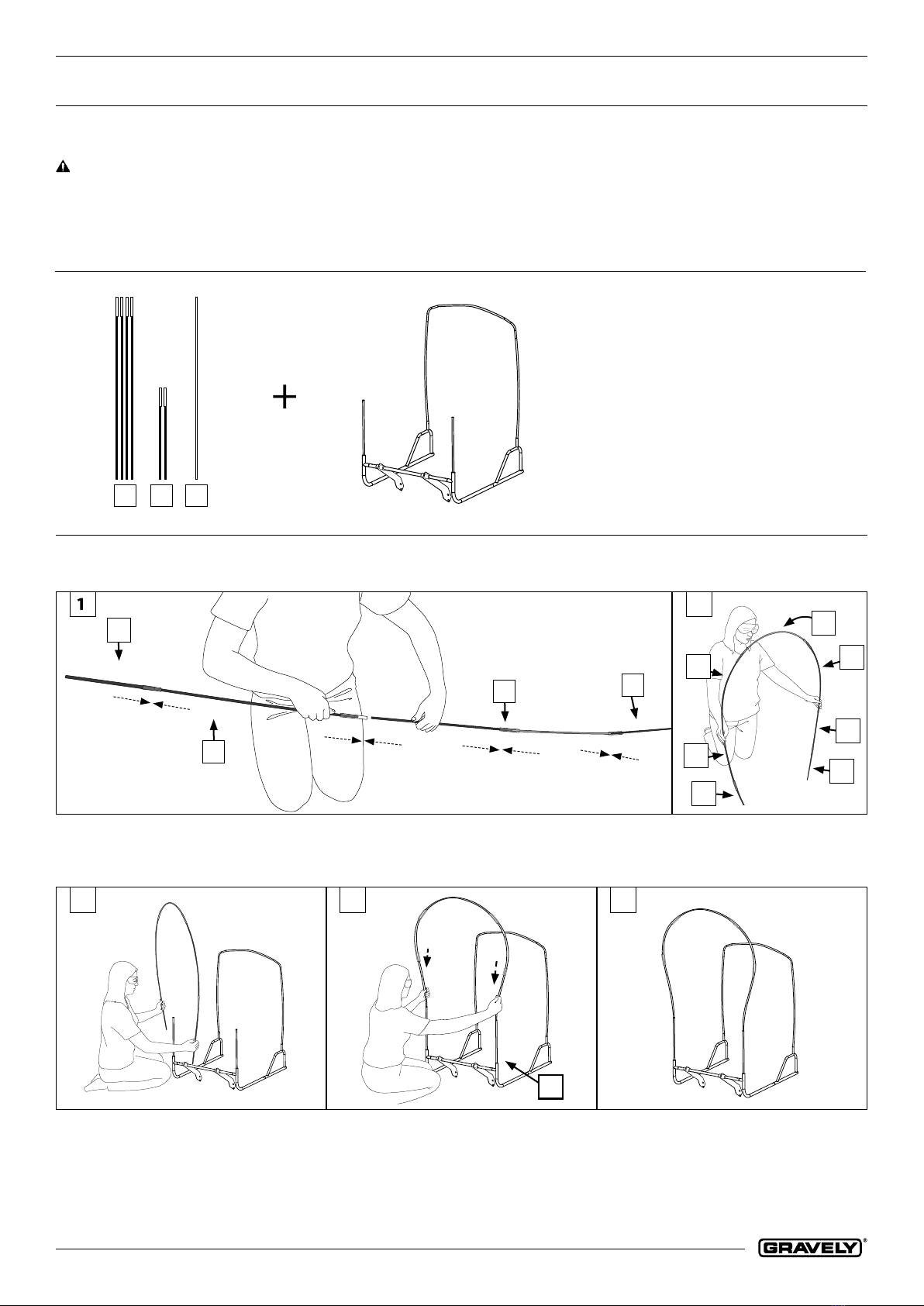
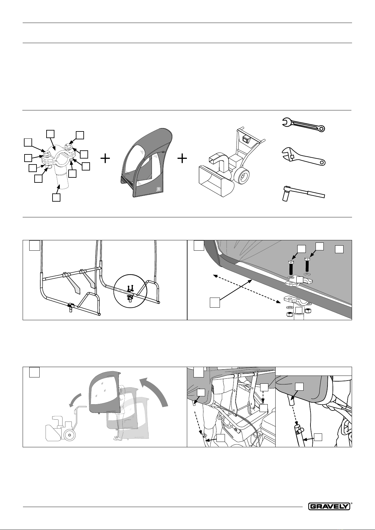
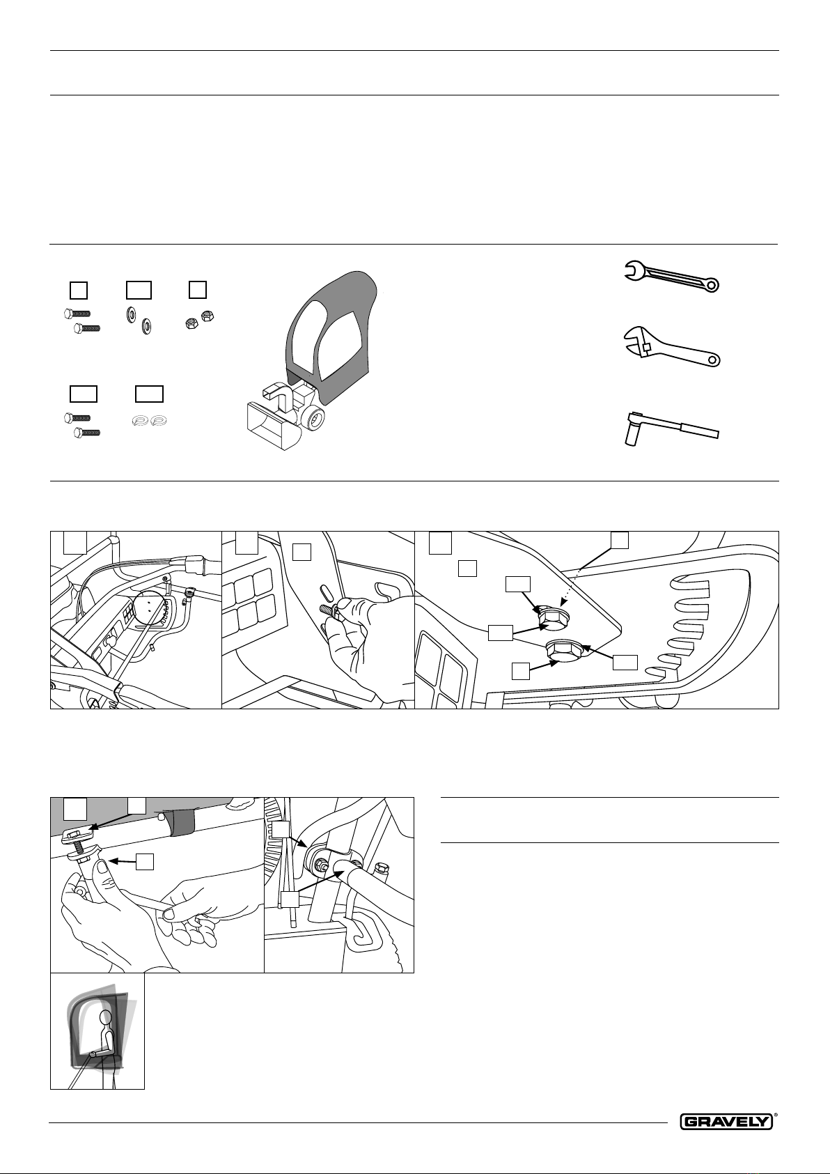
Assembly Instructions...........................................................................................................................................................................................
Care and Maintenance..........................................................................................................................................................................................
Contact Information .............................................................................................................................................................................................
ariensco.com
ARIENS COMPANY, BRILLION, WI , USA
Table of Contents