Gray DMX512 User manual

DMXPathfinder MR
Users GuideUsers Guide
Version 1.1
October 1998
Gray InterfacesGray Interfaces
480C -36 Avenue S.E.
Calgary, AB, T2G 1W4
Canada
Phone: (403) 243-8110
Fax: (403) 287-1281
E-mail: support@gray-interfaces.com
Web site: www.gray-interfaces.com

DMXPathfinder LR Contents
1
CONTENTS
INTRODUCTION ..............................................................2
WELCOME TO THE WORLD OF DMXPATHFINDER!.......................................2
CHAPTER 1: INSTALLATION AND ASSEMBLY ......................................3
SUMMARY...................................................................3
BEFORE STARTING ...........................................................3
RACK SIZING AND PLACEMENT...................................................4
MOUNTING TERMINATION BOARDS .................................................5
I/O CABLE INSTALLATION .....................................................6
MODULE PREPARATION .........................................................6
MODULE INSTALLATION ........................................................7
I/O CABLE CONNECTION.......................................................8
PATCHING .................................................................10
CHAPTER 2: MAINTENANCE & TESTING .........................................11
TESTING THE INSTALLATION...................................................11
CARD REPLACEMENT..........................................................11
TEST PROCEDURES ..........................................................12
ADVANCED TROUBLESHOOTING...................................................13

DMXPathfinder LR Introduction
2
INTRODUCTION
WELCOME TO THE WORLD OF DMXPATHFINDER!
This Installation Guide is intended to walk you through a typical installation. In
preparing the User Guide, it has been assumed that you are reasonably familiar
with the DMX512 and the various wiring methods associated with RS422/485
based protocols.
DMXPathfinder MR is a DMX512 distribution tool, providing a method for
distributing up to eight DMX sources (such as dimming or moving light controls)
to a number of DMX devices or outlets. All inputs and outputs are opto-isolated
and repeated, in conformance with the USITT/ESTA specifications for DMX512
signal distribution.
The Installer’s Guide is divided into 2 chapters:
•DMXPathfinder Installation leads you through all the steps necessary for
a “clean” installation of your hardware.
•Maintenance and Testing offers troubleshooting tips and procedures to
keep everything running smoothly.

DMXPathfinder LR Installation & Assembly
3
Chapter 1: Installation and Assembly
SUMMARY
This section describes how to correctly assemble the DMXPathfinder MR
hardware into an equipment rack and connect permanently installed external
wiring.
To ensure a trouble-free installation, you should follow this sequence:
1. Install the equipment rack
2. Run conduit and pull cable
3. Install auxiliary rack equipment and power bars
4. Mount termination boards (if applicable)
5. Dress cable in the rack and terminate (if possible)
6. Unpack the DMXPathfinder MR I/O Modules and prepare
7. Install the I/O Modules in the rack
8. Connect cabling to the I/O Modules
9. Power up and test
BEFORE STARTING
Before installing the DMXPathfinder MR equipment rack, you should
carefully consider the environment in which the equipment is to be installed, the
proximity to power sources, and the required conduit and/or cable runs.
Environmental Considerations -- To maximize equipment life and minimize
the possibility of unreliable operation or failures, the following conditions should
be adhered to:
•Ambient temperature extremes: -10 to 50 degrees C
•Recommended operating temperature: +10 to +40 degrees C
•Relative humidity: 10-95% non-condensing
•General conditions: clean, dust-free environment
Fan Cooling -- Each of the DMXPathfinder MR Output Modules is provided with
an internal cooling fan. These fans draw air in on the right hand side and
exhaust air on the left. To ensure adequate air circulation, do not block the
modules at either side. If more than two or three Output Modules are installed in

DMXPathfinder LR Installation & Assembly
4
the same rack, allow for at least a 1U ventilation panel at the top and bottom of
the rack.
Power Requirements -- A single-phase power source (50 or 60Hz, 100-
240VAC, at 0.2A per Input Module and 0.5A per Output Module) must be
provided to the DMXPathfinder MR equipment rack. It is recommended that no
more than ten I/O modules be connected to one power circuit due to the startup
current requirements of their switch-mode power supplies.
RACK SIZING AND PLACEMENT
The system installer normally supplies the DMXPathfinder MR equipment
rack. Use only a standard E.I.A. 19" rack, at least 18" deep (24" is
Isolated Power
Isolated Power
Isolated Power
Isolated Power
Isolated Power
Isolated Power
Isolated Power
Isolated Power
Isolated Power
Isolated Power
Isolated Power
Isolated Power
Main 5V Power
Main 5V Status
Main 5V Status
Talkback Data
Talkback Data
Talkback Data
Talkback Data
Talkback Data
Talkback Data
Talkback Data
Talkback Data
Talkback Data
Talkback Data
Talkback Data
Talkback Data
Input Data
MergeEnabled
MergeEnabled
TransmitData
TransmitData
TransmitData
TransmitData
TransmitData
TransmitData
TransmitData
TransmitData
TransmitData
TransmitData
TransmitData
TransmitData
Output Data
CrosspointOK
CrosspointOK
A
A
A
B
B
B
1
9
17
25
2
10
18
26
3
11
19
27
4
12
20
28
5
13
21
29
6
14
22
30
7
15
23
31
8
16
24
32
1
9
17
25
2
10
18
26
3
11
19
27
4
12
20
28
5
13
21
29
6
14
22
30
7
15
23
31
8
16
24
32
1
9
17
25
2
10
18
26
3
11
19
27
4
12
20
28
5
13
21
29
6
14
22
30
7
15
23
31
8
16
24
32
C
C
C
D
D
D
XPUXPUXPUI/O OPTO-REPEATERUNITSI/O OPTO-REPEATERUNITSI/O OPTO-REPEATERUNITS
Isolated Power SYSTEM
RESET
Receive Data
Talkback Data
A B C D EFGH
DMXPathfinderMRDMXPathfinderMRDMXPathfinderMRCrosspoint/OutputModuleCrosspoint/OutputModuleCrosspoint/OutputModule
DMXPathfinder
InputModule
Input Module
(inputs 1 - 8)
Output Module #1
(outputs 1 - 32)
Output Module #2
(outputs 33 - 64)
Output Module #3
(outputs 65 - 96)
19" Rack

DMXPathfinder LR Installation & Assembly
5
recommended). To calculate minimum height, add up the number of 2U Input
Modules and 4U Output Modules to be installed, then add at least 2U for vent
panels and allowance for power bars, connector panels or other accessories if
required. Louvered, locking front and rear doors are recommended.
Locate the rack such that at least 3 feet of clearance is allowed at the front,
2 feet at the back, and sufficient clearance at one side (preferably the left) to
permit service access to the internal cable connections.
MOUNTING TERMINATION BOARDS
One of two types of cable termination boards are normally supplied with
the system to provide the physical interface between the DMXPathfinder MR
Output Modules and external station cabling.
PORT APORT BPORT CPORT DPORT E
DMX INPUTS
PORT FPORT GPORT H
OUTPUT 5-8 OUTPUT 1-4
J2 J1
J4 J3
J6 J5
J10
J12
J9
J11 J13
J8 J7
OUTPUT 13-16 OUTPUT 9-12
OUTPUT 21-24 OUTPUT 17-20
OUTPUT 29-32 OUTPUT 25-28
INTER-MODULEBUS
INTER-MODULEBUS
INTER-MODULEBUS
32-WAY OUTPUT MODULE
PC-COM
CPS
TxD
CABLE B THRU
CABLE B IN
CABLE A THRU
CABLE A IN
RxD
COM
TxD+
TxD-
RxD+
RxD-
POWER IN
POWER IN
100-240V
100-240V 50/60Hz
50/60Hz
DMXPathfinderMR
MODEL NUMBER
SERIALNUMBER
MADE IN CANADA
100-240 VAC
50/60Hz 1.0A
111111112222 22223333 33334444 444455555555
Input Module, 8-way
Crosspoint / Output Module, 32-way
DMX Input Terminal Blocks
DMX Output Connectors, 4-way (DB25F)
PC Communications Connection (unused)Inter-Module Bus Connection
Inter-Module Bus Connector, 1-8 Inputs (DB37F)
Output Terminal Adapter Board, 32-wayLinking Cable, 37 conductor
Mains Power Supply Input
Inter-Module Bus Connector (unused)
DMX Output Terminal Blocks, 2 piece
TB32
TB24
TB16
TB8
TB31
TB23
TB15
TB7
TB30
TB22
TB14
TB6
TB29
TB21
TB13
TB5
TB28
TB20
TB12
TB4
TB27
TB19
TB11
TB3
TB26
TB18
TB10
TB2
TB25
TB17
TB9
TB1
A
A
F
B
G
KC
H
LD
E
J
M
BGC D
J
ML
FHK
E

DMXPathfinder LR Installation & Assembly
6
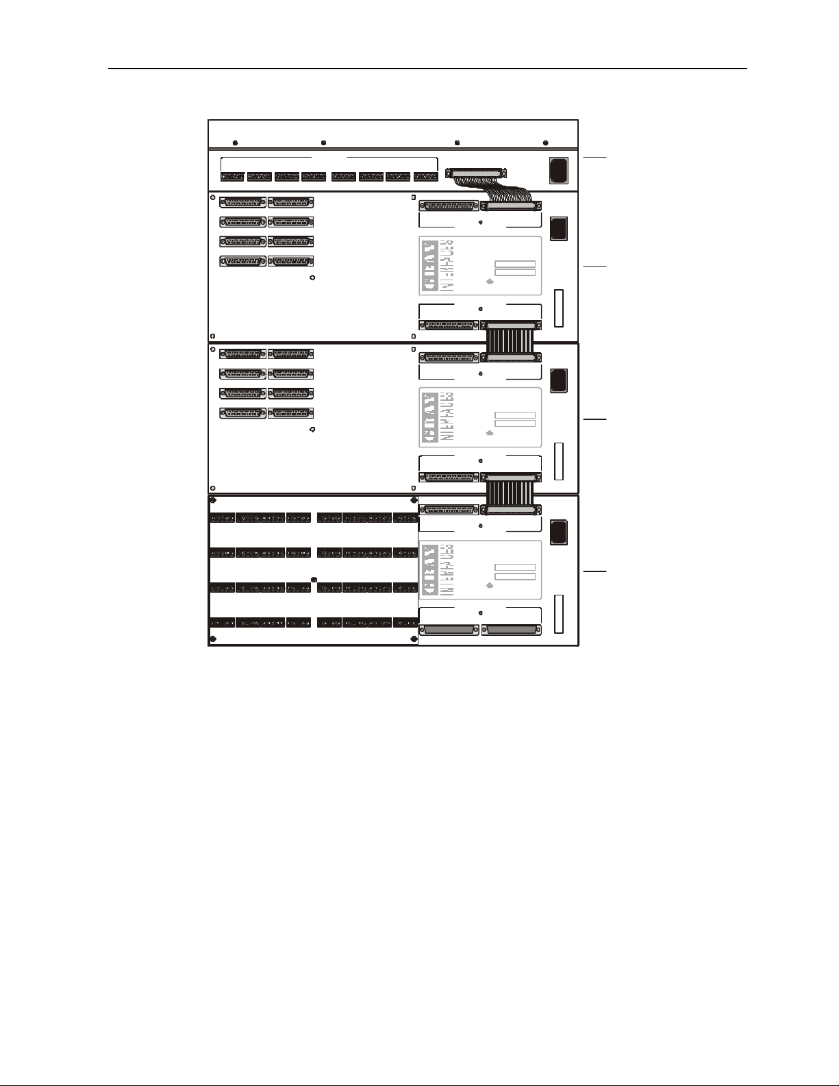
Model P2020 32-way terminal block transition boards are the most
commonly used method of connecting the DMX output station cabling. These
boards mount directly to the rear of each output module using five 6-32
standoffs and screws. They electrically connect to each Output Module with
eight 25-pin D-style connectors, therefore a certain amount of force is required
to mate the two parts. Ensure that all 8 connectors are fully mated and that the
board is resting on the standoffs before installing the five screws.
If the DMXPathfinder MRis to be installed in a swing-out (hinged) type of
equipment rack, a different type of termination board is usually supplied, the
DMS-16LT type. These are 16-way boards, intended for mounting in the rear of
the equipment rack, on the rear service panel or on 4U rack panels supplied by
the installer or the factory, depending on project requirements. 25-conductor
twisted pair ribbon cables, 1-meter long, interconnect these boards with the rear
of the DMXPathfinder MR Output Modules. Two termination boards should be
installed side-by-side on each panel. We recommend the use of 3/8"-1/2" 6-32
threaded standoffs and 1/4" screws to attach the boards to the mounting panels.
Insulated hardware is not necessary.
Using DMS-16LT termination boards, mounting and external station
cabling may be completed well in advance of installation of the rest of the
DMXPathfinder MR hardware.
I/O CABLE INSTALLATION
Input and Output cabling may enter the equipment rack through the top or
bottom. Bundle cables at either side of the rack, just in front of the termination
boards. Cabling installed to the rear of the rack from the panels will obscure
access to terminal blocks at the extreme edges of the termination boards.
Cables are then dressed into place for connection at the input/output
terminal blocks. Note the order of the terminal blocks. On 32-way boards they
are labeled TB1 to TB32 and are arranged right to left, top to bottom. On 16-
way boards they are labeled TB1 to TB16 and are arranged top to bottom, left
to right.
MODULE PREPARATION

DMXPathfinder LR Installation & Assembly
7
Unpack all of the DMXPathfinder MR system modules and accessories
and arrange on a flat surface. First, locate the package of screws supplied with
each module, and use 8-32 screws to attach the rack mount ears to the sides of
each Input and Output Module.
If P2020 type termination boards are to be used, mate them to each
Output Module and fasten with 5 x 6-32 screws.
Using one power cord, power up each Input and Output Module one at a
time and verify that the main power LEDs illuminate.
Remove the four adhesive rubber feetfrom the bottom of each module.
MODULE INSTALLATION
Starting with the last (bottom) Output Module, install the modules into the
equipment rack. Normally the Input Module is located above the Output
Modules, but it can be placed at the bottom, if desired. In any case the Input
Module may not be placed between Output Modules.
Locate the 37-conductor ribbon cable jumpers and 37-pin bus
terminator(s). There should be one 8” long cable for the Input Module and one
4” short cable per Output Module.
Attach the long jumper cable from the Input Module to the top Inter-Module
Bus connector marked “CABLE A IN”. Install the short ribbon cable jumpers
between Output Modules. The bottom connector marked CABLE A THRU on
one module connects to the top (IN) connector on the next lower module in all
cases.
Install the 37-pin bus terminator plug at the bottom or last unconnected
CABLE A THRU jacks in the system.
It is unnecessary to connect anything to the CABLE B jacks on the Output
Modules, however if additional jumper cables have been supplied it’s a good
idea to install them there for possible future upgrades.

DMXPathfinder LR Installation & Assembly
8
I/O CABLE CONNECTION
Strip back about 3 inches (8cm) of cable jacket and braid shield from each input
or output cable. Apply a 2.5" (6.5cm) piece of 1/16" heat shrink to the drain wire
and a 1" (2.5cm) piece of 3/8" heat shrink over the exposed braid ends where
each cable was stripped. These precautions are to ensure that cable shields
cannot contact each other or equipment ground.
Strip about 1/2" of insulation from the four signal wires in each cable.
Bend over 1/4" of the exposed conductors on all five wires and connect them to
the terminal block. Note that each five-position terminal block is numbered 1
thru 5 on the termination board. This corresponds to the pin numbering on XLR
5-pin connectors, that is:
INTER-MODULE BUSPORT APORT BPORT CPORT DPORT E
DMX INPUTS
PORT FPORT G
PORT H
OUTPUT 5-8
OUTPUT 5-8
OUTPUT 1-4
OUTPUT 1-4
J2
J2
J1
J1
J4
J4
J3
J3
J6
J6
J5
J5
J10
J10
J12
J12
J9
J9
J9
J11
J11
J11
J13
J8
J8
J7
J7
OUTPUT 13-16
OUTPUT 13-16
OUTPUT 9-12
OUTPUT 9-12
OUTPUT 21-24
OUTPUT 21-24
OUTPUT 17-20
OUTPUT 17-20
OUTPUT 29-32
OUTPUT 29-32
OUTPUT 25-28
OUTPUT 25-28
INTER-MODULE BUS
INTER-MODULE BUS
INTER-MODULE BUS
INTER-MODULE BUS
INTER-MODULE BUS
INTER-MODULE BUS
PC-COM CPS
TxD
CABLE B THRU
CABLE B THRU
CABLE B THRU
CABLE B IN
CABLE B IN
CABLE B IN
CABLE A THRU
CABLE A THRU
CABLE A THRU
CABLE A IN
CABLE A IN
CABLE A IN
RxD
COM
TxD+
TxD-
RxD+
RxD-
J13
PC-COM CPS
TxD
RxD
COM
TxD+
TxD-
RxD+
RxD-
J13
PC-COM CPS
TxD
RxD
COM
TxD+
TxD-
RxD+
RxD-
POWER IN
POWER IN
POWER IN
POWER IN
100-240V
100-240V 50/60Hz
100-240V
100-240V
50/60Hz
50/60Hz
50/60Hz
1 1 1 1 1 1 1 12 2 2 2 2 2 2 23 3 3 3 3 3 3 34 4 4 4 4 4 4 45 5 5 5 5 5 5 5
TB32
TB24
TB16
TB8
TB31
TB23
TB15
TB7
TB30
TB22
TB14
TB6
TB29
TB21
TB13
TB5
TB28
TB20
TB12
TB4
TB27
TB19
TB11
TB3
TB26
TB18
TB10
TB2
TB25
TB17
TB9
TB1
Input Module
(inputs 1 - 8)
Output Module #1
(outputs 1 - 32)
Output Module #2
(outputs 33 - 64)
Output Module #3
(outputs 65 - 96)
32-WAY OUTPUT MODULE
DMXPathfinder MR
MODEL NUMBER
SERIAL NUMBER
MADE IN CANADA
100-250VAC
50/60Hz1.0A
32-WAY OUTPUT MODULE
DMXPathfinder MR
MODEL NUMBER
SERIAL NUMBER
MADE IN CANADA
100-250VAC
50/60Hz1.0A
32-WAY OUTPUT MODULE
DMXPathfinder MR
MODEL NUMBER
SERIAL NUMBER
MADE IN CANADA
100-240VAC
50/60Hz1.0A

DMXPathfinder LR Installation & Assembly
9
Pin 1 -- Signal Common (shield)
Pin 2 –DMX Data (-)
Pin 3 –DMX Data (+)
Pin 4 –Talkback Data (-)
Pin 5 –Talkback Data (+)
Be sure to use one twisted pair for the DMX data and the other for Talkback
data. It is also good practice to label each station cable and corresponding
terminal block header position with the cable number.
Input Modules are provided with both 5-position rear-mounted terminal blocks
and parallel 5-pin XLR male faceplate jacks. In some installations, the
hardwired cable terminates at female jacks mounted on an auxiliary panel
provided by the system supplier. In this case, no connection is made to the
Input Module’s rear terminal blocks; instead short XLR patch cables are used to
interconnect the auxiliary panel female jacks with the Input Module’s male
faceplate jacks.

DMXPathfinder LR Installation & Assembly
10
Patching
To assign outputs to inputs, first remove the front cover to access the Crosspoint
Card (E).
Each of the 32 rotary selector switches on the Crosspoint Card corresponds to
an output in this Output Module. The switch is set to the input number from one
to eight that you wish to feed this output from. Position one corresponds to input
“A” and position eight to input “H”. Positions zero and nine are unused.
0
1
2
3
4
5
6
7
8
9
0
1
2
3
4
5
6
7
8
9
0
1
2
3
4
5
6
7
8
9
0
1
2
3
4
5
6
7
8
9
0
1
2
3
4
5
6
7
8
9
0
1
2
3
4
5
6
7
8
9
0
1
2
3
4
5
6
7
8
9
0
1
2
3
4
5
6
7
8
9
0
1
2
3
4
5
6
7
8
9
0
1
2
3
4
5
6
7
8
9
0
1
2
3
4
5
6
7
8
9
0
1
2
3
4
5
6
7
8
9
0
1
2
3
4
5
6
7
8
9
0
1
2
3
4
5
6
7
8
9
0
1
2
3
4
5
6
7
8
9
0
1
2
3
4
5
6
7
8
9
ROUTER ASSIGNMENT
SW1 thru SW32
JUMPER SETTINGS
* indicates factory default setting
MODULECONFIGURATION
Eachswitchsetsroutingfor
oneDMXoutputline.Switch
positionnumbers"1"thru"8"
correspondtoDMXinputs"A"
thru"H".Donotusepositions
"0"&"9".
Example:
Torouteinput"D"tooutput25
setSW25to"4".
JP1/Motherboard
open = fan ON
*shorted = fan OFF
JP1/Output Card
*open = power ON
shorted = CPU power control
(used with LR version only)
A
B
CF
D
E
0
1
2
3
4
5
6
7
8
9
0
1
2
3
4
5
6
7
8
9
0
1
2
3
4
5
6
7
8
9
0
1
2
3
4
5
6
7
8
9
0
1
2
3
4
5
6
7
8
9
0
1
2
3
4
5
6
7
8
9
0
1
2
3
4
5
6
7
8
9
0
1
2
3
4
5
6
7
8
9
0
1
2
3
4
5
6
7
8
9
0
1
2
3
4
5
6
7
8
9
0
1
2
3
4
5
6
7
8
9

DMXPathfinder LR Index
11
Chapter 2: Maintenance & Testing
TESTING THE INSTALLATION
Once all connections are made and inspected for possible errors, you can
power up the DMXPathfinder MR modules in the equipment rack. With no
DMX source signals or talkback signals present, all eight red Isolated Power
LEDs on the face of the Input Module should be illuminated. On each Output
Module, all eight red Isolated Power LEDs on each installed output card and the
Main 5V Power LED on the crosspoint card (XPU) should be illuminated. If any
green or amber LEDs are on, there may be a wiring problem with the external
DMX cabling. Try disconnecting the corresponding input or output temporarily
to see whether this is the case.
CARD REPLACEMENT
Should a defective component be found in an Output Module or other
module during troubleshooting, it is best to replace the suspected defective
circuit card with a spare unit and re-test. Powering down the entire
DMXPathfinder, or at least the specific module, is recommended before
removing or inserting cards.
0
1
2
3
4
5
6
7
8
9
0
1
2
3
4
5
6
7
8
9
0
1
2
3
4
5
6
7
8
9
0
1
2
3
4
5
6
7
8
9
0
1
2
3
4
5
6
7
8
9
0
1
2
3
4
5
6
7
8
9
0
1
2
3
4
5
6
7
8
9
0
1
2
3
4
5
6
7
8
9
0
1
2
3
4
5
6
7
8
9
0
1
2
3
4
5
6
7
8
9
0
1
2
3
4
5
6
7
8
9
0
1
2
3
4
5
6
7
8
9
0
1
2
3
4
5
6
7
8
9
0
1
2
3
4
5
6
7
8
9
0
1
2
3
4
5
6
7
8
9
0
1
2
3
4
5
6
7
8
9
ROUTER ASSIGNMENT
SW1 thru SW32
JUMPER SETTINGS
* indicates factory default setting
MODULECONFIGURATION
Each switch sets routing for
one DMX output line. Switch
position numbers "1" thru "8"
correspond to DMX inputs "A"
thru "H". Do not use positions
"0" & "9".
Example:
To route input "D" to output 25
set SW25 to "4".
JP1/Motherboard
open = fan ON
*shorted = fan OFF
JP1/Output Card
*open = power ON
shorted = CPU power control
(used with LR version only)
A
A
B
B
CF
C
D
D
F
E
Output card #1 (CH. 1-8) part # 2108
Output card #2 (CH. 9-16) part # 2108
Output card #3 (CH. 17-24) part # 2108
Output card #4 (CH. 25-32) part # 2108
Crosspoint card part # 2320
Output module (MR) part # 2300
E

DMXPathfinder LR Index
12
To replace an Output Module card, first remove the four front-panel Phillips
screws and the cover panel, then grasp the card stiffener bracket (or ejector
handles), and pull the card straight out of the module chassis. Carefully align the
replacement circuit board into the chassis' left and right card guides and slide
the unit in until it protrudes about 5mm, then push the module firmly into its
mating backplane receptacles. The card is not fully seated unless its front edge
is flush with the front of the metal chassis.
If the Crosspoint Card was replaced, check that the rotary switches have
been set the same as the replaced card. Test the system to ensure that the fault
has been corrected.
TEST PROCEDURES
System testing by maintenance personnel will usually be carried out in
response to a fault that has developed somewhere in the system. Powerful
diagnostic instruments are available to assist maintenance technicians with this
task: the Fluke Model 650 LAN Cable Meter, and Goddard Design Li'l DMX'ter,
amongst others. These will be described in more detail below. In general,
though, the troubleshooting instructions in this chapter arelikely to help solve the
vast majority of problems encountered, especially where any system downtime
cannot be tolerated.
Tests using instrumentation will be performed where anomalies have
developed in the system that cannot be isolated with standard troubleshooting
procedures. Additionally, testing can establish minimum network performance
where non-DMX512 control equipment is to be connected to the system.
Fluke 650 Cable Meter -- Please refer to the manufacturer's user's
manual for detailed instructions and theory before attempting to use this
instrument. It’s not obvious to the first time user! The Fluke 650 is provided with
a battery-powered remote plug-in unit, a set of 2 adapter cables (RJ45 to 5-pin
XLR) and an AC adapter. The unit may be powered by a 9-volt alkaline battery,
but battery life tends to be rather short with the 650 so use of the AC adapter is
recommended.
When the remote unit is connected to the other end of any DMX cable run,
the 650 will verify wiring continuity on all pins except ground (pin 1). Cable
length can also be measured with the instrument, and any anomalies, e.g.
changes in line impedance will be detected. The 650 measures performance of
the cable installation at up to 10 million bits per second.

DMXPathfinder LR Index
13
The Fluke 650's signalling is not compatible with the DMXPathfinder MR
electronics or any other DMX generating or receiving equipment. Thus its
usage should be confined to the cable installation only.
Goddard Design Li'l DMX'ter -- This useful instrument can test most
aspects of the DMX Distribution System, from wiring continuity to signal
propagation through the DMXPathfinder electronics. Since the DMX'ter can
both generate and receive DMX512, it is 100% compatible with all aspects of
the distribution system, including any control system or receiving device. The
DMX'ter will directly control any receiving unit, and will verify the output of a
controller by displaying the data on an LCD readout. In addition, the instrument
will test cable continuity on all five XLR pins. Please refer to the Li'l DMX'ter
Operating Manual for more information.
Other Test Equipment -- The maintenance technician will find the
following additional test equipment useful:
.1 Oscilloscope -- for viewing data in conjunction with the
DMX'ter and its scope trigger module; for checking that both differential signals
are present on a given data line; for evaluating the performance of crosspoint
matrix and opto-repeater circuitry at higher operating speeds (greater than 250
Kbits per second).
.2 Frequency Generator -- for testing crosspoint matrix and
opto-repeater high-speed performance. Useful for evaluating whether other
systems with higher data rates can be used in the network.
.3 Digital Volt/Ohm Meter -- a general purpose tool for
checking continuity, termination resistor values and power supplies.
ADVANCED TROUBLESHOOTING
As described earlier, basic troubleshooting usually involves isolating a
troublesome or defective opto-repeater circuit, card or module and replacing it
with a known good one. It may also include checking for obvious things such as
incorrect addressing or DMX protocol incompatibility with DMX receiving
devices, absence of a line terminator, defective DMX patch cables, or even
incorrect control console configuration.
Once all basic troubleshooting checks have been completed, without the
desired resolution of the problem, more sophisticated faultfinding may be

DMXPathfinder LR Index
14
carried out. Try swapping input or output cable connections on the back of the
DMXPathfinder modules with adjacent ones to use a different receiver and
transmitter circuits. Next, a DMX tester should be used to either transmit DMX
in place of the control console, or receive DMX in place of the receiving
device(s). Check the receiving device by connecting the DMX tester directly to
it in transmit mode. Then set the tester to receive mode and monitor the data
coming to the DMXPathfinder from the console, by plugging into the Input
Module faceplate XLR with a female-female cable. If this test does not point to
the data source or the receiving device as being the cause of the problem, there
may be a slight incompatibility between them as far as DMX512 is concerned.
However, if the two units hadpreviously worked together, these tests will point to
a problem in the DMX cable installation or in one of the DMXPathfinder
modules.
At this point, the suspect Output Module’s output card or should be
withdrawn from its chassis and the spare unit inserted in its place (remember to
power down before withdrawing or inserting any cards). If this proves that the
original unit is defective, inspect the card for signs of damage or any other
obvious cause. Return the defective card to the factory for repair unless you
have the facilities to carry out your own service. For more serious defects, such
as power supply or fan failure, disconnect the entire module and take it to the
test bench for repair, or return it to the factory. DMXPathfinder MR modules are
not difficult to service with basic tools and test equipment. If the suspect module
proves to be good, test the DMX cable installation for open or shorted lines
using a loopback test connector. You can easily make one of these from a 5-pin
male XLR plug by shorting together pins 2&4 and 3&5. Insert the plug into the
female DMX-out receptacle at the far end of the cable and apply a DMX signal
to the desired DMXPathfinder input. Switch-select that input at the crosspoint
card. If the wiring installation is good, the green & amber LEDs on the Input
Module, crosspoint card and output card will all be illuminated. Note that this
test is possible only in systems where all five XLR pins are wired.
If the above tests yield passing results and the problem persists, it may be
necessary to use the Fluke LAN Cable Meter to do a high-frequency analysis of
the suspect cable runs. This test will quickly indicate any anomalies having to
do with cable impedance and capacitance that would result in excessive signal
distortion or attenuation. This test will help to locate less-obvious problems such
as pinched or over-heated cabling that cannot be found with simple continuity
checks.

DMXPathfinder LR Index
15
INDEX
A
Advanced Troubleshooting ·
13
Ambient temperature · 3
Assembly · 3
B
bus terminator · 7
C
CABLE A IN · 7
CABLE A(B) THRU · 7
CABLE B IN · 7
cabling · 6
Card Replacement · 11
control console · 13
Cooling · 3
Crosspoint card · 10
Crosspoint OK LED · 11
D
diagnostic instruments · 12
Digital Volt/Ohm Meter · 13
DIP switches · 12
DMS-16LT · 6
DMX · 2, 11
DMX Data · 9
DMX distribution system · 13
DMX'ter · 13
E
Environmental Considerations
· 3
equipment rack · 3, 4, 6, 7, 11
F
Fan · 3
Frequency Generator · 13
G
Goddard Design · 13
H
humidity · 3
I
I/O Cable Connection · 8
I/O Cable Installation · 6
Input Module · 5, 7, 11
Installation · 3
installer · 4
Inter-Module Bus connector ·
7
Isolated Power LED · 11
L
LAN Cable Meter · 12, 14
Li'l DMX'ter · 12, 13
Loopback Test · 14
M
Main 5V Power LED · 11
Module Installation · 7
Module Preparation · 7
O
opto-repeater · 13
Oscilloscope · 13
output card · 14
Output Module · 5, 6, 7, 10, 11,
14
P
P2020 · 6, 7
Patching · 10
Power Requirements · 4
Processor OK LED · 11
R
Rack Placement · 4
Rack Sizing · 4
Relative humidity · 3
ribbon cable · 6, 7
rotary switches · 10
rubber feet · 7
S
Signal common · 9
System testing · 12
T
Talkback · 9
temperature · 3
terminal block · 6, 9
termination boards · 3, 5
Test Procedures · 12
TESTING · 11
Testing the Installation · 11
transition boards · 6
troubleshooting · 11, 13
V
vent · 4
X
XLR · 9, 14
Table of contents