Gray QUICKPAC QP-50 User manual

OWNER’S MANUAL
QP-50
QUICKPAC
TM
Container Crusher
READ THIS MANUAL CAREFULLY
AND RETAIN FOR YOUR RECORDS

ii
Table of Contents
QUICKPACTM.......................................................................................................................................i
Receiving Inspection and Installation....................................................................................................1
Introduction...........................................................................................................................................1
Owner and / or Operator Responsibilities.................................................................................................1
Specifications........................................................................................................................................2
Component Identification ......................................................................................................................3
Features...................................................................................................................................................3
Safety Instructions ................................................................................................................................4
Safety Instructions for Transporting Unit...................................................................................................4
Operating Instructions...........................................................................................................................5
Door Handle Operation ............................................................................................................................5
Maintenance Instructions......................................................................................................................5
Control Valve Actuation Adjustment.........................................................................................................6
Structural Inspection.............................................................................................................................6
Troubleshooting....................................................................................................................................7
Notes ....................................................................................................................................................8
Notes ....................................................................................................................................................9
Foreword
Thank you for your purchase. With Gray products, you take part in a long history of product engineering for the
transportation service industry. Company founder J. H. Gray applied for his first automotive jack patent in
1921, and since 1952 Gray has been producing the highest quality hydraulic and pneumatic equipment available
for the professional service technician. Our purpose is to provide you with quality equipment that makes your
job easier and with exemplary service after the sale. Please call Gray's customer service, at 1-800-821-7320 or
816-233-6121, with any comments or questions.

1
Receiving Inspection and Installation
Before attempting to operate this unit, thoroughly read and understand this manual. Completely remove all tape
and packaging. Inspect the unit immediately upon delivery. If shipping damage is evident, inform the
delivering carrier immediately and contact customer service at the numbers and address printed on the back
cover of this manual.
Locate a suitable place in your shop to install the unit. This unit must be installed indoors on a level surface.
The unit is required to be anchor bolted to a concrete floor, for safe operation.
This unit is shipped in a lowered position. First, position the crusher in the desired location in your shop.
Second, mark the floor for the anchor bolt location to match the holes in the base of the stand. Four 3/8 or 1/2
inch diameter anchor bolts are recommended to install the unit. Install the anchor bolts according to the
manufacturer’s instructions. Secure the unit to the floor with the anchor bolts.
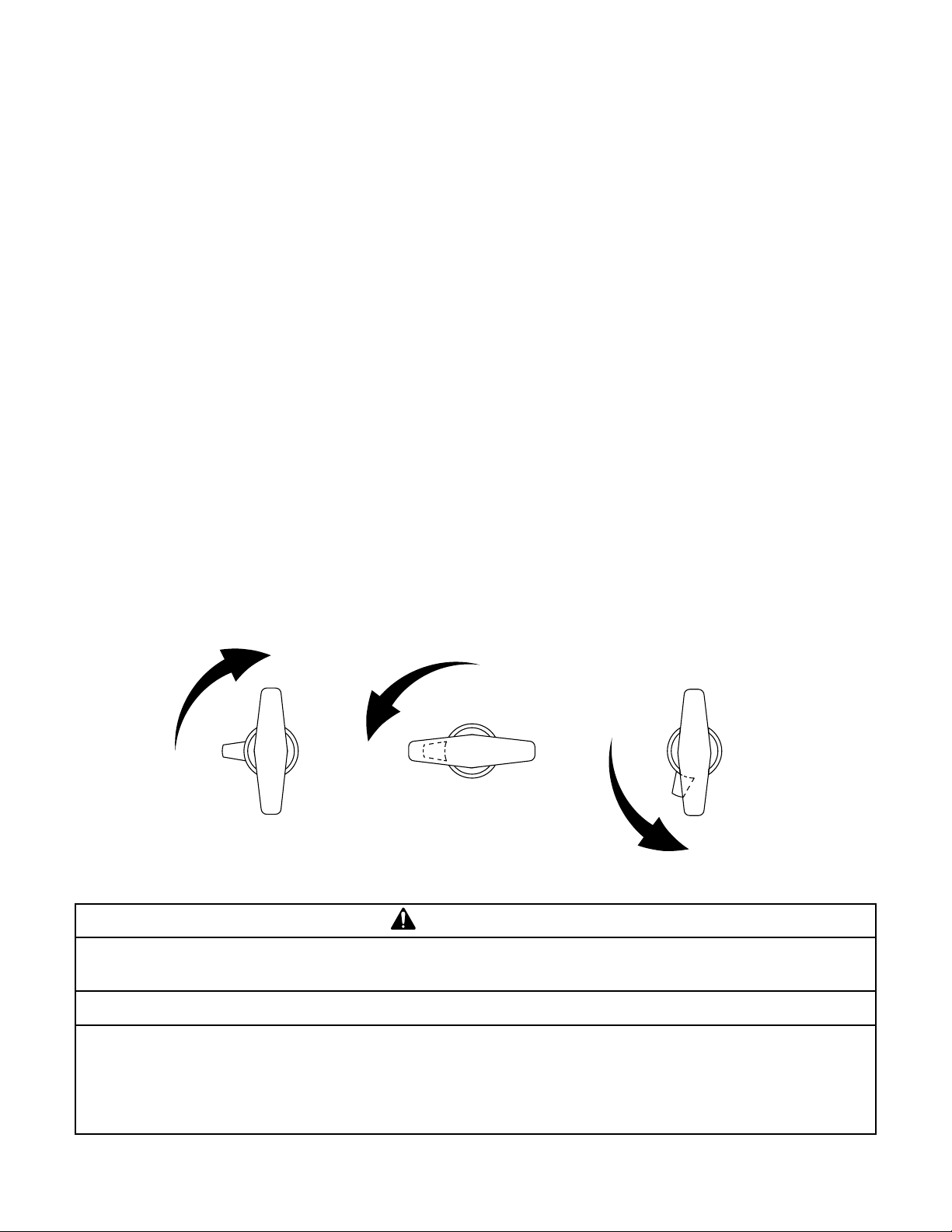
The unit is shipped also with the crushing module fastened to the stand in a lowered position. Caution: The
crushing module weighs 210 lb. and we recommend using a shop crane capable of handling the load or lift truck
to perform the lifting. Remove the bolt and nut from the stand post, do not remove the 5/16 inch screw from the
top of the post. Raise the crushing module from the shipping position to the working position. Align the hole
on the tube on the crushing module with the hole from the hole in the stand post and insert the bolt provided.
Secure with the nut on the bolt.
Connect the catch basin to the appropriate waste oil container as required by national, state, or local regulations.
The catch basin connection is a 3/4 FNPT fitting located on the bottom or on the side. If the opposite side
connection is desired, simply remove the catch basin and install with the connection on the desired side. The
unit may be connected using 3/4 male pipe to a remote waste oil tank. Another option is to connect the catch
basin to a drum. Use 3/4 pipe close nipple, a 1 in. I.D. oil resistant hose and a hose clamp to connect the hose to
the catch basin. Install the hose in the bung of the drum and cut the length of the hose so it will fit in the drum 2
to 4 in. The installation must provide for the easy removal of the catch basin as sludge and semi-solid residue
from oil filters may accumulate. The catch basin requires periodic cleaning to remove solid residues. All such
residues must be transferred to an acceptable container.
If the unit is to be used solely for crushing empty paint cans, the catch basin does not need to be connected to
any container. However, a drip pan should be placed beneath it or the pipe drain fittings should be plugged. The
installation of the unit should provide for easy removal of the catch basin to remove inadvertent spills and
foreign material, which may accumulate in the catch basin.
Connect the air supply to the air inlet. The inlet connection is 1/4 FNPT. The unit is now ready for use.
Recommended operating air pressure is 100-PSI minimum for most paint cans and car and light truck filters.
Maximum recommended air pressure is 200 PSI.
If for any reason the unit does not operate properly after reviewing the steps above consult the Troubleshooting
section in this Owner’s Manual or call customer service at the numbers and address printed on the back cover of
this manual for further instructions and assistance. Please have the model number and serial number of your
crushing equipment available. The serial number is permanently stamped on the inside of the door.
Introduction
Owner and / or Operator Responsibilities
Used oil and used oil filters are subject to national, state and local regulations. Crushing used oil filters is an
effective method for removing a large percentage of me remaining oil trapped in the used filter. The owner of

2
this machine is responsible for meeting all of those applicable regulations such as the handling and storage of
used, crushed or uncrushed oil filters, the handling and storage of used oil, and appropriate recycling or disposal
of used oil filters and used oil.
The owner and / or user must have an understanding of the manufacturer’s operating instructions and warnings
before using this jack. Personnel involved in the use and operation of equipment shall be careful, competent,
trained, and qualified in the safe operation of the equipment and its proper use. Persons impaired by
medication, drugs or alcohol must not use crushing equipment. Examples of unsafe operations include using the
this unit to crush items it is not intended to crush, modification of this machine, using this machine as a press,
circumventing or disabling the valve actuation or door interlock mechanism, and failure to wear safety glasses
and gloves while operating the crushing equipment or handling used oil filters and paint containers. Warning
information should be emphasized and understood.
The owner / manager must make this manual available to all personnel using this jack. They must read and
understand the contents of this manual. If the operator is not fluent in English, the manufacturer’s instructions
and warnings shall be read to and discussed with the operator in the operator’s native language by the purchaser
/ owner, making sure that the operator comprehends its contents and observes the proper procedures for use of
this jack.
Owner and / or user must study and maintain for future reference the manufacturer’s instructions. Owner and /
or user are responsible for keeping all warning labels and instruction manuals legible and intact. Replacement
labels and literature are available from the manufacturer.
Specifications
Height.............................................................................................................77 1/8 inches
Width..............................................................................................................20 1/2 inches
Depth..............................................................................................................16 3/4 inches
Weight............................................................................................................242 lbs.
Crushing Chamber
Height.............................................................................................................9 inches
Width..............................................................................................................8 inches
Depth..............................................................................................................8 inches
Air Inlet..........................................................................................................1/4 female npt.
Air Pressure....................................................................................................100 to 160 psi
Catch Basin Connection.................................................................................3/4 female npt.

3
Component Identification
Features
Pneumatic Powered Ram: Pneumatic power gives you the advantages of long life, low maintenance, and
quick crushing action. Also no electrical connections are required eliminating the electrical hazard and the
problems of dirty and/or faulty connections.
Interlocking Door: The door interlock restrains the door from opening until the ram is fully raised.
Convenient Operation: One hand is required to close the door and latch it. After the door is latched, the
crushing chamber is completely enclosed to prevent injuries and to prevent oil splatter.
Versatile Installation: The stand is standard with the unit, not optional as with many competitors’ equipment.
When crushing oil filters, the catch basin can be connected to the bottom or either side to a variety of waste oil
containers. The unit can be placed over a workbench by placing the stand post behind the workbench.
Large Crushing Chamber: Automotive spin-on filters and up to 1-gallon paint cans can be accommodated in
the crushing chamber.

4
Safety Instructions
WARNING
To avoid serious injury or death, read this manual carefully before operating this unit. Call customer
service at the numbers and address printed on the back cover of this manual if you have any questions.
Failure to understand and obey safety instructions may result in unsafe or improper use of this product.
1. The unit is required to be anchor bolted to a level concrete floor, for safe operation. It is
recommended to anchor the machine to the floor with four 3/8 or 1/2 in. diameter anchor bolts.
2. This unit is recommended for crushing spin-on oil filters, cartridge oil filters with paper
elements, and empty paint cans up to 1 gallon in size. Do not crush aerosol cans, cylinders of
compressed gas, fuel filters, or containers of flammable liquids or solvents.
3. Do not modify this unit or alter the operation in any way to circumvent the interlocking door
mechanism. Modifications to the machine will void all warranties expressed or implied.
4. Do not smoke when operating this unit and do not operate this unit when someone else in the
vicinity is smoking.
5. Wear safety glasses and gloves when operating the unit and handling the crushed oil filters and
paint cans.
6. When loading and unloading oil filters, never hold the filter by the top. Always hold the filter by
the sides with the gasket end down.
7. Do not use this unit to perform any operations other than to crush oil filters or empty paint cans.
This unit is for crushing spin-on oil filters, cartridge oil filters with paper elements, and empty
paint cans up to 1 gallon in size. Paint from full or partially full cans can solidify and clog the
holes in the catch basin.
8. Clean up any spilled oil immediately so it will not cause a slipping hazard.
9. Do not stack oil filters inside the crushing chamber.
10. Do not use outside in cold weather, it may cause air leakage and reduce crushing ability of unit.
Failure to understand and obey this warning may result in personal injury and / or property damage.
Safety Instructions for Transporting Unit
WARNING
Failure to understand and obey safety instructions may result in unsafe or improper use of this product.
Failure to understand and obey this warning may result in injury and / or property damage.
The crushing module weighs 210 lbs. and we recommend using a shop crane capable of handling the load or lift
truck to perform the lifting. Do not move the unit with the crushing module in the raised position. Always

5
lower the crushing module to its shipping position. The unit is top heavy and can tip over if the crushing
module is raised and the unit is not anchored to the floor.
Operating
Instructions
Place empty paint can with the lid removed or oil filter with the open end down in the center of the crushing
chamber.
Close door and turn door handle clockwise approximately 180 degrees. You may walk away to perform other
tasks. Upon returning, the filter or paint can will be crushed. If you want to crush containers in succession,
listen for air to stop flowing (up to 45 seconds). Some noise and vibration usually accompany the crushing
process.
To remove the crushed paint can or filter, turn the door handle counterclockwise and air will exhaust from the
ram cylinder. The door will not open until the ram is fully raised (approximately 10 seconds). Open the door
and remove the crushed, empty paint can or oil filter.
Note: A filter may be crushed for extended periods of time. The unit can be left under pressure until the next
filter or can is ready for crushing. You may crush several filters at one time provided they are all of similar
height and you have adequate air pressure. The catch basin outlet can become clogged with sludge and semi-
solid waste from filters. It is necessary to remove the catch basin and clean it periodically. Deposit solid residue
in acceptable containers. The oil level in the catch basin can be viewed through the opening beneath the door
when the door is closed.
Door Handle Operation
Door closed and handle fully
turned clockwise, door is latched
and ram extends.
Door closed and handle turned
90 degrees counter-clockwise,
air exhausts, ram retracts and
door remains closed.
Handle turned fully counter-
clockwise, air exhausts and ram
retracts, door will open when
ram is fully retracted.
Maintenance Instructions
WARNING
All inspection and maintenance procedures must be performed after the jack has been removed from
service. Failure to heed this warning may result in personal and / or property damage.
NOTICE
The owner must inspect, or appoint a knowledgeable person to inspect, the jack. Visual inspection
should be made before each use of jack, checking for abnormal conditions. Regular inspections should
be made weekly for daily use and monthly for intermittent use. Each jack must be inspected
immediately if subjected to an abnormal load or shock. Any jack which appears to be damaged in any
way, is found to be badly worn, or operates abnormally shall be removed from service until necessary

6
repairs are made.
1. All warning and capacity labels should be readable and complete. Wash external surfaces of unit and
decals with a mild soap solution.
2. Clean and/or remove sludge or foreign objects from the crushing chamber.
3. Remove the catch basin and clean the sludge, semi-solid waste, and foreign material. Make sure the
catch basin outlet is clear.
4. If using oil filters with paper elements, be sure to remove foreign material from catch basin to prevent
catch basin outlets from becoming clogged.
Control Valve Actuation Adjustment
Note: The setscrew on the door that actuates the control valve and the pawl on the door handle latch are
adjusted at the factory and should never need adjustment.
1. Make sure the two screws securing the control valve on the right hand side of the unit are tight. Make
sure the two screws securing the handle latch to the door are tight and the two jam nuts securing the
latch pawl to the stem are tight.
2. Loosen the jam nut securing the set screw on the door and back the setscrew out. Close door and turn
door handle fully clockwise to solidly latch the door.
3. Using a hex wrench, slowly tighten the setscrew until the top platen lowers and there is no air leakage
detected around the spool of the control valve. Tighten the setscrew 1/2 turn further and secure the
setscrew with the jam nut.
4. Rotate the latch handle 1/4 turn counter-clockwise. The air should exhaust and the ram should retract,
but the pawl should remain loosely engaged with the door closed.
5. Rotate the latch fully counter-clockwise and the door should open. Repeat steps 2 through 5 if the door
does not operate correctly.
Structural Inspection
WARNING
The jack must be removed from service and inspected for damage immediately if the jack is subjected to
an abnormal shock or load. Failure to heed this warning may result in personal and / or property
damage.
NOTICE
The owner must inspect, or appoint a knowledgeable person to inspect the jack for signs of corrosion
and / or excessive wear. Visual inspection should be made before each use of jack, checking for
abnormal conditions. Regular inspections should be made weekly for daily use and monthly for
intermittent use. Each jack must be inspected immediately if subjected to an abnormal load or shock.
Any jack which appears to be damaged in any way, is found to be badly worn, or operates abnormally
shall be removed from service until necessary repairs are made.
1. Inspect the door for closure and door handle latching operation. The door should close easily and the
door handle should loosely latch with a 90-degree rotation of the door handle. Further 90-degree rotation
of the handle should clamp the door shut and actuate the control valve. There should be the sound of air
flowing for up to 45 seconds until the ram is fully lowered and the air pressure in the ram cylinder
equalizes with the air supply.

7
2. After the air stops flowing, check the unit for excessive leaks. An excessive leak is a leak which can be
heard and which degrades the performance of the unit. Minor leaks do not adversely affect the operation
of the unit.
3. Unlatch the door and the air should exhaust from the ram cylinder. The door should not open until the
ram has returned to its fully raised position (approximately 10 seconds).
4. Inspect the crushing chamber for damage or worn parts.
If any irregularities or problems are detected during an inspection, the jack must be removed from service
immediately and repaired. Contact customer service at the numbers and address printed on the back cover of
this manual.
Troubleshooting
This page is a list of problems and solutions. If the solution listed fails to correct the problem, call customer
service at the numbers and address printed on the back cover of this manual. Please have the model number,
and serial number of your jack available. The serial number is permanently stamped to the inside of the door.
PROBLEM CAUSE / SOLUTION
Ram does not actuate.....................................Not connected to air supply. Connect unit to adequate air supply
(see Receiving Inspection and Installation section of this manual).
Setscrew on door is not property actuating the control valve.
Adjust setscrew (see Control Valve Adjustment Procedures section
of this manual).
Inadequate Crushing Action ..........................Air pressure too low. 100 psi will adequately crush most car and
light truck filters.
Some brands or models of oil filters are stronger than other brands
and therefore will not crush as flat.
Excess air leakage. Locate source of leak(s) and repair.
Crushing too many filters at one time or there is too big of height
difference in the filters you are crushing at one time. Crush
multiple filters of similar heights or crush filters individually.
Oil is running over the catch basin ................The catch basin outlet is clogged. Remove the catch basin and
clean out the accumulation.

8
Notes

9
Notes

Gray Manufacturing Company, Inc..
3501 S. Leonard Road, P.O. Box 728
St. Joseph, Missouri 64502
Customer Service Hotline
800-821-7320 or 816-233-6121
Fax 816-233-7251
www.grayusa.com
Printed in U.S.A.
© 2006 Gray Manufacturing Company, Inc..
P.N. 0-670-90147 Rev C DN121001
Table of contents
Other Gray Industrial Equipment manuals
Popular Industrial Equipment manuals by other brands

enVerid
enVerid HLR 100M installation manual

Bomar
Bomar Individual Automatic Series operating instructions

RINGSPANN
RINGSPANN FRS Series Installation, Lubrication, Maintenance Instructions

ABB
ABB E-kit installation instructions

Graco
Graco Therm-O-Flow 20 Instructions - parts

Axel Semrau
Axel Semrau ODOR easy manual