-4-
(3). Turn on the power
Activate the unit by pressing the button. The wavelength and the
modulation frequency maintain the state when the power is turned off.
(4). Change of the wavelength (MOD/λ>1s.)
Continue to press the λ>1s. button to change the wavelength for approximately
1 second. The Power Display LED emit light to red or green.
〔MODEL364 1310nm:Red, 1550nm:Green〕
〔MODEL368 1310nm:Red, 850nm:Green〕
(5). Select the modulation frequency (MOD/λ>1s.)
Press the MOD button to set the modulation
frequency.
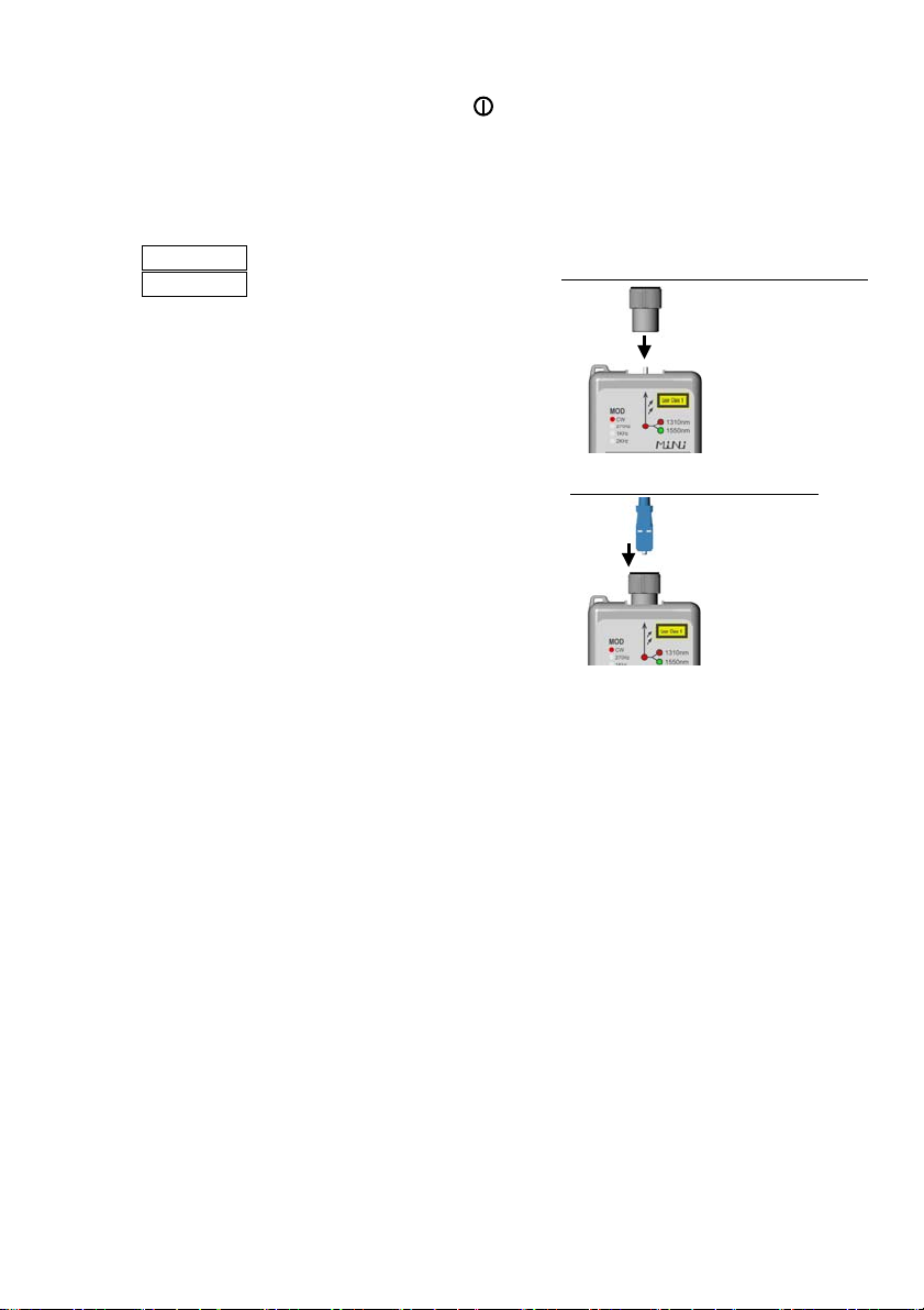
(6). Connect the connector adapter
Tightly attach the connector adapter to the
output port.
(7). Connect the optical fiber
Attach the optical fiber connector to the
connector adapter.
Tighten the connectors securely.
The ferrule face should be kept in a clean
environment away from dust at all times.
3-3. Battery replacement
The blinking of the Power Display LED indicates that the battery is low and needs
replacing.
4. Cleaning the output port
Because the path traveled by light, at the PC polished output port, is extremely
small, any dust on the ferrule face not only disrupts connection with the fiber, but
also leads to greater coupling loss and reflection. Dust can also damage the ferrule.
The output ports are cleaned as follows.
【When the connector adapter is attached 】
a. Remove dust from the ferrule face with a 2.5 mm CLETOP stick or
comparable product.
【When the connector adapter is removed 】
a. Wipe the ferrule face with a swab dipped in ethanol or isopropanol.
b. Wipe the ferrule face with a dry swab once again.
c. Blow on the ferrule face with clean air.
Optical fiber connector
Connector adapter
(7). Connect the optical fiber
Output port
Connector adapter
(6). Connect the connector adapter