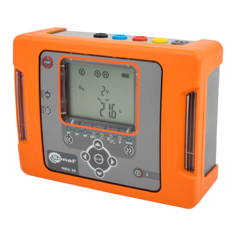
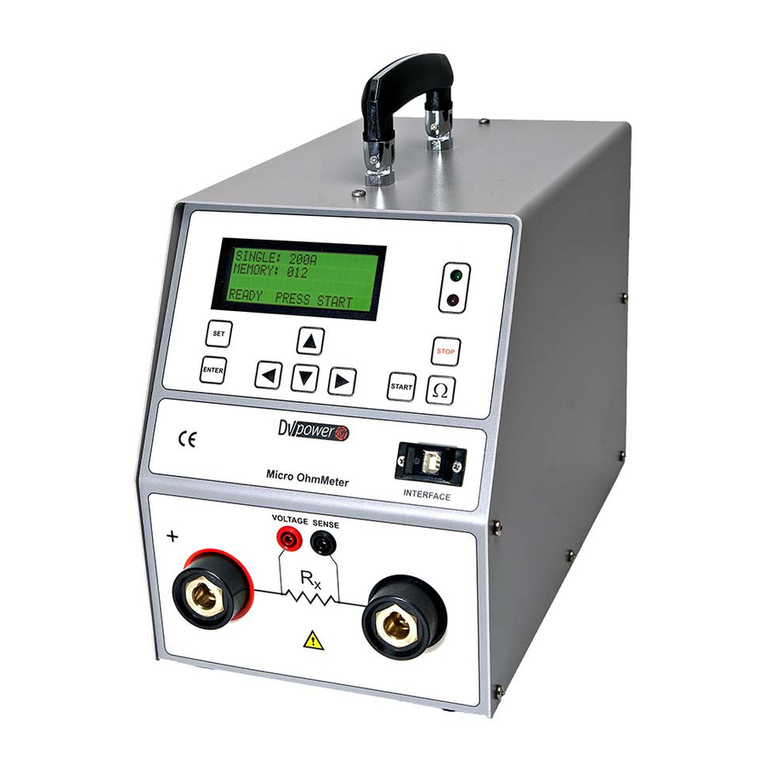
Sonel MRU-30 User manual


MRU-30 –USER MANUAL
2

USER MANUAL
EARTH GROUND RESISTANCE METER
MRU-30
SONEL S. A.
Świdnica, Poland
SONEL TEST & MEASUREMENT
Santa Clara, CA 95054
Version 1.05 26.07.2021

MRU-30 –USER MANUAL
2
The Sonel MRU-30 meter is an easy-to-use instrument that is designed for the safe measurement of
earth ground resistance.
The MRU-30 uses established methods of earth ground resistance measurements such as 3-pole, 4-
pole, and 3-pole with auxiliary clamp. Additionally the MRU-30 employs the two clamp method of
measurement without the use of auxiliary test rods when rods can't be used in some situations.
MRU-30 measurements include: soil resistivity, continuity measurement of protective and equipotential
conductors, leakage currents, and interference voltages.
An integral screen clearly displays results. For safety, and to ensure successful studies, software will
alert the user of possible dangers and irregularities.
The MRU-30 is highly portable, and engineered with a lightweight and compact case. The enclosure
is robust andweatherproof (IP65)to prevent ingress of dust andmoisture, makingit idealfor all outdoor
field work.
It contains a built-in rechargeable battery that can be recharged from a power adapter, or from a stand-
ard 12V vehicle socket.
Please acquaint yourself with this manual to avoid measuring errors and prevent possible problems
related to operation of the meter.
This device complies with part 15 of the FCC Rules. Operation is subject to the following two
conditions: (1) This device may not cause harmful interference, and (2) this device must accept
any interference received, including interference that may cause undesired operation.
This equipment has been tested and found to comply with the limits for a Class B digital device,
pursuant to part 15 of the FCC Rules. These limits are designed to provide reasonable protection
against harmful interference in a residential installation. This equipment generates, uses and
can radiate radio frequencyenergyand, if not installed and used in accordance with the instruc-
tions, may cause harmful interference to radio communications. However, there is no guarantee
that interference will not occur in a particular installation. If this equipment does cause harmful
interference to radio or television reception, which can be determined by turning the equipment
off and on, the user is encouraged to try to correct the interference by one or more of the fol-
lowing measures:
- Reorient or relocate the receiving antenna.
- Increase the separation between the equipment and receiver.
- Connect the equipment into an outlet on a circuit different from that to which the receiver is
connected.
- Consult the dealer or an experienced radio/TV technician for help.
CAUTION:
Equipment changes or modifications not expressly approved by SONEL TEST &
MEASUREMENT Inc., the party responsible for FCC compliance, could void the user’s author-
ity to operate the equipment, and could create a hazardous condition.

MRU-30 –USER MANUAL
3
TABLE OF CONTENTS
1Safety ................................................................................................................5
2Turning the meter ON and activating the screen backlight. .......................6
3Meter configuration .........................................................................................6
4Measurements..................................................................................................9
4.1 Measurement of AC+DC interfering (noise) voltages...............................................9
4.2Earth resistance measurement with 2-pole method (RE2P) ................................... 10
4.3 Earth resistance measurement with 3-pole method (RE3P) ................................... 11
4.4 Earth resistance measurement with 4-wire method (RE4P..................................... 15
4.5 Earth resistance measurement with 3-pole method with additional clamp (RE3P+C)... 18
4.6 Earth resistance measurement with two-clamp method (2C)................................. 22
4.7 Calibration of the measurement clamp C-3............................................................ 24
4.8 Measurement of resistance of protective conductors and equipotential bonding
(RCONT) ................................................................................................................... 26
4.9 Calibration of the test leads for RCONT measurement ............................................. 28
4.10 Earth resistivity measurement (ρ)........................................................................... 29
5Memory of measurement results .................................................................33
5.1 Storing the measurement results in the memory.................................................... 33
5.2 Viewing memory data............................................................................................. 35
5.3 Deleting memory data............................................................................................ 36
5.3.1 Deleting cell data .........................................................................................................36
5.3.2 Deleting bank data.......................................................................................................37
5.3.3 Deleting the whole memory..........................................................................................39
6Data transmission..........................................................................................40
6.1 Computer connection accessories......................................................................... 40
6.2 Data transmission through USB port...................................................................... 40
7Firmware update ............................................................................................41
8Power supply of the meter............................................................................41
8.1 Monitoring the power supply voltage...................................................................... 41
8.2 Charging the rechargeable battery pack ................................................................ 42
8.3 General principles of using Ni-MH batteries........................................................... 43
9Cleaning and maintenance ...........................................................................43
10 Storage............................................................................................................43
11 Dismantling and disposal .............................................................................44
12 Technical specifications ...............................................................................44
12.1 Basic data .............................................................................................................. 44
12.2 Additional data ....................................................................................................... 47
12.2.1 Influence of the serial interference voltage UZon earth resistance measurements for
methods RE3P, RE4P, RE3P+C, ρ.................................................................................47
12.2.2 Influence of the auxiliary electrodes on earth resistance measurements for methods
RE3P, RE4P, RE3P+C, ρ...............................................................................................47

MRU-30 –USER MANUAL
4
12.2.3 Influence of the interference current IZon the result of the earth resistance for method
RE3P+C....................................................................................................................... 47
12.2.4 Influence of interference current on the result of the earth resistance measurement for
two-clamp method (2C)...............................................................................................48
12.2.5 Influence of the relation of the resistance measured with clamp for the multiple earthing
branch to the resultant resistance (RE3P+C)................................................................48
12.2.6 Additional uncertainties in accordance with IEC 61557-5 (RE3P, RE4P).......................48
13 Accessories ................................................................................................... 49
13.1 Standard accessories.............................................................................................49
13.2 Optional accessories ..............................................................................................49
14 Manufacturer.................................................................................................. 50
15 Laboratory services ...................................................................................... 51

MRU-30 –USER MANUAL
5
1 Safety
Electrical safety depends on the correct design and function of earth/ground systems. The MRU-
30 meter has been designed to measure earth/ground installations. For correct operation and correct
results, understand and follow these recommendations:
Before you proceed to operate the meter acquaint yourself thoroughly with this manual and observe
all safety regulations.
The MRU-30 meter has been designed for measurements of earth/ground connections, equipoten-
tial bonding, and ground resistivity. Any application or use of the MRU-30 that differs from those
specified in this manual may result in damage to the meter and constitute a source of danger to the
user.
The device must be operated by appropriately qualified personnel with relevant certification to carry
out measurements of electric installations. Operation of the meter by unauthorized personnel may
result in damage to the device and constitute a source of danger to the user.
Using this manual does not exclude the need to comply with occupational health and safety regu-
lations and other relevant fire regulations required during the execution of a particular type of work.
Before starting work with the device in special environments, e.g. those with potential fire-risk or
explosive environments, consult with the individual responsible for health and safety.
Do not operate the meter in the following situations:
A meter that is damaged or completely or partially malfunctioning.
A meter with damaged test leads or insulation.
A meter stored for long periods in unfavorable conditions (e.g. excessive humidity or tempera-
ture extremes). If the meter is transferred from a cold to a warm environment with a high
level of relative humidity internal condensation can occur. Do not operate until the meter
has reached the new ambient temperature (approximately 30 minutes).
Before operation make sure the test leads are securely connected to the appropriate measurement
sockets.
Do not power the meter from sources other than those described in this manual.
The meter’s inputs are electronically protected from power surges in case of accidental connection
to live conductors: up to 276 V for 30 seconds.
Manufacturer’s calibration does not include test leads resistance. The displayed result is the sum
of the measured object and the test leads resistance. The procedure for calibrating for test lead
resistance is described in section 4.9.
The device complies with the following standards: EN 61010-1 and EN 61557-1, -4, -5.
Note:
Due to continuous development the manufacturer reserves the right to change appearance,
the accessories, and technical parameters of the meter. The display, in case of some of the
functions, may also slightly differ from the display presented in this manual.

MRU-30 –USER MANUAL
6
2 Turning the meter ON and activating the screen backlight.
Turn on the meter with the button.
Short press the button to turn the
screen backlight on; press the button
again to turn the backlight off.
Switch off the meter by pressing and
and holding the button for approx.
2 sec.
Emer-
gency si-
tuations.
Pressing the button for approx. 7
seconds will turn off the meter in case
of emergency.
3 Meter configuration
Turn on the meter by pressing the
button and the SET/SEL button simulta-
neously.
When the Fn screen is displayed use the
and buttons to set the local mains
frequency –50 Hz or 60 Hz (50 Hz is set
as default).

MRU-30 –USER MANUAL
7
Use the and buttons to show bEEP
on the screen to allow turning audio sound
on or off.
Use the and buttons to turn the au-
dio sound ON ( ) or OFF ( ).
Press the and buttons to show the
oFF screen to allow the setting of the
auto-power off time (Auto-OFF):
Use the and buttons to set the
time to turn the meter off automatically
(Auto-OFF): The choices are 300 s, 600 s,
900 s or none (dashes - Auto-OFF is disa-
bled).

MRU-30 –USER MANUAL
8
Use the and buttons to show the
diSt screen to allow the unit of length to be
selected:
Use the and buttons to set the unit
of length: ‘m’(meters) or ‘ft’(feet) (‘m’is
set as default).
Use and buttons to show the UPdt
screen to install new firmware updates.
Press ENTER to enter firmware update mode.
The update process is described in section 7.
After changing the parameters, to exit the SETUP menu, either:
Press the ENTER button to memorize set-
tings (not applicable for the Update screen)
Or: press the ESC button to go to the meas-
urement screen without confirming changes.

MRU-30 –USER MANUAL
9
4 Measurements
Note:
During measurements the status bar is displayed.
4.1 Measurement of AC+DC interfering (noise) voltages
Note:
This measurement is active only when the meter is set for the following measure-
ments, before starting them with the START button: RE2P, RE3P, RE4P, RE3P+C,
RCONT, ρ.
Before starting the measurement in these modes: RE2P, RE3P, RE4P, RE3P+C, RCONT
and ρ, and before pressing the START button the MRU-30 monitors the voltage pre-
sent on the measurement terminals (between Eand other sockets) and displays the
value of the interfering voltage on the screen.
Additional information displayed by the meter
VN>100V,>100V and
a continuous tone ,
‘NOISE!’and
The voltage on the measurement terminals is > 100 V.
The measurement cannot proceed.
VNxxV,>40V and a
continuous tone ,
‘NOISE!’and
Where xx is the value of the interfering voltage. The volt-
age on the measurement terminals is > 40 V. The meas-
urement cannot proceed.
VNxxV,>24V,
‘NOISE!’and
Where xx is the value of the interfering voltage. The volt-
age on the measurement terminals is > 24 V, but < 40 V.
The measurement cannot proceed.
‘NOISE!’
The value of the interfering voltage is < 24 V, but has a
high value. Results may be affected by additional uncer-
tainty.

MRU-30 –USER MANUAL
10
4.2 Earth resistance measurement with 2-pole method (RE2P)
Use the << or >> buttons to select the measurement
mode: 2P. The LED is illuminated. The meter is
now in the state of measuring interfering noise volt-
age between the measurement terminals.
Press the SET/SEL button to select the measurement
voltage.
Use the and buttons to set the measurement
voltage value to 25 V
or 50 V.
or
Press ENTER to save the setting or press
ESC to exit without saving.
The meter is ready for
measurement.
Press START to begin measurement.
Connect the test leads according to the drawing.

MRU-30 –USER MANUAL
11
After the measurement
completes view the results
on the screen.
The result is displayed for 20 seconds. Press ENTER to display again.
Additional information displayed by the meter
VN>100V,>100V and
a continuous tone ,
‘NOISE!’ and
The voltage on the measurement terminals is > 100 V.
The measurement cannot proceed.
VNxxV, >40V and a
continuous tone ,
‘NOISE!’ and
Where xx is the value of the interfering voltage. The volt-
age on the measurement terminals is > 40 V. The meas-
urement cannot proceed.
VNxxV,>24V,
‘NOISE!’ and
Where xx is the value of the interfering voltage. The volt-
age on the measurement terminals is > 24 V, but < 40 V.
The measurement cannot proceed.
‘NOISE!’
The value of the interfering voltage is < 24 V, but has a
high value. Results may be affected by additional uncer-
tainty.
4.3 Earth resistance measurement with 3-pole method (RE3P)
The basic type of earth ground resistance measurement is the 3-pole measurement.
Disconnect the earth electrode object of test.

MRU-30 –USER MANUAL
12
Use the << or >> buttons to select the
measurement mode: 3P.The LED is
illuminated. The meter is now in the state of
measuring the interfering noise voltage
seen on the measurement terminals.
Press the SET/SEL button to select the
measurement voltage.
Use the and button to set the meas-
urement voltage value to 25 V or 50 V.
or
Press ENTER to save the setting or
press ESC to exit without saving.
Drive the current electrode into the ground and connect it to the Hterminal of the
meter.
Drive the voltage electrode into the ground and connect it to the Sterminal of the
meter.
Connect the earth electrode object of test to the Eterminal of the meter.
All 3 electrodes should be aligned in a straight line.
The meter is ready for
measurement.
Connect the test leads according to this diagram:

MRU-30 –USER MANUAL
13
Press START to begin measurement.
After the measurement
completes view the results
on the screen.
Use the and buttons to toggle between
the measurement results:
RH –resistance of current electrode
RS - resistance of voltage electrode
ER –additional uncertainty caused by the re-
sistance of the auxiliary electrodes
VN –interfering (noise) voltage
The result is displayed for 20 seconds. Press ENTER to display again.
S
Repeat the test two or more times by moving the
voltage electrode a couple of meters or yards, alter-
nately towards and away from the earth electrode
object of test (E) and repeat steps 7, 8 and 9.
If the REtest results differ bymore than 3% it is nec-
essary to significantly increase the distance be-
tween the current electrode and the earth electrode
object of test (E) and repeat the measurements.
Note:
Earth resistance measurements are usually good if the interference voltage is
< 24 V. The meter can measure in the presence of interference voltage up to
100 V. Over 40 V it is indicated as hazardous. Do not connect the meter to a volt-
age exceeding 100 V.
Pay attention to the quality of the connection to the electrode object of test with the test
leads –the contact area must be cleaned of paint, rust, corrosion etc.
If the resistance of the auxiliary electrodes is too high, then the measurement of the REearth
electrode will be distorted by additional uncertainty. A particularly high measurement
uncertainty is generated if we measure a low value of the earth resistance with electrodes of
a loose contact with the soil (such a situation occurs often if the earth electrode is properly
made and the upper layer of the ground is dry and characterized by alow conductivity). Then
the relation between the electrode resistance and the resistance of the measured earthing is

MRU-30 –USER MANUAL
14
very high, andso is the case of the measurement uncertainty which depends on it. Whatmay
be done then is to perform, in accordance with the formulae specified in point 12.2,
calculations, which will permit to evaluate the influence of the measurement conditions. It is
also possible to improve the contact of the electrode with the ground, for example by means
of moistening of the place when the electrode is driven, its driving into the ground in another
place or using a 80 cm electrode. Check also the test leads and make sure the insulation is
not damaged and the contacts: test lead –banana plug –electrode are not corroded or
loosened. In most cases the achieved resolution of the measurement is sufficient, but it is
necessary to be conscious of the uncertainty the measurement is burdened with.
Additional information displayed by the meter
RE>9999Ω
Measurement range exceeded.
VN>100V,>100V
and a continuous
tone , ‘NOISE!’
and
The voltage on the measurement terminals is > 100 V.
The measurement cannot proceed.
VNxxV,>40V and a
continuous tone ,
‘NOISE!’ and
Where xx is the value of the interfering voltage. The volt-
age on the measurement terminals is > 40 V. The meas-
urement cannot proceed.
VNxxV, >24V,
‘NOISE!’ and
Where xx is the value of the interfering voltage. The volt-
age on the measurement terminals is > 24 V, but < 40 V.
The measurement cannot proceed.
‘NOISE!’
The value of the interfering voltage is < 24 V, but has a
high value. Results may be affected by additional uncer-
tainty.
and ER along with %
value
The uncertainty caused by resistance of the electrodes is >
30%. (Uncertainties calculated on the basis of the meas-
ured values.)
and RHor RSalong
with Ωvalue
The resistance of H and S electrodes, or one of them ex-
ceeds 19.9 kΩ. The measurement is subject to error.
Flashing symbols:
, ,
Flashing symbols E, H, S, indicate a test lead is discon-
nected from the measurement terminals.

MRU-30 –USER MANUAL
15
4.4 Earth resistance measurement with 4-wire method (RE4P
The 4-wire method is recommended in the case of measurements of earth ground resistance of
very low values. It eliminates the influence of the test lead resistances. To evaluate the resistivity of the
ground it is recommended to use the dedicated measurement function in section 4.9.
Disconnect the earth electrode object of test.
Use the << or >> buttons to select the
measurement mode: 4P. The LED is
illuminated. The meter is now in the state of
measuring interfering noise voltage be-
tween the measurement terminals.
Press the SET/SEL button to select the
measurement voltage.
Use the and buttons to select the
measurement voltage of 25 V or 50 V.
or
Press ENTER to save the setting or
press ESC to exit without saving.
Drive the current electrode into the ground and connect it to the Hterminal of the meter.
Drive the voltage electrode into the ground and connect it to the Sterminal of the meter,
Connect the earth electrode object of test to the Eterminal of the meter.
Connect the ES terminal to the earth electrode object of test below the E connection.
All 3 electrodes should be aligned in a straight line.
Connect the test leads according to this diagram:

MRU-30 –USER MANUAL
16
The meter is ready for
measurement.
Press START to begin measurement.
After the measurement
completes view the results
on the screen.
Use the and buttons to toggle between
the measurement results:
RH –resistance of current electrode
RS - resistance of voltage electrode
ER –additional uncertainty caused by the re-
sistance of the electrodes
VN –interfering (noise) voltage.
The result is displayed for 20 seconds. Press ENTER to display again.
S
Repeat the test two or more times by moving the
voltage electrode a couple of meters or yards, alter-
nately towards and away from the earth electrode
object of test (E) and repeat steps 7, 8 and 9.
If the REtest results differ by more than 3% it is
necessary to significantly increase the distance be-
tween the current electrode and the earth elec-
trode object of test (E) and repeat the measure-
ments.

MRU-30 –USER MANUAL
17
Note:
Earth resistance measurements are usually good if the interference voltage is
< 24 V. The meter can measure in the presence of interference voltage up to
100 V. Over 40 V it is indicated as hazardous. Do not connect the meter to a volt-
age exceeding 100 V.
Pay attention to the quality of the connection to the electrode object of test with the test
leads –the contact area must be cleaned of paint, rust, corrosion etc.
If the resistance of the auxiliary electrodes is too high, then the measurement of the REearth
electrode will be distorted by additional uncertainty. A particularly high measurement
uncertainty is generated if we measure a low value of the earth resistance with electrodes of
a loose contact with the soil (such a situation occurs often if the earth electrode is properly
made and the upper layer of the ground is dry and characterized by alow conductivity). Then
the relation between the electrode resistance and the resistance of the measured earthing is
very high, andso is the case of the measurement uncertainty which depends on it. Whatmay
be done then is to perform, in accordance with the formulae specified in point 12.2,
calculations, which will permit to evaluate the influence of the measurement conditions. It is
also possible to improve the contact of the electrode with the ground, for example by means
of moistening of the place when the electrode is driven, its driving into the ground in another
place or using a 80 cm electrode. Check also the test leads and make sure the insulation is
not damaged and the contacts: test lead –banana plug –electrode are not corroded or
loosened. In most cases the achieved resolution of the measurement is sufficient, but it is
necessary to be conscious of the uncertainty the measurement is burdened with.
Additional information displayed by the meter
RE>9999Ω
Measurement range exceeded.
VN>100V,>100V and a continuous
tone , ‘NOISE!’ and
The voltage on the measurement terminals is > 100 V.
The measurement cannot proceed.
VNxxV,>40V and a continuous tone
, ‘NOISE!’ and
Where xx is the value of the interfering voltage. The volt-
age on the measurement terminals is > 40 V. The meas-
urement cannot proceed.
VNxxV,>24V,‘NOISE!’ and
Where xx is the value of the interfering voltage. The volt-
age on the measurement terminals is > 24 V, but < 40 V.
The measurement cannot proceed.
‘NOISE!’
The value of the interfering voltage is < 24 V, but has a
high value. Results may be affected by additional uncer-
tainty.
and ER along with % value
The uncertainty caused by resistance of the electrodes is >
30%. (Uncertainties calculated on the basis of the meas-
ured values.)
and RHor RSalong with Ωvalue
The resistance of H and S electrodes, or one of them ex-
ceeds 19.9 kΩ. The measurement is subject to error.
Flashing symbols:
, , ,
Flashing symbols E, Es, H, S, indicate a test lead is dis-
connected from the measurement terminals.

MRU-30 –USER MANUAL
18
4.5 Earth resistance measurement with 3-pole method with additional
clamp (RE3P+C)
Use the << or >> buttons to select the
measurement mode: 3P+ . The LED
is illuminated. The meter is now in
the state of measuring interfering noise volt-
age between the measurement terminals.
Press the SET/SEL button to select the
measurement voltage.
Use the and buttons to set the
measurement voltage value to 25 V or 50
V.
or
Press ENTER to save the setting or
press ESC to exit without saving.
Drive the current electrode into the ground and connect it to the Hterminal of the meter.
Drive the voltage electrode into the ground and connect it to the Sterminal of the meter,
Connect the earth electrode object of test to the Eterminal of the meter.
Attach the receiving clamp around the earth electrode object of test below the Ecable
connection.
All 3 electrodes should be aligned in a straight line.
Connect test leads according to this diagram:
Other manuals for MRU-30
3
Table of contents
Other Sonel Measuring Instrument manuals
Sonel
Sonel MPI-525 User manual
Sonel
Sonel MIC-10 User manual
Sonel
Sonel LMW-100 User manual
Sonel
Sonel CMP-2000 User manual
Sonel
Sonel PAT-1 User manual

Sonel
Sonel MMR-640 User manual

Sonel
Sonel MRU-120HD User manual

Sonel
Sonel CMP-1010 User manual

Sonel
Sonel TDR-420 User manual

Sonel
Sonel BT-120 User manual
Sonel
Sonel CMP-3000 User manual

Sonel
Sonel KT-800M User manual

Sonel
Sonel PQM-701 User manual

Sonel
Sonel PQM-700 User manual
Sonel
Sonel WMGBMZC304F User manual
Sonel
Sonel IRM-1 User manual
Sonel
Sonel MIC-05s1 User manual
Sonel
Sonel MRU-21 User manual
Sonel
Sonel MPI-540 User manual
Sonel
Sonel LXP-1 User manual
