Great Outdoors A05714W User manual

Great Outdoors
the ®
Do not store or use gasoline or other
flammable vapors and liquids in the
vicinity of this or any other appliance.
An unconnected liquid propane
cylinder should not be stored in the
vicinity of this or any other appliance.
If you smell gas:
Shut off gas to the appliance.
Extinguish any open flame.
Open lid.
If odor continues, immediately call
your gas supplier or fire department.
Read all of these instructions and keep them in a safe place for future reference.
Leave these instructions with the consumer.
Assembly and
Owner’s Manual
FOR YOUR SAFETY: Never leave a grill unattended when in use.
FOR YOUR SAFETY
1
2
1
2
3
4
CONSUMER / USER:
ASSEMBLER / INSTALLER:
FOR YOUR SAFETY
A05714W
X-Series
Portable
Gas Grill
L.P. Gas
Cylinder
Not Included

4
4
4
5-7
8
10
11
12
13
14
15
16
17-18
19
20
21
22
23-24
9
Table of Contents
Chapte r 1 - INSTALLATION
Necessary Information . . . . . . . . . . . . . . . . . . . . . . . . . . .
Choosing a Safe Location . . . . . . . . . . . . . . . . . . . . . . . . .
PortableL.P.GasGrills ...........................
L.P. Gas Dealer Instructions . . . . . . . . . . . . . . . . . . . . . . .
Step 1 ( Identifying Parts ) . . . . . . . . . . . . . . . . . . . . . . . . .
Step2(AttachLegs) ............................
Step3(AttachFeet)............................
Step4(TankRetainer) ..........................
Step5(ModestyPanel) ..........................
Step6(SideTables) ............................
Step7(GrillHead) ..............................
Step 8 ( Sideburner Hose ) . . . . . . . . . . . . . . . . . . . . . . . .
Step9(LidHandle) .............................
Step10(InternalParts) ..........................
Step11(WarmingRack) .........................
Step12(DripCup) ..............................
Installing an L.P. Gas Cylinder . . . . . . . . . . . . . . . . . . . . .
Chapter 2 - ASSEMBLY INSTRUCTIONS
Page Number
CFM Corporation
2695 Meadowvale Boulevard
Mississauga, Ontario L5N 8A3 Canada
(800) 668-5323
www.cfmcorp.com
Service Note: If you are experiencing difficulties or are dissatisfied with your purchase, please contact CFM at
the telephone number listed above prior to returning your grill to the store.
®
Formerly:
Now:

4
·
·
·
·
·
Operating this or any gas-fired appliance
in an enclosed area can produce a build-up
of carbon-monoxide, which could result in
injury or death.
or, in the absence of local codes, with
either the National Fuel Gas Code, ANSI
Z223.1, NFPA 54 (USA), or CAN/CGA-B
149.2, Propane Installation Code (Canada)
and CAN/CGA-B 149.1 Natural Gas
Installation Code.
To check local codes, contact your local gas
dealer or gas company listed in the Yellow
Pages for recommended installation
procedures and regulations.
Do not use a grill under a ceiling or cover
where the heat or flame could cause
damage.
Choose a level surface where the grill is
not facing directly into the wind.
Avoid moving the grill during use.
Do not use lighter fluid or charcoal
briquettes in a gas grill. The flow of
combustion and ventilation air is not to be
obstructed. The ventilation openings of the
cylinder enclosure must be kept free and
clear from other debris. Do not store grill
covers or other items in the cylinder area.
·Do not operate this barbecue in garages,
breeze ways, sheds or any enclosed area.
Choosing a Safe Location
for a Gas Barbecue Grill
Necessary Information to
Safely Use a Gas Grill
Installation 1Chapter
X-Frame Model Series Gas Grill
The gas fuel used by this product is
highly flammable and must be used in
a responsible and cautious manner.
It is your responsibility to assemble,
operate, and maintain your gas
barbecue grill properly.
If these instructions are ignored, there
is a possibility of a hazardous fire or
explosion which could result in proper-
ty damage, physical injury or death.
2. Installation must conform with local
codes
3. This appliance is not intended to be
installed in or on a recreational vehicle
and/or boat.
4. Keep the barbecue grill at least 24
inches (61 cm) away from any combustible
construction.
5. The grill area must be clear and free from
combustible materials, gasoline, and any
other flammable liquids or vapors.
1. The gas barbecue grill may only be used
for cooking out-of-doors.

5
The L.P. Fuel Supply System
Hot drippings from cooking food could
damage the fuel supply system.
Liquid Propane (abbreviated L.P.) gas is
stored under high pressure inside a cylinder
and will vaporize when released. It is
important that there are no leaky connections
on the grill fuel supply system. Refer to the
Leak Testing section of this manual.
An L.P. gas grill requires a fuel delivery
system made up of a L.P. gas supply
cylinder, a fuel regulator with hose and a
gas-control valve.
·
L.P. Gas
The L.P. Fuel Supply System
Do not store an L.P. cylinder in a building,
garage or any other enclosed area. Instead,
store the cylinder outdoors in a well
ventilated area, away from people and out of
the reach of children.
Place your barbecue grill in a location
away from children and pets.
Do not leave grill unattended when in use.
To avoid burns, do not touch any hot grill
surface. If necessary, use a protective glove
when operating control knobs, tank shut-off
valve, or lid handle.
Do not place combustible material, such
as cloth or plastic, on grill surface during
use.
Do not lean on side tables or place more
than 15 pounds of weight on a side table.
·
·
·
·
·
Portable L.P. Gas
Barbecue Grills
9. Make sure that the drip pan is in place
under the grill bottom.
Do not use natural gas in an
appliance designed for L.P. gas. Use only
liquid propane (L.P.) gas in an appliance
designed for L.P. gas.
NEVER leave a grill
unattended when in use.
IMPORTANT:
WARNING:
6. Do Not store a spare L.P. gas cylinder
under or near this appliance.
7. NOT FOR USE BY CHILDREN.
8. The outside of the barbecue grill will
become hot during use.

6
4. The pressure regulator and hose
assembly provided is factory set at an outlet
pressure of 11 inches water column (.4 lb.
per sq. Inch).
L.P. Cylinders can be obtained at the store
where you purchased your grill or from an
authorized L.P. gas dealer.
Any L.P. gas-supply cylinder used with this
grill must be approximately 12 inches
diameter and 18 inches high.
L.P. GAS SUPPLY CYLINDER
L.P. GAS CYLINDER SPECIFICATIONS
The maximum
fuel capacity must be 20 pounds of propane.
Full-cylinder weight should be approximately
38 pounds (43.7 lbs. Nominal water
capacity).
FUEL REGULATOR AND HOSE
The fuel regulator supplied is equipped with
a Type 1 coupling nut. Do not attempt to
connect to any other L.P. cylinder not
equipped with a mating Type 1 cylinder
valve. This grill is not to be used with any
other cylinder connection device.
The fuel regulator and hose assembly with
the Type 1 fitting supplied must be used with
the appliance. Do not use a hose and
regulator assembly other than the one
supplied with the grill or a manufacturer’s
replacement fuel pressure regulator
assembly.
The Type 1 connection system has the
following features:
1. The system will not allow gas to flow until
a positive connection has been made.
2. The system has a thermal element that
will shut off the flow of gas between 240°F
and 300°F.
3. The system has a flow-limiting device
which, when activated, will limit the flow of
gas to 10 cubic feet per hour.
The L.P. Fuel Supply System
(the fuel regulator and hose)
Fuel Supply
Hose
Valve
Orifice
Type 1 Fuel
Regulator
Dual Burner
Fuel-Control Valve
The L.P. Fuel Supply System
(L.P. gas cylinder)
L.P. Gas
Cylinder
Cylinder Control
Valve
Any attempt to adjust the
regulator is dangerous and could create a
situation causing personal injury or property
damage. Consult your L.P. gas dealer if you
think the regulator is not working properly.
WARNING:
NOTE:
L.P. Gas
Cylinder
NOT
INCLUDED

7
Have the gas dealer weigh the cylinder
after filling to ensure that the cylinder is not
overfilled.
TRANSPORTING A FULL CYLINDER
You should transport only one cylinder at a
time. Transport the cylinder in an upright and
secure manner with the control valve turned
off and the POL dust cap in place.
Do not transport a cylinder in the passenger
compartment of a vehicle.
Do not leave cylinder in direct sunlight or in
a high-heat area such as a closed car trunk.
High-heat areas could cause the relief valve
to vent gas.
Use a cylinder cap on the cylinder-valve
outlet during transport and when the cylinder
is not connected to the grill. Keep cylinder
valve closed when not in use.
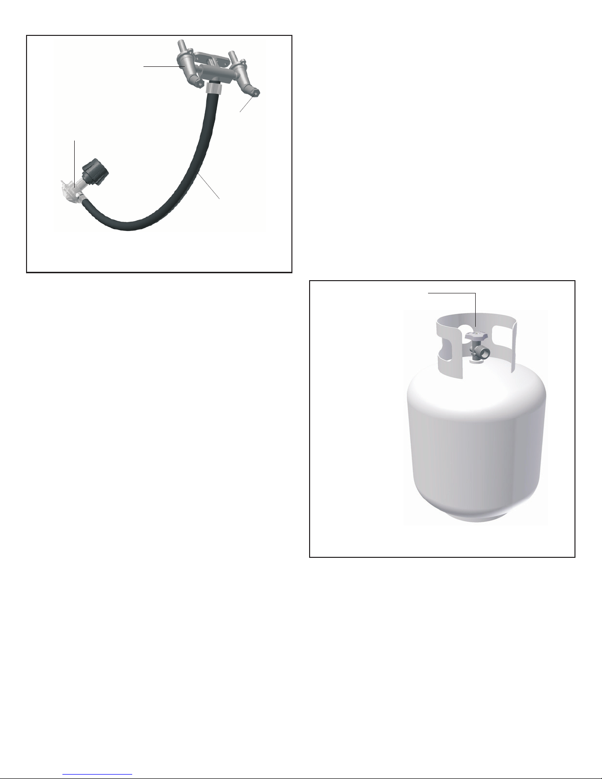
The L.P. gas cylinder must have a shut-off
valve
A Type 1 compatible
cylinder with a Type 1 cylinder valve has a
positive seating connection that does not
permit gas flow until a positive seal has been
obtained.
The cylinder must be arranged for vapor
withdrawal. It must also include a collar to
protect the cylinder valve. A safety-relief
device having direct communication with the
vapor space of cylinder must be provided.
This will expel high-pressure gas if the
cylinder is overfilled or overheated.
All L.P. gas cylinders used with this
appliance shall be constructed and marked
in accordance with the specifications for L.P.
gas cylinders of the U.S. Department of
Transportation (DOT) or the National
Standard of Canada, CAN/CSA-B339,
Cylinders, Spheres and Tubes for
Transportation of Dangerous Goods; and
Commission, as applicable; and shall be
provided with a listed overfilling-prevention
device. Read labels on the L.P. gas-supply
cylinder.
Inform the gas dealer if it is a new or used
cylinder to be filled. Caution the gas dealer
not to overfill the fuel cylinder.
After filling, have the gas dealer check for
leaks and that the relief valve remains free to
function.
Allow only a qualified L.P. gas dealer to
fill or repair an L.P. gas-supply cylinder.
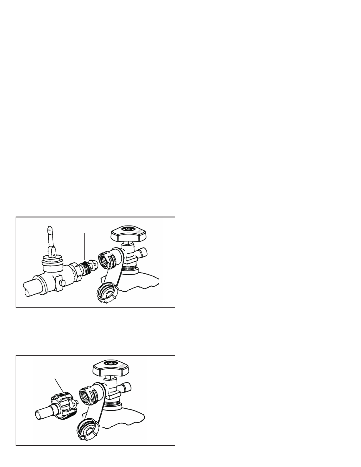
terminating in a Type 1 L.P. gas-
cylinder-valve outlet.
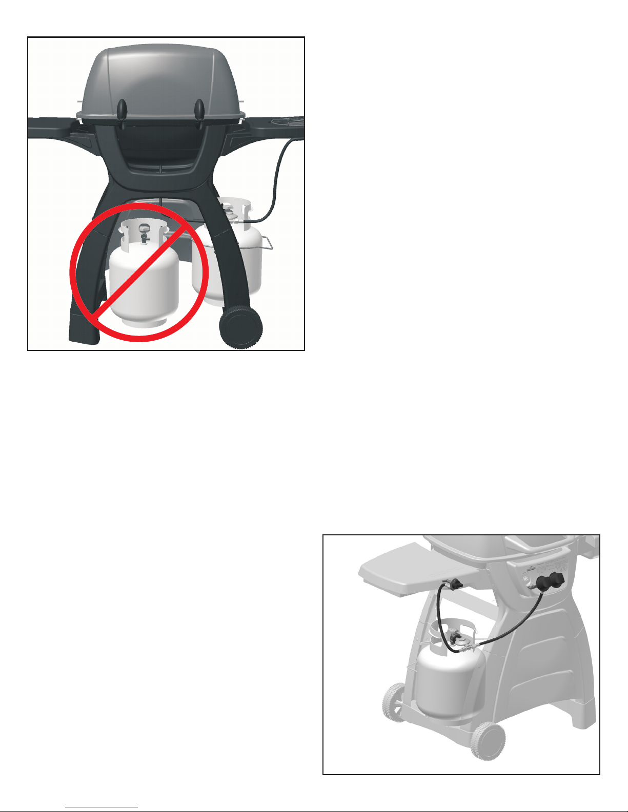
a.) Do not store a spare L.P. gas cylinder
under or near this appliance.
b.) Never fill the gas cylinder beyond 80
percent full.
c.) If the information in (a.) and (b.) Is not
followed exactly, a fire causing serious
injury or death may occur.
Handle a full cylinder with care.
Gas is under high pressure.
DANGER:
WARNING:
Do not insert any foreign objects
into the valve outlet. You may damage the
back check, A damaged back check can
cause a leak, which could result in explosion,
fire, severe personal injury or death.
DANGER:

8
The L.P. gas cylinder has a Type 1 cylinder
valve with a back-check module in its outlet
that will not permit gas to flow until an
evacuation device is installed. To purge the
L.P. gas cylinder, the back-check module must
be opened with an evacuation device.
A. Hose-end valve with a bleed port: Purging
can be accomplished using a hose-end valve
containing a bleed port, which also allows for
evacuation without the use of an adapter.
B. Hose-end valve without a bleed port:
When a hose-end valve does not have a bleed
port, a separate device must be used for
evacuation.
C. Purging using a Type 1 connection: L.P.
gas cylinder evacuation can be accomplished
during each purging by using a Type 1
connection. The Type 1 valve outlet has 1-
5/16” external ACME right-hand thread that will
accept this connection.
After purging or filling an L.P. gas
cylinder, do not insert a POL plug into the
valve outlet. Insertion of this plug will prevent
the back-check from closing. Use ONLY the
provided cap and strap attached to the outlet.
Close the cylinder valve knob before returning
the cylinder to the customer.
For proper purging procedures in the USA,
refer to: Safety Bulletin NPGA # 133, “Purging
L.P. Gas Cylinders,” and Safety Bulletin NPGA
#130, “Recommended Procedures for Filling
Cylinders.”
PURGING AND EVACUATION DEVICES
FOR L.P. GAS CYLINDER WITH TYPE 1
CYLINDER VALVES
CAUTION:
When using a cylinder exchange, be sure the
exchanged cylinder is a Type 1 cylinder; a 510
POL cylinder will not fit a Type 1 regulator.
Purge new cylinders before
filling. This tank is easily filled with a standard
CGA 510 POL filling connection.
FILLING AND PURGING
TYPE 1 L.P. GAS CYLINDERS
IMPORTANT:
Example B
Type 1
(cut away to see fitting)
Filling a Type 1 Cylinder Valve
Example A: shows a CGA-510 POL fitting.
Example B: shows using a Type 1 POL fitting.
Example A
CGA-510 POL
Take These Instructions to the L.P. Gas Dealer
Do not fill an L.P. gas cylinder
beyond 80% full. If this information is not
followed exactly, a fire causing serious injury
or death may occur.
DANGER:
Purging and filling of L.P. gas
cylinders must be performed by personnel who
have been thoroughly trained in accepted L.P.
gas industry procedures. Failure to follow this
instruction may result in explosion, fire, severe
personal injury or death.
DANGER:

9
Getting Started
Unpacking the Grill Parts
Tools needed to assemble grill:
·
·
·
1. Please follow the steps in the order that
they are presented.
2. Assemble the grill where you plan to use
it.
3. You may want to place an old towel or
cloth at the assembly site to prevent nuts
and bolts from becoming lost.
4. Have a friend help. An assistant can
make the assembly easier by holding the
parts in place while you fasten the nuts and
bolts.
5. To be ready to barbecue immediately,
have the L.P. gas cylinder filled by an
authorized L.P. dealer or cylinder exchange
center.
1. Remove and set aside all inner boxes
and parts from the master carton.
2. Remove and set aside all wrapping
paper and additional packaging from the
parts.
3. Do not destroy carton or packing until
your grill is completely assembled and
operating to your satisfaction.
10mm closed-end wrench*
Phillips-head screwdriver
17mm / 7mm open-end wrench*
*
(tools included)
A socket set or an adjustable wrench may be used
in place of the open-end wrenches if desired.
Assembly Instructions 2Chapter
X-Frame Model Series Gas Grill

Right Foot
Left Foot
(Tank Holder)
Modesty
Panel
Rear
X-Frame Storage Bin
Drip Cup
and Holder
Wire
X-Brace
Wire Tank
Retainer
Legs
Legs (with
tank brackets)
Wheel
Axle
Front X-Frame
with Control Panel
Sideburner
Table
Assembly
Side Table
Assembly
Condiment
Basket
Tank
Heat Shield
Heat
Plate
Cooking Grids
Warming Rack
Lid Handle
Handle
Heat Shield
Grill Head
Assembly
10
Not Pictured:
Master Hardware Pack
Locate these parts:
Assembly Step 1 - Identifying the Grill Parts
Note: Refer to the parts
listing on page 32 of the
manual for replacement part
information.

11
1.
2.
3.
4.
Attach the leg to the X-frame by
inserting the top tabs into the
corresponding slots in the X-frame
as shown.
Line up the bolt holes on the side of
each leg and insert a bolt into each
of the bolt holes.
Tighten the bolts securely.
Repeat steps 1 through 3 above for
each leg and frame. Be sure to
match the correct leg component to
its corresponding side, left/right.
When these steps are complete, you
will have 2 sets of frames with legs
attached.
LOCATE THESE PARTS:
2 Right
Legs
2 Left
Legs
X-Frame
X-Frame
with
Control
Panel
M6x15mm
Bolt (8)
M6 Flat
Washer (8)
USE HARDWARE ”A”
Phillips head screwdriver
Tools Needed:
Assembly Step 2 - Attach Legs to X-Frames
A
AB
B

C
D
12
1.
2.
3.
4.
Assemble the wheels and axle to the
tank-side foot as shown above right.
Insert the axle through the foot, one
wheel on each end, tighten one nut
and wheel washer on each end, and
snap the hub caps onto the wheels
Attach each foot to the bottom of
the frame assemblies as shown.
The legs will snap into the feet.
Be sure the is on
the of the assembly as
shown.
For each mounting location,
insert 2 bolts with washers as
shown.
Once all of the bolts are
securely tightened,
position the assembly so
that the wheels are on
your left side as you
face it. (This is the front)
wheeled foot
left side
LOCATE THESE PARTS:
M10 Axle
Nut (2)
B
Wheel
Washer(2)
A
M6x15mm
Bolt (8)
C
M6 Flat
Washer (8)
D
USE HARDWARE ”B”
Left Foot
(tank side)
Hub
Cap
Axle
Nut
Wheel
Washer
B
A
Wheel
Axle
Assembly Step 3 - Attach the Feet
Right Foot
Phillips head screwdriver
17mm Wrench
Tools Needed:
LEFT
FOOT

13
1.
2.
3.
4.
Insert the legs of the wire tank retainer
into the mounting brackets inside the grill
legs. The wire tank retainer must be
mounted on the wheel side of the grill.
Insert the ends of the wire x-brace
into the mounting
holes located
near the
middle of
the grill legs
and thread
a M6 wing
nut onto
each end.
Thread M6
wing nuts onto
the ends of the
wire tank retainer.
Align the center hole of the x-brace wires,
insert the M4 bolt through both wires, and
thread on the M4 wing nut as
shown above right.
Assembly Step 4 - Install the Tank Retainer
Wire
X-Brace
Wire Tank
Retainer
LOCATE THESE PARTS:
M6 Wing
Nut (6)
C
M4x10mm
Bolt (1)
B
M4 Wing
Nut (1)
A
USE HARDWARE ”C”
B
A
C
C
Phillips head screwdriver
Tools Needed:

B
A
14
1.
2.
3.
Position the modesty panel between the front legs of the
assembly. Align the mounting tabs with the bolt holes in
the legs.
From the back side of the assembly, insert the
M4 bolts through each of the mounting holes
and thread on the M4 KEPS nuts.
insert the bolt indicated - it will be installed
during a later assembly step.
Position the Tank Heat Shield
between the front and rear
x-frame assemblies as shown
below.
DO NOT
yet
4.
5.
For each mounting hole, insert M4 bolts and
thread on M4 KEPS nuts.
Securely tighten all the bolts. Remember to set
aside the remaining bolt and nut for a later step.
Assembly Step 5 - Attach the Modesty Panel
Modesty
Panel
Tank
Heat
Shield
LOCATE THESE PARTS:
M4 KEPS
Nut (6)
AM4x15mm
Bolt (6)
B
USE HARDWARE ”D”
Phillips head screwdriver
Tools Needed:
7mm Wrench
A
B
IMPORTANT! The Tank Heat Shield
must be properly installed to provide an
additional precautionary safeguard.

15
1.
2.
3.
Start with the side burner table (left
side). In order to align the table with
the mounting holes, the table bracket
must be maneuvered from above the
assembly and worked into place from
the inside as shown.
For each mounting hole, insert the M6
hex bolts. Insert the bottom bolts first,
then the top bolts as indicated above.
Ensure the table is level, then
securely tighten all of the bolts.
Note: the illustration shows only
the left side table being
attached - repeat the steps
for the right side table.
Assembly Step 6 - Attach the Side Tables
Tools Needed:
Left Sideburner
Table Assembly
Left Sideburner
Table Assembly
Right Side
Table Assembly
LOCATE THESE PARTS:
M6x10mm
Bolt (8)
USE HARDWARE ”E”
10mm Wrench
A
A
1
1
22

20
1.
2.
3.
Set the Heat Plate into the tub as
shown. It will rest on the lowest ledge
inside the tub, just above the burner.
Set the cooking grids into the tub. They
will rest on the topmost ledge of the
tub. There are each a left and right
cooking grid - interchange the grids
left-to-right to determine the best fit.
Open the right side table lid and place
the sidetable storage tub into the
holder.
No tools are required
for this step.
Heat Plate
Cast Iron
Cooking Grids Sidetable
Storage Bin
(Right)
(Left)
Assembly Step 10 - Installing the Grids
LOCATE THESE PARTS:
1
2
3
2

21
3.
4.
Work the other end of the rack into the
other side of the lid.
Insert the other foot of the warming
rack into the other side of the grill tub.
It will require slight bending to place
the foot into the mounting hole.
1.
2.
Position the warming rack as shown and
insert one end of the rack into the lid as
shown.
Working on the same side of the grill,
insert one foot of the warming rack into
the mounting hole near the top of the grill
tub.
No tools are required for this step.
Assembly Step 11 - Install the Warming Rack
LOCATE THESE PARTS:
Warming Rack
Assembly
1
3
2
4

STEP 5. If the burner fails to light properly, turn
the burner control knob off. Also turn off the
L.P. cylinder valve. Wait five minutes before
attempting to light the burner again. This will
allow time for released gas to disperse.
HINT: If the burner does not light after trying
again, turn off burner-control knob, the L.P.
cylinder valve and try match lighting the grill
once the gas has cleared.
Operating the Side Burner
Use the SIDE BURNER gas control knob,
PUSH IN and rotate counter-clockwise to the
HIGH position.
PRESS THE IGNITER BUTTON UNTIL IT
CLICKS rapidly to light the burner.
IGNITING THE SIDE BURNER
(Read all the steps before beginning.)
STEP 1. Check the burner venturi tubes for
blockage from an insect nest (see,
“CLEANING THE BURNER VENTURI
TUBES”).
STEP 2. Ensure that the burner-control knob
is in the OFF position.
CAUTION: Do not stand with head or arms
over the grill.
STEP 3. To light using the igniter:
Push in and turn the side burner-control knob
counter-clockwise to the high (light) setting.
STEP 4. Immediately press the igniter button.
You will hear rapid clicks. Repeat if necessary.
The burner should light within 3-5 seconds.
29
Side Burner Operation
IMPORTANT! OPEN SIDE BURNER LID
BEFORE OPERATING. Attempting to light or
use the side burner with the lid closed could
cause an explosion.

33
Sub-Assemblies
Grill Lid
Heat Indicator / Nameplate
Left Hinge Assembly
Right Hinge Assembly
Grill Tub
Valve Mounting Bracket
HVR Assembly
Burner Control Knob
Venturi Assembly
Cast Brass H-Burner
Ignitor Electrode Assembly
Table Mounting Bracket
Sideburner Table
Side Burner Grate
Side Burner Knob
Cast Brass Side Burner
Ignitor Electrode
Side Burner Valve
Table Mounting Bracket
Storage Table
Front X-Frame
Control Panel
Ignitor Module w/ Wires
Ignitor Battery
description
Grill Head Assembly
Sideburner Table Assembly
Side Table Assembly
Front X-Frame Assembly
part no.
AZ001300
AZ001303
AZ001304
AZ001301
AZ001337
AZ001333
AZ001335
AZ001336
AZ001338
AZ001326
AZ001324
AZ001325
AZ001323
AZ001322
AZ001327
AZ001331
AZ001206
AZ001207
AZ001208
AZ001210
AZ001209
AZ001211
AZ001331
AZ001332
AZ001302
AZ001330
AZ001328
AZ000803
Parts and Assemblies (See page 10)
Master Hardware Pack
Grill Head Assembly
Warming Rack
Cooking Grids
Heat Plate
Lid Handle
Drip Cup
Drip Cup Holder
Wire X-Brace
Wire Tank Retainer
Sideburner Table Assembly
Side Table Assembly
Storage Bin
Front X-Frame Assembly
Rear X-Frame
Left Leg
Right Leg
Left Foot (Tank Holder)
Right Foot
Wheel
Axle
Condiment Basket
Modesty Panel
Tank Heat Shield
Handle Heat Shield
description part no.
AZ001321
See Right
See Right
See Right
See Right
AZ001319
AZ001318
AZ001317
AZ001320
AZ001314
AZ001315
AZ001313
AZ001334
AZ001316
AZ001302
AZ001305
AZ001306
AZ001308
AZ001307
AZ001310
AZ001309
AZ001312
AZ001311
AZ001340
AZ001341
date of purchase is required. Please call to receive a
return authorization number before returning any grill
components. To order parts call toll free
in the USA:
in Canada:
1-800-944-8982
1-800-668-5323
Replacement parts are available direct from our
warehouse. Some components are not available
preassembled and may be ordered separately. For
convenience, the following parts list is provided along
with a representation of the items listed. Charges for
replacement parts and shipping may apply.
For warranty replacements, proof of ownership and
Model A05714W Replacement Parts
Table of contents
Other Great Outdoors Grill manuals

Great Outdoors
Great Outdoors DG450 User manual

Great Outdoors
Great Outdoors 6100 Series User manual

Great Outdoors
Great Outdoors 6000 Series User manual

Great Outdoors
Great Outdoors A053041 Installation and operating instructions

Great Outdoors
Great Outdoors Smoky Mountain Series Vista User manual

Great Outdoors
Great Outdoors GM475SSP User manual

Great Outdoors
Great Outdoors 3815GLA User manual

Great Outdoors
Great Outdoors Blackstone1000 User manual

Great Outdoors
Great Outdoors 8500 Series User manual

Great Outdoors
Great Outdoors Pinnacle TG475-2 User manual