5
GETTING STARTED SAFETY /
SPECIFICATIONS
ASSEMBLY /
INSTALLATION OPERATION TROUBLESHOOTING MAINTENANCE /
REPAIR
SAFETY /
SPECIFICATIONS
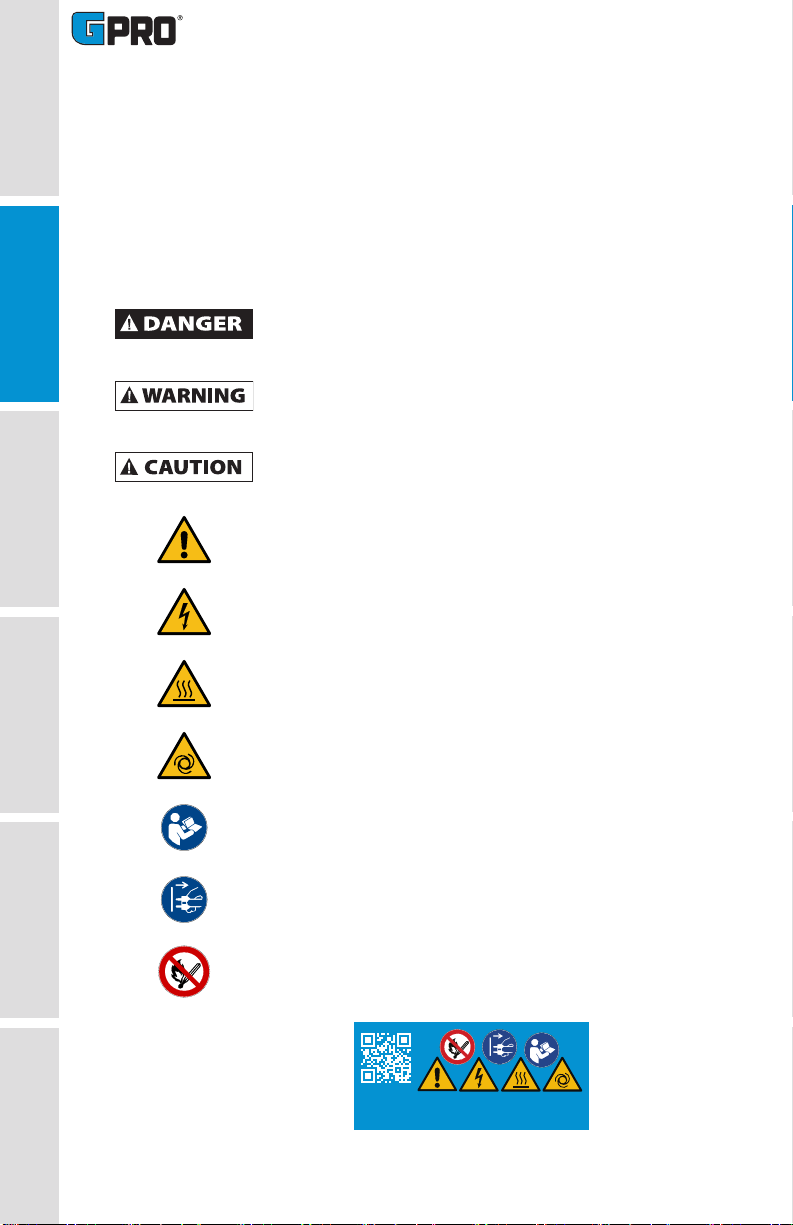
GENERAL SAFETY INSTRUCTIONS (CONTINUED)
SAFETY WARNINGS
To prevent physical injury or property damage, observe
precautions against fire or explosion when dispensing fuel. Do
not operate the system in the presence of any source of ignition
including running or hot engines, lighted tobacco products, gas
or electric heaters, or any type of electronic device. A spark can
ignite fuel vapors.
Observe precautions against electrical shock when operating
the system. Serious or fatal shock can result from operating
electrical equipment in damp or wet locations.
Observe precautions against electrical shock when servicing
the pump. Always disconnect power before repairing or
servicing. Never apply electrical power to the system when any
of the cover plates are removed.
To ensure safe operation, all fuel transfer systems must be
properly grounded. Proper grounding means a continuous
metal-to-metal contact from one component to the next,
including tank, tank mount, pump, meter, filter, hose and nozzle.
Care should be taken to ensure proper grounding during initial
installation and after any service or repair procedures. For your
safety, please take a moment to review the warnings below.
Inspect external pump wiring regularly to make sure it is
correctly attached to the battery. To avoid electrical shock, use
extra care when connecting the pump to power.
Avoid prolonged skin contact with petroleum fuels. Use
protective goggles, gloves and aprons in case of splashing or
spills. Change saturated clothing and wash skin promptly with
soap and water.
All wetted connections should be sealed with appropriate
sealant, thread tape, O-rings, and securely fastened. Leaking
fuel may cause the potential for fire and explosion.
PUMP MODELS THAT MAY BE USED IN AVIATION REFUELING
(PO/PX MODELS) ARE NOT SUPPLIED WITH APPROPRIATE HOSE, NOZZLE,
AND SUCTION PIPE. THESE ITEMS MUST MEET NFPA 407 GUIDELINES.
For ground-based refueling only. Do not use in or on
the aircraft. For use with aviation gasoline (AVGAS
100LL) and kerosene grade (Jet A). User should consult
NFPA 407 Standard for Aircraft Fuel Servicing for safety
requirements during ground fuel servicing of aircraft using
liquid petroleum fuels. This product has no actual or implied
compliance with this standard.
This pump is provided with an internal auxiliary temperature-
limiting device which automatically shuts off the motor before
overheating. The pump will turn back on automatically after
cooling if the switch is not in the off position. Turn the switch
OFF and wait 30 minutes to resume normal operation.
If using solvent to clean pump components or tank, observe the
solvent manufacturer’s recommendations for safe
use and disposal.