6
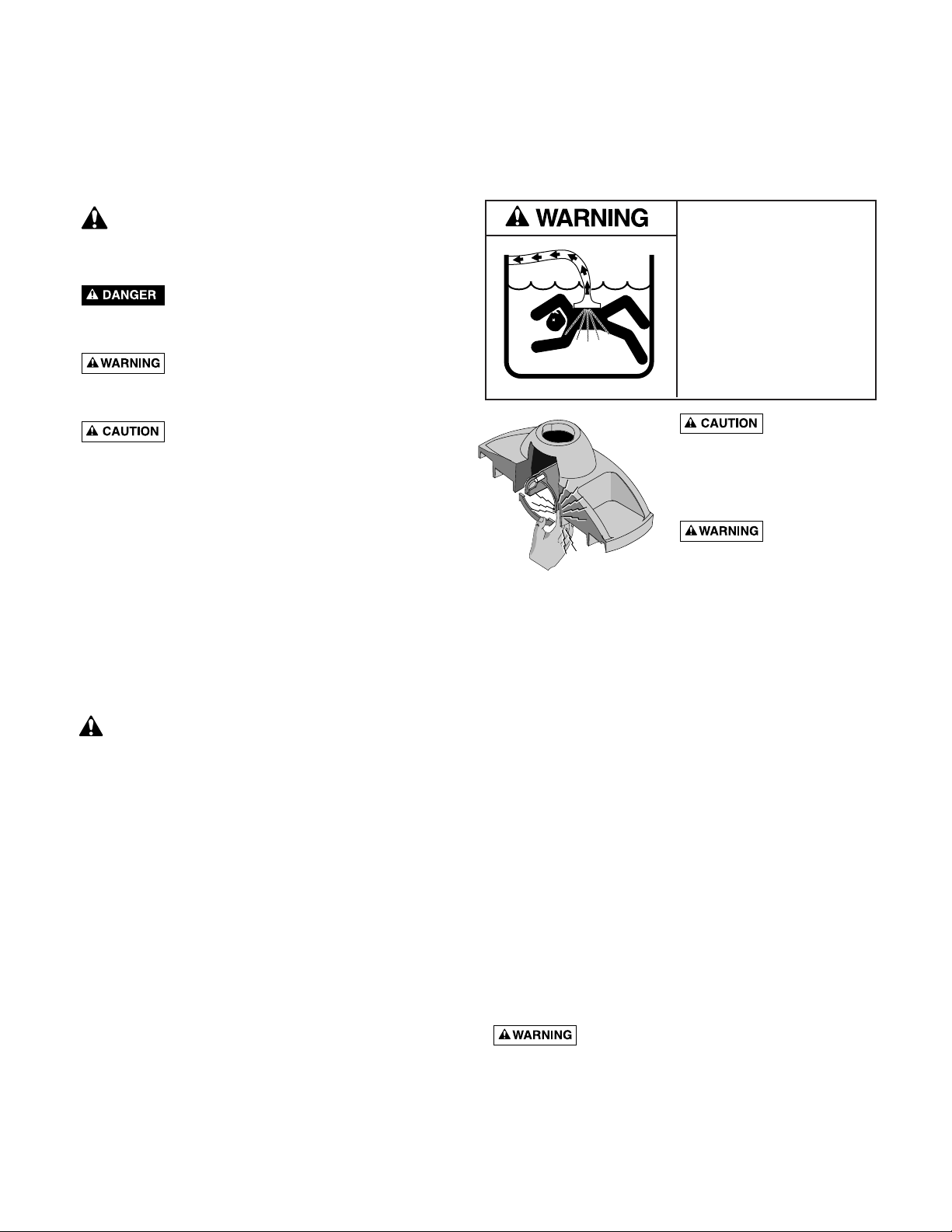
Pool pump suction is hazardous and
can cause entrapment with severe personal injury or
drowning. Use vacuum regulator (see instructions below)
in pool cleaner system at all times.
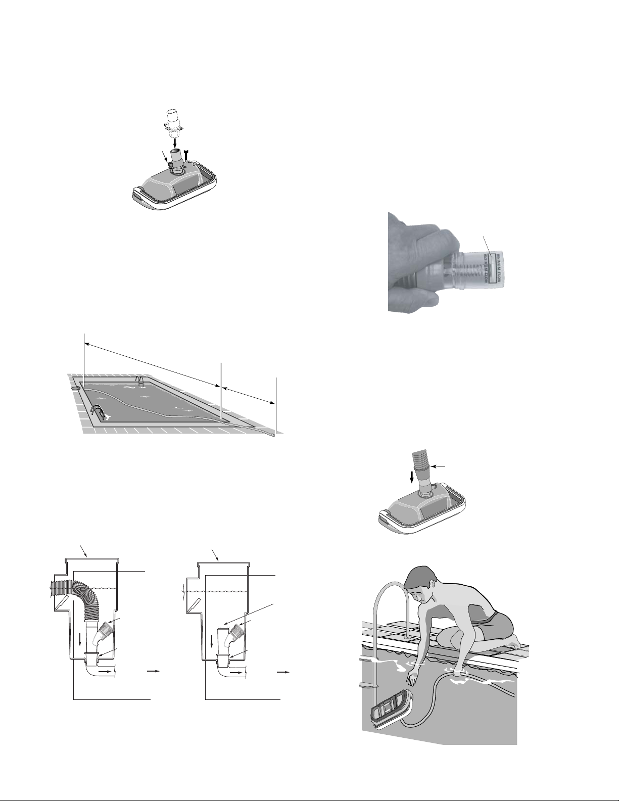
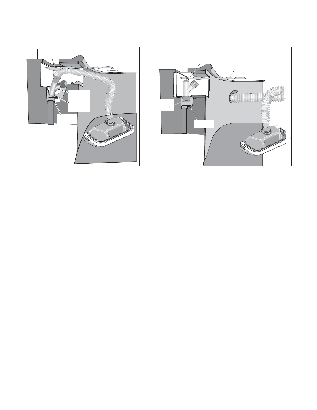
Note: Each pool’s hydraulic system and vacuum connec-
tions are different. Be sure you have installed the white
plastic vacuum regulator before you “fine-tune” the sys-
tem. This not only regulates vacuum, but also acts as a
safety device.
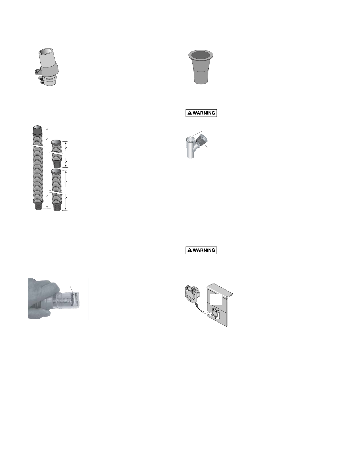
Suction entrapment, injury, and drown-
ing hazard. If your pool has a dedicated suction port
(“vac port”) for vacuuming or for an automatic pool
cleaner, it must be covered when not in use. A spring
loaded safety cover (the “Vac Port Fitting”) is included
with this pool cleaner. Install it on the suction port to pre-
vent entrapment and injury. For details please refer to the
Vac Port instruction sheet included with your Vac Port.
For the
“NOVICE POOL OWNER”
where vacuuming is a
new experience, please read all of the following points,
installation instructions, and trouble shooting guide carefully.
Please note the following:
• “
Vacuum
” and “
suction
” are two words meaning the same
thing.
• “
Dedicated suction line
”, “
vac port
”, and “
vac fitting
” are
different terms for a hole in the side wall of pool; this hole
is connected to the pump suction and is dedicated to
vacuuming.
• Some pools do not have a vac port. If your pool does have
one, please read the “Suction Entrapment” warning above.
For the
“SEASONED POOL OWNER”
: The automatic pool
cleaner connection and vacuum adjustments can be similar
to using your manual pool vacuum. Please read on.
Valves (pump, skimmer, and main drain)
and vacuum adjustments
You may need to spend some time adjusting the skimmer
and main drain valves in order to obtain the best vacuum
setting for good cleaner operation. Once you have found
the correct valve settings for best operation, we suggest you
mark the valves to ensure repeated success.
At first, set valves to give maximum vacuum to the skim-
mer or vac fitting you have elected to use.
Too much vacuum?
You have too much vacuum if the cleaner climbs up the pool
wall past the water line to the point that the cleaner sucks air
and the pump loses prime. Frequent loss of prime will dam-
age the pump. To correct this, adjust the regulator by turning
the adjustment know counter-clockwise. This will decrease
the suction. If the cleaner still climbs out and sucks air, open
the main drain valve slightly.
Not enough vacuum ?
You don’t have enough vacuum if the cleaner moves slug-
gishly or not at all. Be sure the filter system is clean and the
regulator and all valves are adjusted to give you maximum
vacuum. If the cleaner is still not moving, your pump may
not be strong enough to operate the cleaner. Also, please
refer to the Troubleshooting guide on Page 8.
In-Line leaf canisters
If your pool is exposed to large quantities of leaves, we sug-
gest purchasing and installing an in-line leaf canister. A leaf
canister will provide more debris-loading capacity and also
provides a water by-pass when the canister is full. It is very
important that the pump not starve for water!
Dedicated suction line/vac port/vac fitting
Some pools have a dedicated wall fitting just for vacuum-
ing. If the wall fitting connection is used, you may notice
that the clear pump lid shows signs of bubbles or what
appears to be the presence of air. To eliminate this, slightly
open the main drain valve to supplement the water intake.
The cleaner may slow down a bit when you change the
suction.
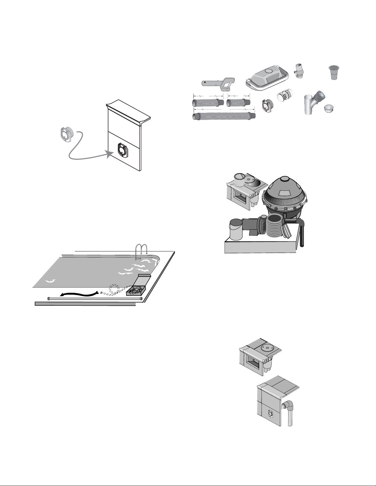
Skimmer connection
Some pool owners remove the skimmer basket and con-
nect the hose directly into the bottom of the skimmer. This
method is OK for pools with minimal debris
and also for screened in pools.
For pools that have large quantities of “big stuff” to pick up,
we suggest using the bottom of the skimmer connection in
conjunction with an in-line leaf canister (purchase the can-
nister locally). A leaf canister will provide more debris-
loading capacity and also provides a water by-pass when
the canister is full.
It is very important that the pump not
starve for water!
Skimmer vac plates
Some pool owners connect the hose to a skimmer vac
plate, which allows the skimmer basket to remain in the
skimmer. If this method is used, empty the basket frequent-
ly. Also make sure that the vacuum regulator provided is
completely submerged so that it will not suck air and dam-
age the pump.
Skimmer vac plate vacuum
control adjusters
Some pool owners use one of a variety of manufacturer’s
skimmer vac plates. Some have a vacuum control adjuster,
and some do not. The adjuster could be a screw-type, a
spring loaded apparatus, or a dial design. For those vac
plates with adjusters, it is important to adjust them when
fine tuning the vacuum for the cleaner.
ABOUT “FINE-TUNING” VACUUM ADJUSTMENTS AND CONNECTIONS:
If you have any questions, please call 1-800-752-0183