manuals.online logo
Brands
  1. Home
  2. •
  3. Brands
  4. •
  5. Green Creative
  6. •
  7. Light Fixture
  8. •
  9. Green Creative 16T8/4F/BYP Series User manual

Green Creative 16T8/4F/BYP Series User manual

Ref.#: INS061-T8-BYP-070317
WARNING - Risk of fire or electric shock. LED Retrofit Kit installation requires knowledge of luminaire electrical systems. Installation should be performed only by a qualified
electrician in accordance with the National Electrical Code and relevant local code.
WARNING - Risk of fire or electric shock. Install this kit only in the luminaires that have the construction features and dimensions shown in the photographs and/or drawings.
WARNING - To prevent wiring damage or abrasion, do not expose wiring to edges of sheet metal or other sharp objects.
WARNING -Risk of fire or electric shock. Luminaire wiring and electrical parts may be damaged when drilling for installation of LED retrofit kit. Check for enclosed wiring and
components.
• Disconnect power at the source before installation, inspection or removal. Do not simply switch off fixture.
• This item is rated at 120-277V. Installer must determine whether line voltage 120-277V is available at the luminaire before installation.
• Not intended for use with emergency exit fixtures or emergency exit lights.
• Not for use with luminaire ballast.
• Do not use if product is damaged.
• This lamp is non-dimmable. Not for use with dimmers.
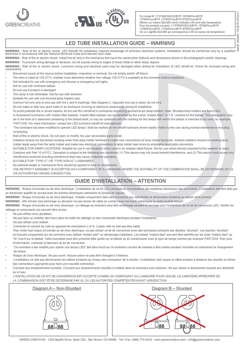
• Suitable for use with non-shunted lamp holders only.
• Connect hot wire only to end cap with the L and N markings. See Diagram 2. Opposite end cap is dead, do not wire.
• Do not make or alter any open holes in an enclosure of wiring or electrical components during kit installation.
• To avoid potential fire or shock hazard, do not use this retrofit kit in luminaires employing shunted bi-pin lamp holders. Note: Shunted lamp holders are found only
in fluorescent luminaires with Instant-Start ballasts. Instant-Start ballasts can be identified by the words “Instant Start” or “I.S.” marked on the ballast. This designation may
be in the form of a statement pertaining to the ballast itself, or may be combined with the marking for the lamps with which the ballast is intended to be used, for example,
F40T12/IS. For more information, contact the LED luminaire retrofit kit manufacturer.
• “This luminaire has been modified to operate LED lamps” shall be marked on the retrofit luminaire where readily visible by the user during normal maintenance including
re-lamping.
• Risk of fire or electric shock. Do not open or modify. No user serviceable parts inside.
• Installers should not disconnect existing wires from lamp holder terminals to make new connections at lamp holder terminals. Instead installers should cut existing lamp
holder leads away from the lamp holder and make new electrical connections to lamp holder lead wires by employing applicable connectors.
• SUITABLE FOR DAMP LOCATIONS. Suitable for use in wet locations when used in an outdoor-rated fixture. Not for use where directly exposed to the weather or water.
• Complies with Part 15 of FCC. Operation is subject to the following two conditions: (1) This device may not cause harmful interference, and (2) This device must accept any
interference received including interference that may cause undesired operation.
• SUITABLE FOR “TYPE IC” OR “TYPE NON-IC” LUMINAIRES.
• No external weight or mechanical force should be applied to tube or components.
• THE RETROFIT ASSEMBLY IS ACCEPTED AS A COMPONENT OF A LUMINAIRE WHERE THE SUITABILITY OF THE COMBINATION SHALL BE DETERMINED BY UL
OR AUTHORITIES HAVING JURISDICTION.
LED TUBE INSTALLATION GUIDE – WARNING
GUIDE D'INSTALLATION – ATTENTION
WARNING - Risque d’incendie ou de choc électrique. L’installation de ce kit LED nécéssite la connaissance des systèmes électriques des luminaires. L’installation doit être faite par
un électricien qualifié en accord avec les normes électriques nationales et locales en vigueur.
WARNING - Risque d’incendie ou de choc électrique. Installer uniquement dans des luminaires aux spécificités et dimensions similaires au dessin et/ou photos.
WARNING - Afin d’éviter tout dommage ou abrasion ne pas laisser de câble en contact avec les bords métaliques ou autre endroit abrasif.
WARNING - Risque d’incendie ou de choc électrique. Le câblage du luminaire peut être endomagé pendant le perçage pour l’installation de ce kit de conversion LED. Vérifier les
câblage et composants qui peuvent être enclos.
• Ne pas utiliser avec gradateur.
• Ne pas faire ou modifier des trous dans les boîte de câblage ou tout composant électrique pendant l’installation.
• Ne pas utiliser avec ballast.
• Connecter le courant du coté ou apparait les inscriptions L et N. L’autre coté ne doit pas être cablé.
• Pour éviter tout risque d’incendie ou de choc électrique, ne pas utiliser ce kit de conversion avec des luminaires utilisants des douilles “shunted”. Les douilles “shunted”
se trouvent uniquement sur les luminaire avec ballast “instant start” ou démarrage instantané. Les ballast “instant start” peuvent être identifié par les mots “instant start” ou
“IS” inscrit sur le ballast. Cette inscription peut être présente telle quelle sur le ballast ou en combinaison avec le type de lampe comme par example F40T12/IS. Pour plus
d’information, contacter le fabricant du kit de conversion.
• “Ce luminaire a été modifié pour opérer une lampe LED” doit être inscrit sur le luminaire converti de manière à être visible pendant l’entretien et notamment le changement
de lampe.
• Risque de choc électrique. Ne pas ouvrir. Aucune pièce ne peut être changée à l’intérieur.
• L’installateur ne doit pas déconnecter les câbles existants au niveau des connecteur de la douille. L’installateur doit couper le câble existant à distance des douilles et utiliser
des connecteurs appropriés pour faire une nouvelle connection.
• Convient aux emplacements humides. Convient aux emplacements mouillés si installé dans un luminaire pour extérieur. Ne pas utiliser si directement exposé aux éléments
ou à l’eau.
• L’INSTALLATION DE CE KIT DE CONVERSION EST ACCEPTÉ COMME UN COMPOSANT DU LUMINAIRE POUR LEQUEL LE CARATÈRE APPROPRIÉ DE
LA COMBINAISON DOIT ÊTRE DETERMINÉ PAR UL OU LES AUTORITÉS COMPÉTENTES AYANT JURISDICTION.
Diagram A – Non-Shunted Diagram B – Shunted
For model #: 17.5T8/4F/GOLD/BYP, 16T8/4F/xxx/BYP,
13T8/4F/xxx/BYP, 12T8/3F/xxx/BYP, 8T8/2F/xxx/BYP
Where xxx means 824-965 which indicates CRI and color temperature
Pour les produits suivants: 17.5T8/4F/GOLD/BYP, 16T8/4F/xxx/BYP,
13T8/4F/xxx/BYP, 12T8/3F/xxx/BYP, 8T8/2F/xxx/BYP
Où xxx signifie 824-965 qui correspond au CRI et couleur de température
LED TUBE INSTALLATION GUIDE – INSTALLATION STEPS / GUIDE D’INSTALLATION – ETAPES D’INSTALLATION
1) Read all WARNINGS before continuing this section.
2) Ensure fixture is 120-277V.
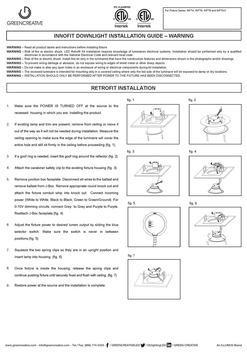
3) Make sure POWER IS TURNED OFF AT THE SOURCE.
4) Remove lens if applicable, remove cover and fluorescent
tubes.
5) Cut all wires that connect ballast (Cf. Diagram 1).
Properly discard ballast or cap off wires. Cut wire away from
lamp holders.
6) If applicable, replace lamp holders at power end with
non-shunted lamp holders.
7) Connect Live (L) from power source into non-Shunted
lamp holder “L In”.
8) Connect neutral (N) wire from power source into
non-Shunted lamp holder “N In”.
9) If installing a single tube refer to Diagram 3 and go to
section 13. If connecting multiple lamps, continue reading.
10) Connect separate hot wire into “Hot Out” from primary
source lamp holder and connect that wire into “Hot In” on the
adjacent tube.
11) Connect separate neutral wire into “Neutral Out” from
primary source lamp holder and connect that wire into
“Neutral In” on the adjacent tube. See Diagram 4 below.
12) Continue this process for additional lamps.
13) This device is powered on one end only; the end with L
and N markings (Cf. Diagram 2). Do not wire opposite end of
lamp holder.
14) Install lamp with the L and N markings into the wired
lamp holder end.
15) Visibly affix “Modification Sticker” and reinstall housing
cover and lens if applicable.
16) Return power back to source and installation is now
completed.
1) Lire tous les points d’ATTENTION.
2) Verifier que le luminaire soit bien en 120-277V.
3) Assurez-vous que le courant soit coupé à la source.
4) Retirez l’optique et capot du luminaire (si nécéssaire) et
retirez les tubes fluorescents.
5) Coupez tous les câbles de connection du ballast (Cf.
Diagram 1). Couper les câble à distance des douilles.
6) Remplacer les douilles “shunted” pas des douilles
“non-shunted” si nécéssaire.
7) Connecter la partie “Live” (L) de la source de courant
dans la douille “non-shunted” “L IN”.
8) Connecter la partie “Neutral” (N) de la source de courant
dans la douille “non-shunted” “N IN”.
9) Si l’installation se compose d’un seul tube, se référrer au
Diagram 3 et passer directement à l’étape 13. Si l’installation
est composée de plusieurs tubes, continuez à lire.
10) Connecter le câble supplementaire “Live” (L) ou “HOT”
dans le connecteur “Hot Out” de la premiere douille et
connecter l’autre extremite dans le connecteur “Hot In” du
tube suivant.
11) Connecter le câble “supplémentaire “Neutral” (N) dans le
connecteur “Neutral Out” de la premiere douille et connecter
l’autre extremité dans le connecteur “Neutral In” du tube
suivant. Voir Diagram 4.
12) Répéter l’opération pour les tubes suivants.
13) Ce tube est alimenté par un seul coté, il s’agit du coté ou
les inscriptions L et N sont visibles (voir Diagram 2).
14) Installer l’extrémité du tube avec les inscriptions L et N
dans la douille qui a été cablée.
15) Coller l’autcollant de modification de manière visible sur
le luminaire.
16) Refermer le luminaire et remetter le courant, l’installation
est terminèe.
Diagram 2 – Connecting end
Power
Source
3 Lamp
Configuration
Diagram 1 – Cut all ballast wires
Cut all wires connecting ballast.
Connect power to end with L and N markings.
Only wire to one end, the end with L and N markings.
Wiring should be made using non shunted lamp holder.
Diagram 3 – Single tube wiring
Only wire to one end, the end with L and N markings.
Wiring should be made using non shunted lamp holder.
Maximum 4 tubes should be interconnected.
Diagram 4 – Multiple tube wiring
L N
Ballast
L N L N L NL N
L
N
Ballast
Ballast
L N
L
N
In
Out In
Out
Hot Neutral
For model #: 17.5T8/4F/GOLD/BYP, 16T8/4F/xxx/BYP,
13T8/4F/xxx/BYP, 12T8/3F/xxx/BYP, 8T8/2F/xxx/BYP
Where xxx means 824-965 which indicates CRI and color temperature
Pour les produits suivants: 17.5T8/4F/GOLD/BYP, 16T8/4F/xxx/BYP,
13T8/4F/xxx/BYP, 12T8/3F/xxx/BYP, 8T8/2F/xxx/BYP
Où xxx signifie 824-965 qui correspond au CRI et couleur de température

This manual suits for next models

4

Other Green Creative Light Fixture manuals

Green Creative 17.5T8/4F/GOLD/BYP User manual

Green Creative

Green Creative 17.5T8/4F/GOLD/BYP User manual

Green Creative INNOFIT INFT4 User manual

Green Creative

Green Creative INNOFIT INFT4 User manual

Green Creative 17T8U6 Series User manual

Green Creative

Green Creative 17T8U6 Series User manual

Popular Light Fixture manuals by other brands

Square Perfect 2815 SP1 Assembly and user's manual

Square Perfect

Square Perfect 2815 SP1 Assembly and user's manual

Cooper Lighting METALUX RWW Series Specifications

Cooper Lighting

Cooper Lighting METALUX RWW Series Specifications

Malmbergs MD-29 instruction manual

Malmbergs

Malmbergs MD-29 instruction manual

Chauvet PK PAR64C user manual

Chauvet

Chauvet PK PAR64C user manual

Hayward ColorLogic® 4.0 owner's guide

Hayward

Hayward ColorLogic® 4.0 owner's guide

Home Decorators Collection 29800 Use and care guide

Home Decorators Collection

Home Decorators Collection 29800 Use and care guide

Edwards Signaling AdaptaBeacon  94DV2-N5 Series installation instructions

Edwards Signaling

Edwards Signaling AdaptaBeacon 94DV2-N5 Series installation instructions

ETI EM-EX-R Use and care guide

ETI

ETI EM-EX-R Use and care guide

Larson Electronics ATEX-EPL-TL-3X10W-C instruction manual

Larson Electronics

Larson Electronics ATEX-EPL-TL-3X10W-C instruction manual

Rebel Light URZ3331 owner's manual

Rebel Light

Rebel Light URZ3331 owner's manual

CREE LIGHTING Cadiant Experience Dynamic Skylight installation instructions

CREE LIGHTING

CREE LIGHTING Cadiant Experience Dynamic Skylight installation instructions

Philips Calculite C4T4GA-MHT4RF specification

Philips

Philips Calculite C4T4GA-MHT4RF specification

bocci 44.3 Products Installation Instructions

bocci

bocci 44.3 Products Installation Instructions

Exido Daylight Lamp 237-004 Specifications

Exido

Exido Daylight Lamp 237-004 Specifications

Axis SLIM SurroundLite installation instructions

Axis

Axis SLIM SurroundLite installation instructions

Lightolier RADIANCE PENDANT FIXTURES Instructions for installation

Lightolier

Lightolier RADIANCE PENDANT FIXTURES Instructions for installation

Cooper Lighting PM135cb Specification sheet

Cooper Lighting

Cooper Lighting PM135cb Specification sheet

Sagitter SG HALFPAR6 user manual

Sagitter

Sagitter SG HALFPAR6 user manual

manuals.online logo
manuals.online logoBrands
  • About & Mission
  • Contact us
  • Privacy Policy
  • Terms and Conditions

Copyright 2025 Manuals.Online. All Rights Reserved.