Schrack Technik KIZ User manual

CONNECTING COMPETENCE.
ENERGY INDUSTRY BUILDINGS SAFETY DATA CABLE LIGHT
PRODUCT MANUAL FOR THE
COMPACT INDUSTRY METER KIZ
WINSTALLATION
WDEVICE DESCRIPTION
WOPERATION

Page
2
3
Tabl e of conten ts
1
Prologue
...........................................................................
.
1.1 Saftey tips .................................................................................
.
1.2 Maintenance and guarantee tips.................................................
.
2
Mo un tin g a nd i ns ta lla tio n
................................................
.
2.1 Mounting the meter ....................................................................
.
2.2 Installation .................................................................................
.
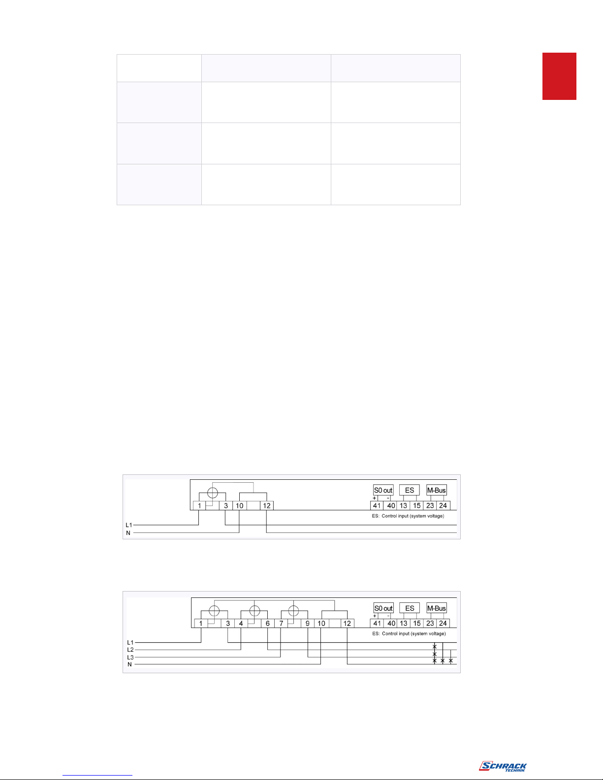
2.2.1 Connection examples.................................................................
.
3
General descript ion
.........................................................
.
4
St an da rds a nd re gu la tio ns
..............................................
.
5
Ho us in g- , o pe ra ti on an d d isp l ay el e me nts
.....................
.
5.1 Overview ...................................................................................
.
5.2 LC-Display.................................................................................
.
5.3 Display elements .......................................................................
.
6
T ec hn ic al de sc r ip ti on
......................................................
.
6.1 Technical data ...........................................................................
.
6.2 Function circuit diagrams ...........................................................
.
6.3 Inputs ........................................................................................
.
6.4 Outputs .....................................................................................
.
6.4.1 Test-LED ...................................................................................
.
6.5 Interfaces ..................................................................................
.
6.5.1 M-Bus-interface .........................................................................
.
7 Articles ..............................................................................
Figu re inde x
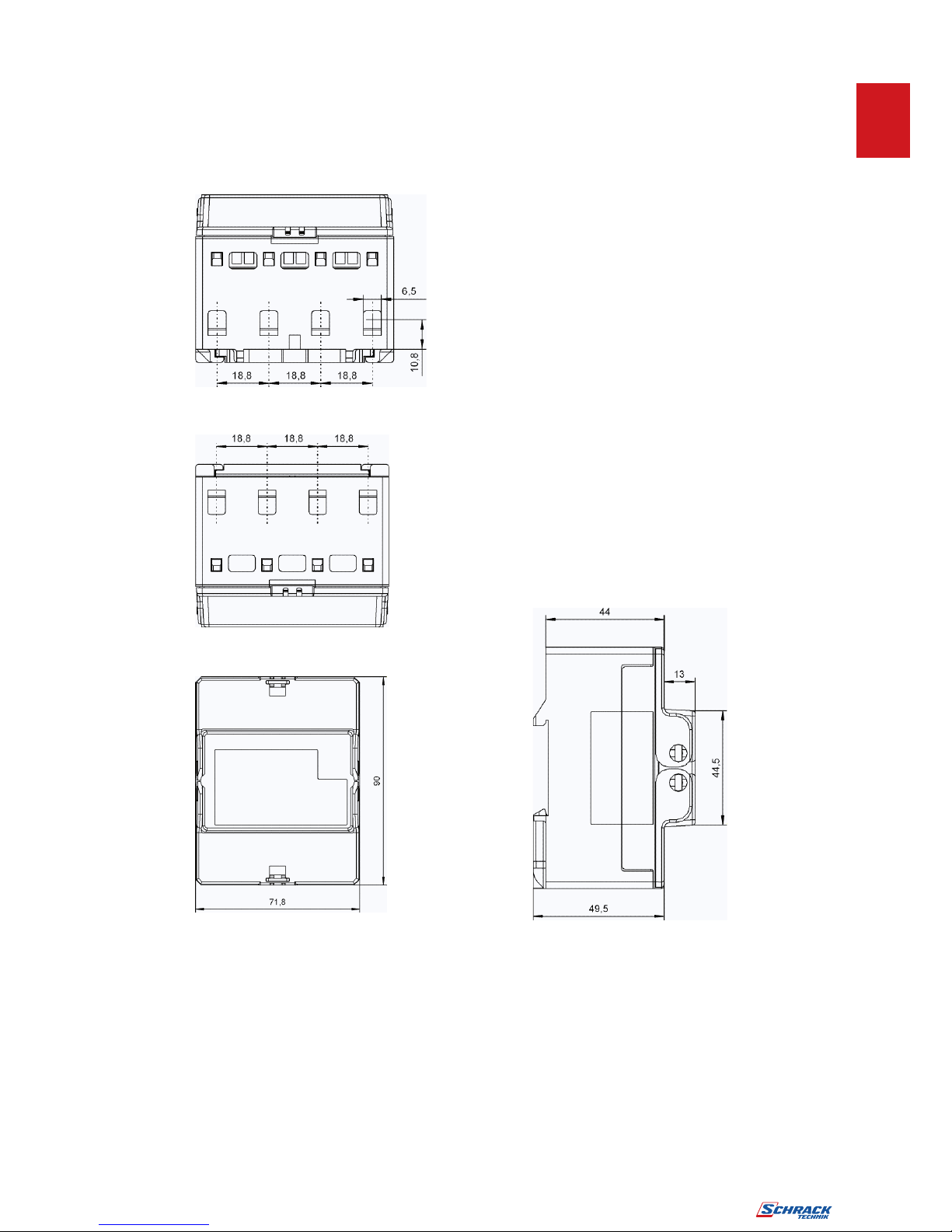
Figure 1: Dimensions................................................................................
.
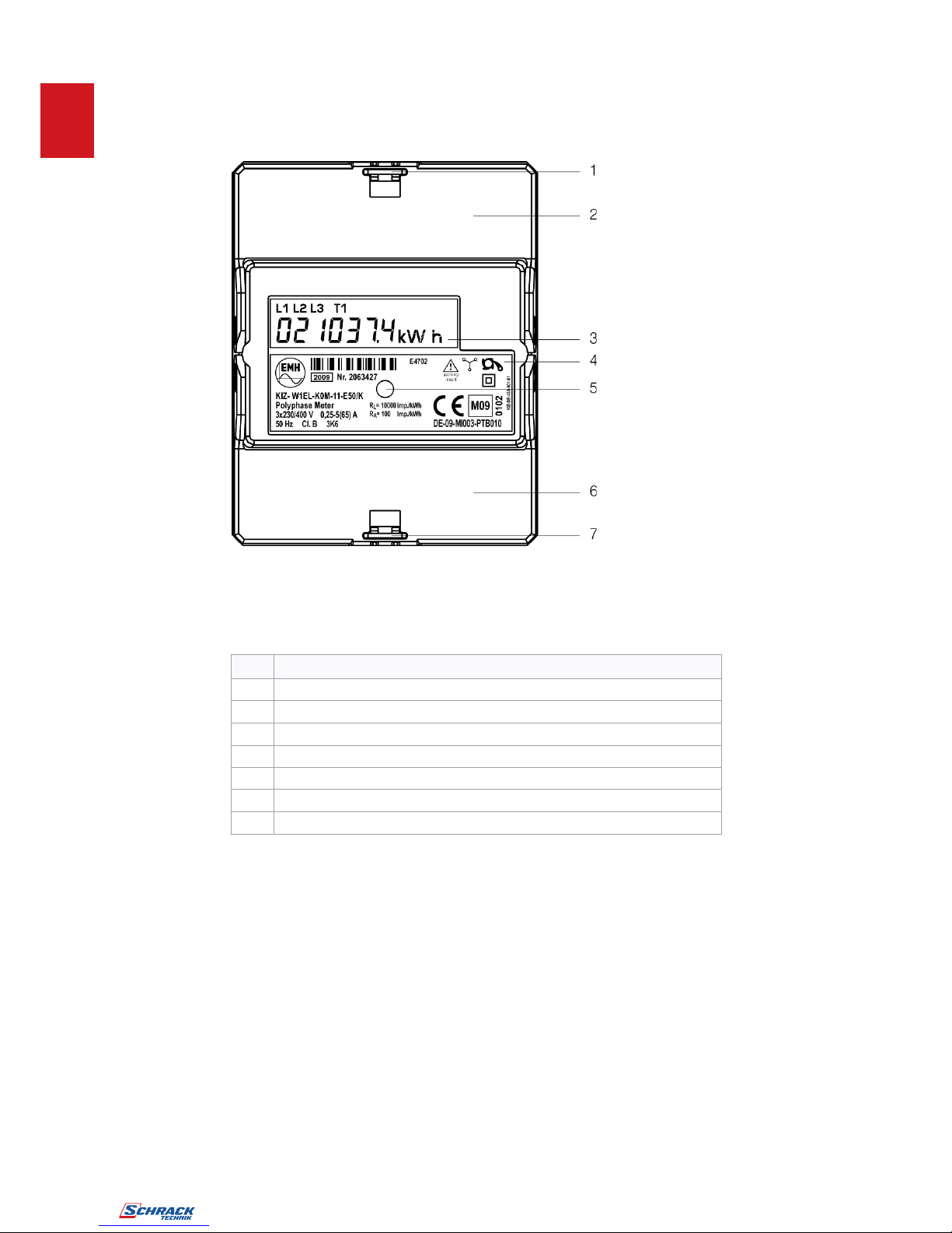
Figure 2: Housing-, operation and display elements...................................
.
Figure 3: Layout of the display ..................................................................
.
Figure 4: Function circuit diagram .............................................................
.
Tabl e index
Table 1: Terminal dimensions, connection-cross sections, torques............
.
Table 2: Housing- and display elements...................................................
.
Table 3: Description of the display elements.............................................
.
Table 4: Display elements .......................................................................
.
Table 5: Technical data ...........................................................................
.
Table 6: Specification of the input ............................................................
.
Table 7: Specification of the output ..........................................................
.
4
4
4
5
5
6
7
8
9
10
10
11
12
13
13
14
15
15
15
15
15
16
5
10
11
14
7
10
11
12
13
15
15

Page
3
4
Abbre viatio n
s
s
A Active energy
+A Positive active energy (customer imports from utility)
-A Negative active energy (customer exports to utility)
Cl. Accuracy class
DIN Deutsches Institut für Normung e.V.
(German Institute for standards)
EN European standards
EVU Utility
IEC International Electromechanical Commission
Imp. Impulse
Imp./kWh Impulse per kWh
L1, L2, L3 External conductor
LED Light Emitting Diode
N Neutral conductor
P Active power
PTB PTB (German certified body)
S0 Interface accord. to DIN 43 864

5
1
Prologue
This manual describes all designs of the meter. Please note that the meters can be
designed differently regarding, for example, configuration, interfaces in-/outputs etc. It is
therefore possible that meter features are described here which do not apply to the
meter(s) used by you.
1.1
Saf ety tips
The meters are to be used exclusively for measuring electrical energy and must only be
operated within the specified technical data (see also nameplate).
When installing or changing the meter, the conductor to which the meter is connected
must be de-energised. Only the intended screw terminals may be used for this. Contact
to parts under voltage is e
ex tre me ly d an ge ro us .
Therefore the relevant back-up fuse is
to be removed and stored so that other people cannot insert this unnoticed.
With incorrect meter installation the S0-inputs can lead to line voltage.
At te n tio n : Da ng e r !
The local standards, guidelines, regulations and instructions are to be obeyed.
Only authorized personnel are permitted to install the electricity meters.
1.2
M ai n te n an ce a nd gua ra nt ee t i ps
The meter is maintenance-free. With damages (e.g. due to transportation, storing) no
repairs may be carried out independently.
As soon as the meter is opened, the guarantee claims cease. The same applies in case
the defect can be traced back to external influences (e.g. lightning, water, fire, extreme
temperatures and weather conditions, improper or negligent use or treatment).
Page
4

Page
5
6
2
Moun ting a nd in st allation
2.1
Mou ntin g the m et er
The meter is designed for mounting on DIN-rails TH 35-7.5 accord. to DIN 60715.
Figure 1: Dimensions

7
2.2
Ins t al lati on
When installing the meter, please pay careful attention to the connection diagram which
can be found on the inside of the terminal cover. On page 8 you can find examples of
connection diagrams.
The meter must be secured with an overcurrent protection device of 63 A.
.
The control
input is to be protected with a back-up fuse of 0,5 A.
In order to protect the meter from unauthorized access, the meter can be equipped with
a seal at the sealing eye (see page 11).
The current and voltage supply inputs can be found on the top of the meter.
The current outputs, the optional electrical interface, the control input and the impulse
output can be found on the bottom of the meter.
Page
6

Page
7
8
Curren
t
t te rm in a l
s
s
/
/
N
-
- te rm in a ls
Voltag
e
e
/
/ Au x ili a r
y
y
terminals
Terminal
dimensions
W x H (d) mm
6,4 x 6,5 d= 2,5
Maximum
connection-cross
section (mm2)
16 2,5
Maximum
torques for
terminals (Nm)
3,0 0,8
Table 1: Terminal dimensions, connection-cross sections, torques
Note
:
:
Please ensure when installing the meter that, after threading the connecting leads,
the screws are tightened to the correct torque according to EN 60999 in order to
guarantee a safe contact. The torque depends on the type of the connecting leads
and the maximum current.
I
n
n o rd e
r
r t
o
o av o i
d
d da mag
e
e t
o
o th
e
e me t e
r
r th
e
e val id
,
, ma x im u
m
m to rq u
e
e fo
r
r th
e
e
termina
l
l c la m p
s
s ma
y
y no
t
t b
e
e ex c e eded
.
.
2.2.
1
1 Co nn ec t io
n
n ex a mple
s
s
In the following you can find examples of some connection diagrams. When connecting a
meter pay attention to the connection diagram which can be found inside the terminal
cover or in the delivery documents.
At te n tio n :
The neutral terminals 10 and 12 are arranged on the left!
2-wire version, direct connection
4-wire version, direct connection

9
3
3 Ge nera
l
l de scriptio
n
n
In the following all design variants of the meter are described.
It is therefore possible that meter features are described which do not apply to the meter
used by you.
The meter is a digital 1- or 2- tariff meter for measuring positive active energy in 2- and
4-wire networks.
Tariff switching takes place via an external control input. The meters are principally used
for energy data registration in the industry and building installation, switching stations
and the field of energy supply. The compact design of this meter allows „space saving“
mounting (only 4 pitch wide).
The meter has a 7-digit LC-display. The energy consumption values are displayed with 6
integer digits and 1 decimal digit.
They can, however, also be given out via a pulse output (max. 27 V DC, 27 mA) and/or
via an electrical interface (M-Bus, according to EN 13757-2, -3). The pulse constant
(100 Imp/kWh) and the pulse length (100 ms) are fixed.
The meter corresponds to the accuracy class B according to EN 50470-1, -3.
Page
8

Page
9
10
4
4 Standard
s
s an
d
d re gula tion s
DIN EN 13757-2, -3 Communication systems for meters and remote reading of
meters
EN 50470-1 Electricity metering equipment (a.c.) - Part 1:
General requirements, tests and test conditions -
Metering equipment (class indexes A, B and C)
EN 50470-3 Electricity metering equipment (a.c.) - Part 3:
Particular requirements - Static meters for active energy
(class indexes A, B and C)
DIN EN 60529 Degrees of protection provided by enclosures (IP code)
DIN EN 60715 Dimensions of low-voltage switchgear and control gear -
standardized mounting on rails for mechanical support of
electrical devices in switchgear and control gear installations
DIN EN 61000-3-2, Electromagnetic compatibility (EMC)
4-2, -4-3, -4-4, -4-5,
-4-6, -4-11, -6-2
IEC 60068-2-30 Environmental testing - Part 2-30: Tests - Test Db:
Damp heat, cyclic (12 h + 12 h cycle)
IEC 62052-11
Electricity metering equipment (AC) - General requirements,
tests and test conditions - Part 11: Metering equipment
IEC 62053-21 Electricity metering equipment (a.c.) - Particular Requirements
- Part 21: Static meters for active energy (classes 1 and 2)
TIA/EIA-485 Electrical characteristics of generators and receivers for
use in balanced digital multipoint systems

11
5 Housi ng- , operatio n and di splay ele m en ts
5.1
Overvi ew
Figure 2: Housing-, operation and display elements
No.
De s crip t io n
1
Sealing eye
2
Terminal cover with connection diagram
3
LC-Display
4
Nameplate
5
Test-LED
6
Terminal cover with description of the auxiliary terminals
7
Sealing eye
Table 2: Housing- and display elements
Page
10

Page
11
12
5.
2
2 L C- Di sp l a
y
y
The meter has a liquid crystal display (LCD) with the following layout.
Figure 3: Layout of the display
No
.
.
Descript io
n
n
1
1
Phas
e
e displa
y
y
L1, L2, L3 are continually lit up: Phase voltages are applied.
L1, L2, L3 flash: Phase sequence of the voltage is wrong
L1, L2, L3 off: Failure of the phase
2
2
Displa
y
y o
f
f ac t iv
e
e ta ri ff
s
s
T1 lights up: Tariff 1 is active, Display tariff register 1
T1 lights up and T2 flashes: Tariff 1 is active, Display tariff register 2
T2 lights up: Tariff 2 is active, Display tariff register 2
T2 lights up and T1 flashes: Tariff 2 is active, Display tariff register 1
3
3
Co mm un ic a tio
n
n symbo
l
l
lights up: When communication with the electrical
interface
4
4
Valu
e
e range
Display the contents of the register
5
5
Unit
s
s
Unit of the displayed value in the
value range
Table 3: Description of the display elements

13
5.3
Di splay ele ments
Not e:
Non-existing functions (e.g. M-Bus) do not appear in the display.
Di sp l ay
De scri pt io n
Du rat i on of
di sp l ay
Display test All display segments
flash after start-up for
approx. 4 s
Firmware- version Appears for 5 s
Check sum Code Appears for 5 s
Error display Appears for 60 s if an
error occurs
Energy value active tariff Appears for 10 s
(in case of error only
4 s)
Energy value inactive tariff Appears for 5 s
Sum of power P
Power P phase 1
Power P phase 2
Power P phase 3
Voltage U phase 1
Voltage U phase 2
Voltage U phase 3
Current I phase 1
Current I phase 2
Current I phase 3
Primary M-Bus-address
Secondary M-Bus-address
MSW (most significant word)
= 4 most significant digits
LSW (least significant word)
= 4 least significant digits
Scrolling list
Display test
Every value appears
for 2 s
Table 4: Display elements
Page
12

Page
13

15
6.2
F un cti on ci rcui t di agr am s
Figure 4: Function circuit diagram
Page
14

Page
15
16
6.3
Inputs
The meter has for the two tariff version a control input (system voltage) for tariff
switching.
Sp ec ifi ca tio ns
System voltage 230 V AC (standard)
Table 6: Specification of the input
6.4
Out put s
The meter has a potential free S0-output (accord. to DIN 43 864).
Sp ec ifi ca tio ns
S0 max. 27 V DC, 27 mA (passive)
Table 7: Specification of the output
The output constant (RA) depends on the version.
6.4.1 T est -LED
The LED constant (RL) depends on the version.
6.5
Int erf ac es
6.5.1
M- Bus - in t er fa ce
The M-Bus interface is designed accord. to DIN EN 13757-2, -3. Via M-Bus the following
parameters can be transmitted:
Manufacturer identification
Medium
Primary- and secondary addresses M-Bus
Energy values
Instantaneous value P (per phase and sum), U and I (per phase)
Error status
This data is emitted as a standard answer and can be displayed by customary tools such
as “Lorus”.
The primary M-Bus-address, the secondary M-Bus-address and the Baud rate can be
changed via the standard M-Bus commands.

17
7 Articles
Digital 4-wire-kWh-meter, type KIZ, direct 65A, 2 tariffs MGKIZ065
Digital 4-wire-kWh-meter, type KIZ, direct 65A, 2 tariffs, with M-Bus MGKIZ365
Digital 2-wire-kWh-meter, type KIZ, direct 65A, 2tariffs MGKIZ165
Digital 2-wire-kWh-meter, type KIZ, direct 65A, 2tariffs, with M-Bus MGKIZ665
All of the contents published in this manual are copyright. Translating, reprinting, duplicating and also saving of this
manual in data processors require the exclusive permission from EMH.
All of the trademarks named in this manual are the property of EMH or the respective title holders.
EMH Elektrizitätszähler GmbH & Co KG is certified accord. to DIN ISO 9001:2000
and continually endeavors to improve their products.
The contents of this manual and the technical specifications can be extended,
altered or removed without prior notice.
The description of the product specifications in this manual does not represent
part of a contract.
© 2009 EMH Elektrizitätszähler GmbH & Co KG. All rights reserved.
If you have any questions or inspirations you can contact us:
SCHRACK Technik GmbH
Seybelgasse 13
AT-1235 Wien
www.schrack.com
Page
16
KIZ-PHB-E-1.30 EDITION: 08.2011
Table of contents
Popular Measuring Instrument manuals by other brands

A&D
A&D Omniace III RA2300A instruction manual

Renishaw
Renishaw RLP40 installation guide

Omega Engineering
Omega Engineering FMA-1600A Series user guide

Hioki
Hioki LR8400-92 instruction manual

Steinberg Systems
Steinberg Systems SBS-SM-130C user manual

Eaton
Eaton Durant Eclipse 5775X-40 Series Installation and operation manual