GreenGLo 180S User manual

USER MANUAL
INSTALLATION INSTRUCTIONS
WARRANTY REGISTER
GREENGLO MAINS PRESSURE INTEGRATED WATER HEATER
SINGLE COIL SERIES & DOUBLE COIL SERIES
GREENGLO SAVER
Customer
Congratu ations for choosing a GreenG o integrated water heater
We recommend you read page 1 to 5 of this manua .
It may save you time and troub e ater.
P ease register the product warranty as per page 20 of this manua
The other pages of the manua are intended for the insta er.
For a further assistance or information contact our service desk
0800 447 336 info@greeng o.co.nz

© GreenGlo Limited Version 05/2010
IMPORTANT INFORMATION
GreenG o are purpose y-bui t heavy duty mains pressure cy inders. Insta ation
of GreenG o cou d be different than other tanks.
GreenG o water heaters must be insta ed by a registered p umber and in
accordance with these insta ation instructions, NZ.3500.4 Nationa p umbing
regu ations; municipa bui ding codes other re evant statutory regu ations.
Observation of these instructions and the associated component instructions is
most important and fai ure to do so cou d void the benefits of warranty.
The information contained in this manua , and a other information or advice
provided by GreenG o Limited in connection with the purchase, insta ation use
and service of GreenG o water heater is given in good faith. GreenG o Limited
wi not be iab e for any person for any inaccuracy or omission in the
information arising through the fau t of GreenG o Limited direct y or indirect y.
A pressure- imiting va ve of 500kPa max rating must be fitted. Fai ure to insta
a pressure imiting va ve where required wi void the warranty.
SAFETY
Sca ding occurs at 50
0
C. This app iance is capab e of providing hot water
above this temperature. A insta ers must advise customers of the potentia
hazard of sca ding in accordance with the re evant Nationa standards
inc uding NZS3500.4.
Young chi dren shou d not p ay with the app iance.
A combination Temperature Pressure Re ief va ve with a maximum rating of
850kPa must be fitted.
Water may drip from the discharge pipe of this va ve.
This pipe must be eft open to the atmosphere.
For more information, p ease refer to the Regu ar Care section on page 5 of
this manua .
A so fitted to the water heater is a specia auto reset thermostat.
These safety devices must not be tempered with or removed from the
app iance under any circumstances.
Use a separate circuit breaker for each of the e ectrica heating e ements
1

© GreenGlo Limited Version 05/2010
ABOUT YOUR WATER HEATER
1. GreenG o & GreenG o Saver is a high techno ogy storage tank, backed up
by new manufacturing methods offering qua ity of goods to consumers.
2. The main goa of producing GreenG o water heaters is heating and storing
potab e hot water in a main pressure storage tank using e ectricity.
GreenG o a so offers optiona heating equipment such as so ar, gas and
wetback. Potab e hot water is stored in the main water storage tank
separate y from the heating f uids in the coi s.
3. The heating f uid, which is heated in the heat source, is circu ated
between the heat source and cy inder’s coi . The warmed f uid takes its
heat from the heat source and transmits to the water heater.
4. GreenG o cy inders inner surface is ename ed. The process used is a
doub e ename ing process that coats the inside surface of the cy inder.
5. GreenG o cy inders are protected by a magnesium anode rod in order to
prevent cathode corrosion. The magnesium anode rod ought to be
checked and rep aced if required, every 36 months by a certified p umber,
and can be done by fo owing this manua page 16.
6. GreenG o exterior surface is covered by 40 kg/m³ and 50 mm
po yurethane insu ation (except 800D and 1000D) in order to diminish the
oss of the heat. The GreenG o 800D and 1000D insu ation is removab e.
This convenience a ows easy de ivery and access through narrow
doorways. Do not remove covers un ess essentia and on y after
receiving specific instructions from GreenG o service desk
7. GreenG o is an indoor tank and sha be insta in a we vented space to
prevent condensation
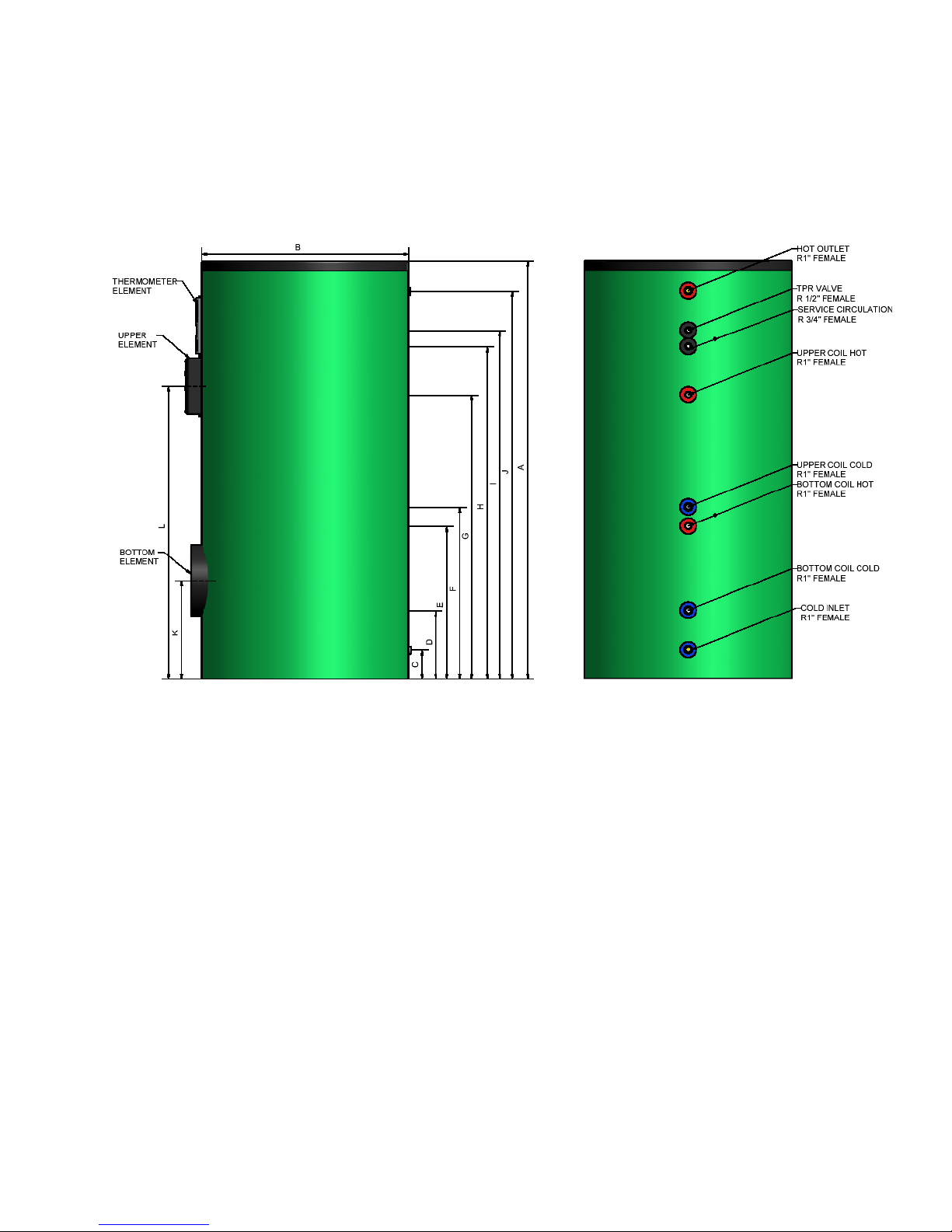
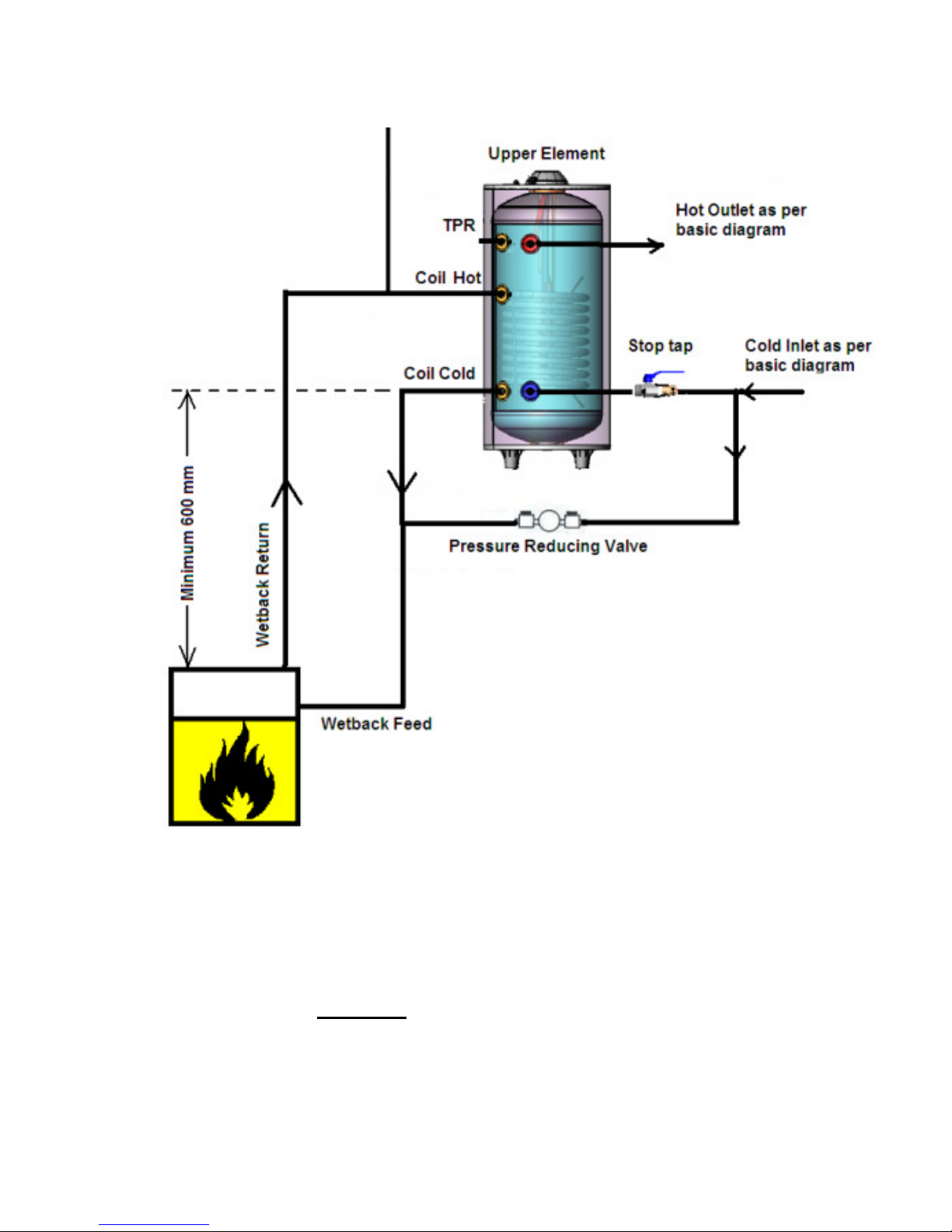
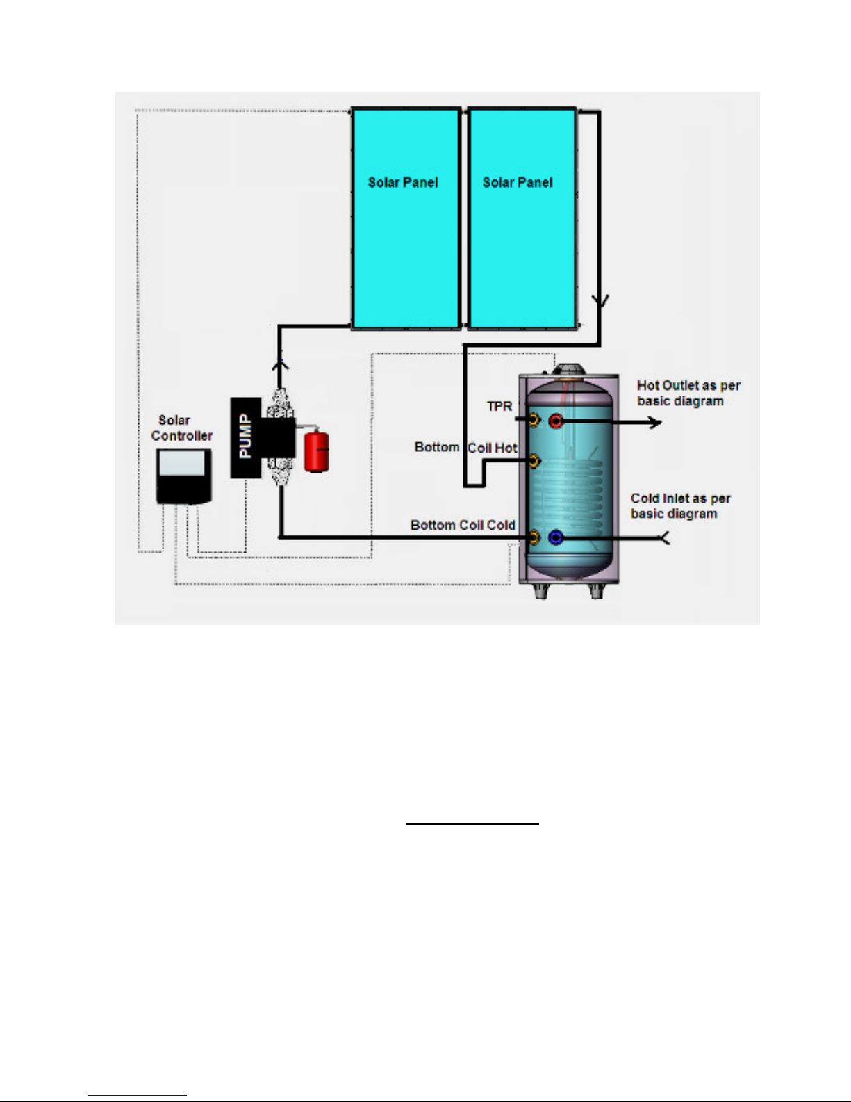
8. There is a choice of doub e or sing e or doub e coi GreenG o depending on
the app ication needed. I.E. if the cy inder wi be heated with a wetback
or a so ar system, GreenG o sing e coi water heater wou d be appropriate.
On the other hand, if the cy inder wi be heated with both wetback and a
so ar system, GreenG o doub e coi wou d be appropriate.
9. GreenG o water heaters have been produced to suit a wide range of
app ications and insta ations and are comp ying with NZS4606
In this manua we present the most common app ications, however if you
require advice on any other app ication, p ease contact our service desk on
0800 447 336 or info@greeng o.co.nz
2

© GreenGlo Limited Version 05/2010
PRODUCT INFORMATION
Note: 800D & 1000D foam insu ation is removab e
Do not remove cover un ess essentia
Contact GreenG o service desk before remova of cover
A GreenG o mode s have a soft b anket cover for extra insu ation
GreenGlo S ver
Setup and usage instructions of the GreenG o Saver contro er are avai ab e with the
contro er instructions book provided with the product.
The contro er is pre-wired and therefore no specia insta ation instructions are
necessary.
3

© GreenGlo Limited Version 05/2010
PRODUCT INFORMATION
Gener l product inform tion
Maximum working pressure 800kPa
Maximum water temperature 90°C
Maximum coi s working pressure 800kPa
Maximum heat exchange temperature 95°C
Ename ed stee automatica y we ded
50 mm po yurethane in accordance to NZS4692.1 and NZS4692.2
Indoor use on y
Note : The product must not be exposed direct sun ight, rain, etc. Uninsu ated pipework
exposed to outdoor decrease heater performance & may increased energy consumption.
Specific product inform tion
180S 300S
180D
300D 300DS
400D 500D 800D 1000D
Dimensions may
change without notice
Sing e Coi
S Series
Doub e Coi
D Series
Vo ume
( itres)
180 300 180 300 300 400 500 800 1,000
A – Height
(mm)
1650
1780
1650 1780 1240
1580 1860 1750 2090
B – Diameter
(mm)
520
615
520 615 755
755 755 1060 1060
C - Co d In et 180
80 180 80 95 75 60 395 395
D - Bottom Coi Co d
280
350
280 350 355
385 235 495 495
E - Bottom Coi Hot 500
655
500 655 565
595 690 870 920
F - Upper Coi Co d N/A
N/A
570 755 655
690 780 965 1020
G - Upper Coi Hot N/A
N/A
855 1210 865
1040 1320 1190 1510
H -Service Circu ation
740
920
740 920 730
790 1010 710 1240
I - TPR Va ve 1430
1570
1430 1570 940
1300 1580 1270 1610
J - Hot Out et 1585
1720
1585 1720 1100
1490 1765 1365 1715
K - Bottom E ement 240
290
240 290 300
335 315 385 385
L - Upper E ement N/A
N/A
935 1285 N/A
1060 1395 1260 1580
E ement Rating
(kW)
3.0 3.0
2 x
2.0
2 x
2.0
3.0
2 x
2.0
2 x
3.0
2 x
4.8
2 x
4.8
O - Ports Thread 1” F
1” F
1” F 1” F 1” F
1” F 1” F 2” F 2” F
Tank Thickness
(mm)
3 3 3 3 3 3 3 4 4
Ang e of ports 45°R
45°R
45°R 45°R 45°R
45°R 45°R 90°R 90°R
Max energy Bottom
coi
(kW)
9.0 17.5
9.0 17.5
20.0
24.6 39.3 35.0 37.2
Max energy upper
coi
(kW)
N/A
N/A
13.6 26.2
30.0
39.3 54.0 70.0 89.3
Weight
(kG)
90 112
103 127 128
198 229 293 326
4

© GreenGlo Limited Version 05/2010
WATER QUALITY
GreenG o water heaters have been manufactured to dea with most oca body
water supp ies. Desired water qua ity eve s:
pH Leve between 6.5 and 8.5
Ch orides: up to 200 ppm
Tota Disso ved So ids (TDS) up to 1000 mg/L
Saturation Index between -0.8 and +0.8
If your water qua ity or the heating iquids are outside the above range, you
shou d fit appropriate water fi tration.
C ution:
If water TDS is above 600 mg/L, there is a possibi ity of hydrogen gas
accumu ating in the top of the water heater during ong periods of no use.
If the water heater has not been used for more than 2 weeks:
•Open the hot water tap and et water f ow for 1 minute.
•Hydrogen gas is f ammab e; therefore make sure that there is no smoking,
sparks or naked f ames near the tap.
•Do not operate any hot water app iance such as a washing machine or a
dishwasher prior to the above procedure.
REGULAR CARE
Six Monthly:
Near the top of the water heater you wi find the TPR Va ve (Temperature
Pressure Re ief Va ve). Raise the ower ever and gent y
re ease some water into the re ief pipe.
Note:
•If water does not f ow down the re ief pipe, or if water
does not stop f owing once you re eased the ever,
contact your p umber
•It is norma for the va ve to re ease sma amount of
water during heating cyc es
•Never b ock the re ief drain pipe
Three ye rly m inten nce:
A qua ified p umber shou d check and if needed rep ace the
sacrificia anode in the water heater as per pages 16 & 17
Five ye rly m inten nce:
A qua ified p umber shou d rep ace the TPR va ve, and c ean coi s of the
cy inder via the c earing door
5

© GreenGlo Limited Version 05/2010
PLUMBING CONNECTION
Delivering nd mounting the GreenGlo cylinder
•The product shou d be kept away from sharp too s during oading or
de ivering and ports shou d be protected.
•The product shou d not be eft or p aced where it’s exposed direct y to
weather such as direct sun ight, rain snow etc.
•Chose a dry and we vented space. Access moisture may cause tank
condensation and may void the warranty.
•Mount the bottom of the tank c ear of the f oor. Usage of a drain tray is
high y recommended
•If the product is insta ed on the f oor, the f oor must be dry and moisture-
proof. Consider a drainage tray when required.
•If possib e eave headroom of ha f water heater ength so the anode can
be inspected or rep aced. Remember you may have to remove the entire
water heater ater for servicing as per pages 16 & 17.
•Cy inder must be strapped and mounted in accordance to NZS3500.4
•GreenG o Limited does not accept any responsibi ity, if the product is
physica y damaged or operates inefficient y due to wrong hand ing
•The product must be carried vertica y – if in doubt, f sten the bo ts of
the upper and ower dome prior to insta ation
B sic Plumbing connection of the W ter he ter
•The size of the GreenG o tank needs to be chosen carefu y in order to
maintain the hot water supp y demand.
•Start with the Basic Diagram of page 7 before conducting any specific
app ication connection
•Fit the co d in et va ves prior to commissioning the cy inder
•Ensure that the TPR Va ve is fitted and that the service circu ation is
plugged off or connected prior to fi ing up the cy inder with water
•Lag a hot water pipes coming out of the water heater
Plumbing Connection of ddition l pplic tions
•Simp y fo ow the diagrams and the notes of page 8 to 12
•If you are in doubt or attempting to insta an app ication outside the
be ow diagrams, p ease contact GreenG o service desk for advice.
IMPORTANT NOTE:
When using brass fitting, use PTFE tape or a di lectic connector between
the brass fitting and the port thread to prevent e ectro ysis.
Hemp is not a owed.
6

© GreenGlo Limited Version 05/2010
GreenGlo b sic plumbing connection di gr m
Important Notes:
Va ves are not supp ied with the water heater
The above diagram describes va ves for a mains pressure arrangement;
however the cy inder cou d a so be fitted to a ow pressure system.
GreenG o tanks are equipped with a service circu ation port.
Use this port for ring m in or other externa app ications.
7

© GreenGlo Limited Version 05/2010
GreenGlo wetb ck plumbing connection di gr m
Important Notes:
1. No va ves or restrictions are a owed on the wetback oop
2. When insta ing Wetback and So ar using GreenG o D Series, connect
wetback to upper coi and so ar to bottom coi . Wetback shou d be
insta ed to the bottom coi with a other mu tip e connections
3. Wetback output sh ll not be greater than 1kW per 100 itres storage.
4. Add 100ml of Fernox F1 or simi ar to the static water in the coi
8

© GreenGlo Limited Version 05/2010
GreenGlo Sol r plumbing connection di gr m
Important Notes:
1. The diagram shows generic drawings of connections to and from GreenG o
cy inder. Fo ow the specific instructions of the so ar pane supp ier for the
actua detai ed arrangement, components and va ves.
2. When using GreenG o D series, so ar co ectors shou d be insta ed to the
bottom coi - boi er, wetback or heaters shou d be insta ed to upper coi .
3. It is high y recommended running the so ar system via the GreenG o coi
on a c ose oop arrangement. Open oop so ar is a so possib e using the
Service Circu ation port for the so ar return instead of the Coi Hot port,
and branching off the Co d In et instead of using the Coi Co d port.
4. When connecting commercia so ar systems, ensure that the energy going
through the so ar coi is ower than the max kW rating of the coi as per
page 4. Excess energy above the coi s rating wi void the warranty.
Warning: Open oop so ar carries frost risks to the pane s if antifreeze is not used
9

© GreenGlo Limited Version 05/2010
GreenGlo G s/Solid Fuel/Diesel plumbing connection di gr m
Important Notes:
1. The diagram shows generic drawings of connections to and from GreenG o
cy inder. Fo ow the specific instructions of the heater / boi er supp ier for
the actua detai ed arrangement, components and va ves.
2. The heater / boi er must have an integrated re ief va ve
3. The energy input of the boi er must be sma er than the max kW rating of
the coi .
4. Excess energy above the coi s rating wi void the warranty.
5. The above diagram wi maximize hot water f ow rate of water.
6. Instantaneous water heaters shou d be insta ed after hot water out et for
temperature top up, in cases where high water f ow is not required.
7. Add 100ml of Fernox F1 or simi ar to the static water in the coi
10

© GreenGlo Limited Version 05/2010
GreenGlo Sol r
plus
He ter/Boiler
plus
Underfloor He ting /
R di tor / SPA - plumbing connection di gr m
Important Notes:
1. App icab e for GreenG o D series on y
2. The diagram shows generic drawings of connections to and from GreenG o
cy inder. Fo ow the specific instructions fof the heater / boi er supp ier,
the So ar Pane s supp ier and the Underf oor / Radiators or SPA supp ier
for the actua detai ed arrangement, components and va ves.
3. The heater / boi er must have an integrated re ief va ve
4. Add 100ml of Fernox F1 or simi ar to the static water in the boi er coi
5. The energy input of the boi er must be sma er than the max kW rating of
the coi . Excess energy above the coi s rating wi void the warranty.
More options are avai ab e
11

© GreenGlo Limited Version 05/2010
GreenGlo Sol r
plus
Wetb ck
plus
He ter/Boiler
plus
Underfloor He ting / R di tor / SPA - plumbing di gr m
Refer to the notes of page 11
12

© GreenGlo Limited Version 05/2010
COMMISSIONING
VERY IMPORTANT:
Prior to turning on the power supply nd prior to turning on ny
he ting pplic tion such s sol r, wetb ck or he ter, the cylinder
MUST BE FILLED UP WITH WATER
•Open a hot water tap, making sure that a other hot water taps are shut
down
•Open the in et tap fu y to fi up cy inder
•Open each hot water tap ti water f ows free y
•Check a pipes for eaks
•Switch on the e ements and set the timer/contro er (if one is insta ed)
•Attend to any other externa heating app ications
DRAINING THE WATER HEATER
•Turn off the power supp y to the e ements
•Turn off a externa heating app ications
•Turn off co d in et supp y at the 3 in 1 va ve or at the meter
•Open a hot water tap to drain the pipework
•Disconnect the hot water out et union
•Open to atmosphere Co d Water Expansion Va ve to et water f ow via the
drain pipe
13

© GreenGlo Limited Version 05/2010
ELECTRICAL CONNECTION
NOTE: Power supply must be OFF until w ter he ter filled with w ter
A e ectrica work must be carried out by a qua ified person (per AS/NZS3000).
A water heaters are manufactured for 230VAC, 50HZ sing e phase.
GreenG o 800D 1000D e ements a so capab e to operate on a 3-phase 400VAC
A f exib e 20mm conduit is required for the e ectrica cab e to the water heater
Booster Elements nd Thermost ts setting:
Adjust the thermostat temperature to the customer requirements.
The booster e ements and the thermostats are sing e phase factory pre-wired.
800D & 1000D on Single ph se 800D & 1000D on Three ph se
GreenGlo 180S to 500D pre-wired di gr m
The ower e ement can be connected to the Off Pe k electricity supply.
14

© GreenGlo Limited Version 05/2010
SENSORS CONNECTION
Sensors sense the temperatures when the cy inder is connected to heating
app ications, and transfer the reading to the contro ers, such as 3 way va ve,
pumps and other e ectronic contro ers.
Sensor pockets are ocated in the most appropriate eve for heat distribution
in the cy inder. Sensor ho ders must be used and supp ied by the e ectronic
contro unit supp ier. The ho ders attach the sensor to the surface which
prevents the sensors from fa ing down from the pocket.
M ke sure th t probes re pushed ll the w y into the sensor tubes.
Use a therma paste.
Secure the probe cab e
Locate sensors above the e ectrica e ements when required
15

© GreenGlo Limited Version 05/2010
REGULAR CARE – SERVICE PERSON
Anode Repl cement GreenGlo 180S, 180D, 300S, 300D
1. Disconnect the power supp y to the water
heater
2. Drain approximate y 5 to 10 t. from
cy inder as per page 13 instructions.
3. Unscrew service cap (11) gent y
4. Take out the soft foam insu ation (10) and
disassemb e anode ground cab e from
f anges cap (7).
5. Disassemb e the f anges (7) and then
remove the f anges gasket (3).
6. Open the nut that is on the f anges (6) and
attach it to the anode rod.
7. Remove o d anode rod (4) over f anges and
insu ation gasket (5) and the washer (8).
8. Assemb e new anode rod from the side of
ename ed f anges (7); with a new
insu ation gasket (5) with a new washer (8)
on the other side, and fasten the anode nut
(6) over anode rod.
9. Return f ange gasket (3) to position. Rep ace
gasket if needed
10. Locate f ange exact y centra side of the
cy inder f ange. Fasten nuts in a cross
tightening order as per page 18. Don’t eave
out nut f akes (6) – it needs to be direct y
opposite f ange s ots (1) as shown.
11. Conduct a pressure test and check for any
eaks or sweat
12. Assemb e insu ation; p ace the tai of
thermometer coup e in the pocket, which is
on the f ange. Locate the service cap on the
bush of top cap.
16

© GreenGlo Limited Version 05/2010
Anode Repl cement GreenGlo 300DS to 1000D
6. Disconnect the power supp y to the water heater.
7. Drain approximate y 5 to 10 t. from cy inder as per page 13
instructions.
8. 800D & 1000D: Drain entire water from cy inder as per page 13.
9. Remove cy inder top cap (1)
10. Take out insu ation carefu y and disassemb e anode ground cab e
from f anges cap (6) then from f anges (10).
11. Disassemb e the f anges (6) and (3) by removing the nuts.
12. Remove the f anges gasket (8).
13. Disassemb e the f anges nut (4) and attached the anode rod (9).
14. Remove o d anode rod (9) over f anges and keep the anode iso ation
bush and anode gasket (8).
15. Assemb e new anode rod from the side of ename ed f anges (7) and
eave iso ated bush (5) on the other side, and insta nut over anode
behind the beam gear side.
16. Locate f ange gasket through in et of the cy inder. Rep ace gasket if
needed
17. Locate f ange exact y centra side of the cy inder f ange. Fasten nuts in
a cross tightening order per page 18. Don’t eave out nut f akes (5) –
it needs to be opposite f ange number (1) as shown.
18. C ose the service cap on the bush of top cap.
17

© GreenGlo Limited Version 05/2010
Cylinder Coils Cle ning vi Cle ring Door
Access door is ocated on the cy inder top for GreenG o 180S to 300D mode s.
Access door is ocated on the cy inder side for GreenG o 300DS to 1000D.
GreenG o access door dimensions are designed to the European standards.
Over the years, cy inder coi s become covered with ime and other minera
deposit depending upon water qua ity. After a whi e, heat transfer wi become
difficu t and the cy inder’s efficiency reduces due to the deposits. Therefore,
c earing the coi s shou d be periodica y done thru the access door.
1. Disconnect the power supp y to the water heater
2. Drain entire water from cy inder as per page 13 instructions.
3. Remove nuts of access door and remove service door
4. Gent y water b ast coi s removing the minera deposits
5. Return access door ensuring that gasket is in p ace. Rep ace gasket if
required
6. It is essenti l to tighten up access door nuts in the order shown be ow:
GreenGlo S Series, 180D, 300D GreenGlo 300DS to 1000D
Order: 1-5, 3-7, 2-6 torque: 17Nm Order: 1-4, 6-3, 2-5 torque: 8Nm
7. Fi up and pressurise water heater and check for eaks
8. P ace a maintenance sticker on the water heater
18

© GreenGlo Limited Version 05/2010
WARRANTY
GreenG o Limited wi repair or if necessary rep ace a defective water heater or
parts fai ure due to fau ty manufacturing as per the fo owing schedu e:
Component Inst ll tion W rr nty
period
Cover ge
A A types of
standard
insta ations
First 12
months
Repair or rep ace 100% water
heater and components free
inc uding abour at GreenG o
discretion
GreenG o
Saver
Contro er
A types of
standard
insta ations
Year 2 to 3 Repair or rep ace 100% water
heater and components free. Owner
responsib e for insta ation and
abour costs
Interna heat
exchanger
Domestic
standard
insta ations
Year 2 to 5 Repair or rep ace 100% water
heater free. Owner responsib e for
insta ation and abour costs
Interna heat
exchanger
Commercia
and other
standard
insta ations
Year 2 & 3 Repair or rep ace 100% water
heater free. Owner responsib e for
insta ation and abour costs
Year 4 & 5 Repair or rep ace 50% of water
heater va ue. Owner responsib e for
insta ation and abour costs
Dur bility
GreenG o water heaters meet the requirements of NZS4606 given that:
1. Insta ed and maintained by a qua ified person and according to the
bui ding code and this manua
2. Not damaged in any way
3. Water qua ity according to page 5 of this manua
4. Max kW Rating of a heater connections as per page 4 of this manua
Ch nge of Ownership
This warranty extends beyond the origina purchaser of the water heater.
St nd rd Inst ll tion
Standard insta ation inc udes a connections as per this manua and any other
connections that may be approved by GreenG o service desk.
19
This manual suits for next models
8
Table of contents
Other GreenGLo Water Heater manuals
Popular Water Heater manuals by other brands

A.O. Smith
A.O. Smith aosbath D25A2 user guide

Nibe
Nibe Eminent 35 User's and installer's manual

Solahart
Solahart Streamline Electric owner's manual

EemaX
EemaX FlowCo SPEX1812 Installation guide and owner's manual

Bosch
Bosch 520PN Applications manual

Toyotomi
Toyotomi BS-36UFF Operating and maintenance instructions

GE
GE GeoSpring GEH50DNSRSA Owner's Manual & Installation Instructions

A.O. Smith
A.O. Smith DRE-52 Series instruction manual

STIEBEL ELTRON
STIEBEL ELTRON DHC-E 3/3.5-1 Trend Operation and installation manual

STIEBEL ELTRON
STIEBEL ELTRON DHE 18 SL LABS Operation and installation

Cordivari
Cordivari Puffer user manual

Snugger
Snugger SS5000 manual