The ERM models contain a total energy recovery wheel. The
wheels are inspected for proper mechanical operation at
the factory. However, during shipping and handling, shifting
can occur that may affect wheel operation. The wheel is
accessible through the cassette access panel.
Turn the energy recovery wheel by hand to verify
free operation. The wheel should rotate smoothly at
approximately 50-60 rpm and should not wobble. If the wheel
does not rotate when power is applied, it may be necessary
to adjust excessively tight diameter air seals.
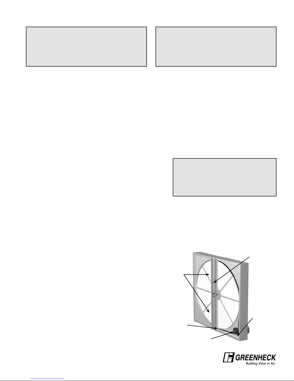
DRIVE BELT
Inspect the drive belt. Make sure the belt rides smoothly through the pulley and over the rim.
AIR SEALS
Check that the air seals located around the outside
of the wheel and across the center (both sides of
wheel) are secure and in good condition. Air seal
clearance is determined by placing a sheet of
paper, to act as a feeler gauge, against the wheel
face. To access seals, remove cassette access
panel. To adjust their seals, loosen all eight seal
retaining screws. These screws are located on
the bearing support that spans the length of the
cassette through the wheel center. Tighten the
screws so the air seals tug slightly on the sheet of
paper.
Replace cassette into ERM cabinet, plug in wheel
drive, replace access door and apply power.
Confirm that the wheel rotates freely at about
50-60 rpm.
ELECTRICAL CONNECTIONS
The electrical supply must be compatible with that shown on the wheel drive motor nameplate: voltage,
phase, and amperage capacity (see page 3 for specific requirements). Units are supplied with a receptacle
for the cassette plug and service box for wiring. Connect the ERM wiring directly to blower wiring or to
blower fan relay to power the ERM whenever the fan is in operation. All wiring must be properly fused and
conform to local and national electrical codes.
Do not operate the ERM for any extended period without airflow across the energy wheel as the drive motor
is cooled by the airflow.
MOUNTING
The ERM is shipped with a mounting kit, which contains four hanging brackets, fasteners and a separate
instruction sheet with parts list. These brackets will support the ERM in either the vertical or horizontal
position for design flexibility. A 3/8 in. x 3/4 in. hex head bolt is located at each corner of the ERM for
attaching these brackets. To hang the ERM:
Note: To reduce unit weight for handling purposes, the cassette may be removed from the cabinet (reduces
ERM-36 from 193 lbs. to 75 lbs., reduces ERM-52 from 330 lbs. to 110 lbs.).
1. To remove the cassette from the cabinet, remove the access panel and unplug the
wheel drive motor at the electrical receptacle in the cabinet.
2. Replace the access panel before mounting to insure squareness.
3. Remove the appropriate four bolts from the ERM and use to secure the brackets as
shown in Figure 1. These brackets are designed for 3/8 in. threaded hanging rods.
4. To reinstall the cassette in the mounted ERM cabinet, align
the cassette sliders with the channels in the cabinet and
slide the cassette in place. Replace access panel when
finished.
STORAGE
When a unit is not going to be in service for an extended amount of time, certain procedures should be
followed:
• Cover unit with tarp to protect from dirt and moisture (Note: do not use a black tarp as this will
promote condensation)
• Store unit in location which does not have vibration
If storage of unit is in a humid, dusty or corrosive atmosphere, rotate the fan and purge the bearings once a
month. Improper storage which results in damage to the unit or components will void the warranty.
IMPORTANT
ERM must be installed such that the energy
wheel cassette slides in and out of the cabinet
parallel to the floor.
START-UP
SAFETY CAUTION!
Use caution when removing access panels or other
unit components, especially while standing on a
ladder or other potentially unsteady base. Access
panels and unit components can be heavy and
serious injury may occur.
SAFETY DANGER!
Electric shock hazard. Can cause injury or death.
Before attempting to perform any service or
maintenance, turn the electrical power to unit to OFF.
Every installation requires a comprehensive start-up to ensure proper operation of the unit. As part of that
process, the following information must be recorded. Should an issue arise which requires factory assistance,
this important information will allow unit experts to provide quicker resolve. Qualified personnel should perform
start-up to ensure safe and proper practices are followed.
Unit Model Number ____________________________ (e.g. ERM-36H-15)
Unit Serial Number ____________________________ (e.g. 04C99999 or 10111000)
Energy Wheel Date Code ____________________________ (e.g. 0450)
Start-up date ____________________________ (MM/DD/YYYY)
Start-up Personnel Name ____________________________
Start-up Company ____________________________
Phone Number ____________________________
**WARNING**
Do not operate Energy Recovery Module
without duct filters or screens installed.
The filters and screens prevent the entry of
foreign objects such as leaves, birds, etc.
DIMENSIONAL DATA & SPECIFICATIONS
Model A B C D E F G H Voltage Hertz Phase Amps Motor
HP
Weight
Cabinet Cassette
ERM-36S-15 341/442 441/25 143/4177/8143/4121/2200-230/460 50/60 1 0.6 1/20 75 80
ERM-36H-15 341/442 441/25 143/4177/8143/4121/2200-230/460 50/60 1 0.6 1/20 75 80
ERM-36H-30 341/442 441/25 143/4177/8143/4121/2200-230/460 50/60 1 0.6 1/20 75 118
ERM-52S-15 501/2581/4603/461/2173/4177/8143/4121/2200-230/460 50/60 1 1.2 1/6 110 188
ERM-52H-15 501/2581/4603/461/2173/4177/8143/4121/2200-230/460 50/60 1 1.2 1/6 110 188
ERM-52H-30 501/2581/4603/461/2173/4177/8143/4121/2200-230/460 50/60 1 1.2 1/6 110 220
All dimensions shown are in inches.
CA
F
H
G
D
B
E
ROUTINE MAINTENANCE
Once the unit has been put into operation, a routine maintenance program should be set up to preserve
reliability and performance. Items to be included in this program are:
DATE DATE DATE DATE
______ ______ ______ ______
Energy Recovery Wheel
Check for cleanliness - clean if required oooo
Check belt for wear oooo
Check pulley, bearings, and motor oooo
INSTALLATION CLEARANCES
Provide proper clearance for cassette inspection, service or removal. Do not install ducting, piping or
wiring where it will interfere with cassette removal.
Model Inspection
or Service Removal
ERM-36 22 inches 42 inches
ERM-52 30 inches 58 inches
Storage .................................2
Electrical Connection .....................2
Mounting.................................2
Start-Up
Drive Belt . . . . . . . . . . . . . . . . . . . . . . . . . . . . . . . 3
AirSeals................................3
Dimensional Data & Specifications . . . . . . . . 4
Installation Clearances . . . . . . . . . . . . . . . . . . . . 4
Rountine Maintenance
Energy Recovery Wheel . . . . . . . . . . . . . . . . . . . 5
Routine Maintenance - continued
Energy Recovery Wheel Maintenance . . . . . . . . 5
Energy Recovery Wheel Access. . . . . . . . . . . . . 5
Removal of Segments . . . . . . . . . . . . . . . . . . . . . 5
Cleaning the Energy Recovery Wheel ........5
Energy Recovery Wheel Belt . . . . . . . . . . . . . . . 5
Energy Recovery Wheel Bearings ...........5
Parts List . . . . . . . . . . . . . . . . . . . . Backcover
Troubleshooting . . . . . . . . . . . . . . . Backcover
Warranty..................... Backcover
TABLE OF CONTENTS
Drive
Belt
Drive
Pulley
Label
showing
cassette
serial #
and
date code
Adjustable
Air Seals
Bearing
Support
23 4
FIGURE 1