INSTALLATION INSTRUCTIONS
PTO
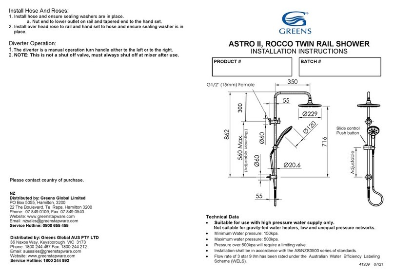
• Top Inlet at the diverter.
• Diverter is 41mm dia.
• Bottom bracket mount is adjustable with max 800mm Centres.
Install The 15mm Female Inlet Adaptor:
1. At pipe-out stage install a brass 15mm male wingback elbow (not supplied).
a. Remove the adaptor from the diverter.
i. NOTE: Loosen off the grub screw to ensure the O-rings are not cut
on the adaptor.
b. Note: The female inlet adaptor requires MAX 20mm thread from finished
wall.
c. Inlet is at the top.
d. CHECK: The height required with customer as there is no height
adjustment.
2. Cut the inlet thread to MAX 20mm from finished wall.
3. Install adaptor using a spanner or a 10mm Allen key.
a. Back edge of the adaptor to be level with the finished wall as shown.
Install Mounting Block For Bottom Bracket:
1. Mark out and install mounting block inline with the inlet to ensure rail will be
straight.
a. Note: For adjusting the bracket height, a locking screw is inside bracket.
To adjust use 5mm Allen key.
b. Must screw into a wooden stud or nog.
c. Wall anchor provided for masonry walls.
Installing Rail:
1. Install diverter with rail to inlet adaptor.
a. Lightly grease the O-rings on the inlet adaptor.
b. CHECK: The grub screws top and bottom are not projecting into the
bore. c. Sealant is required behind the diverter to wall for water seal
(not supplied
2. Install bottom bracket.
a. Back off grub screw enough for attaching to the mounting block.
b. Sealant is required behind the diverter to wall for water seal (not sup-
plied).
c. Install rail to the mounting block and tighten the grub screw.
i. To adjust bottom rail bracket height, back off grub screw inside
and tighten at height required using a 5mm Allen key.
3. Install overhead arm to top of diverter, position and tighten the nut.


