GreenTech RD1830 Series User manual

1
Intelligent Radar Level Transmitter
Programming Menu-RD1830 series
Greentech, Korea
www.greentechkor.com E-mail: info@greentechkor.com
Programming Menu RD1830 series
Brief Introduction :
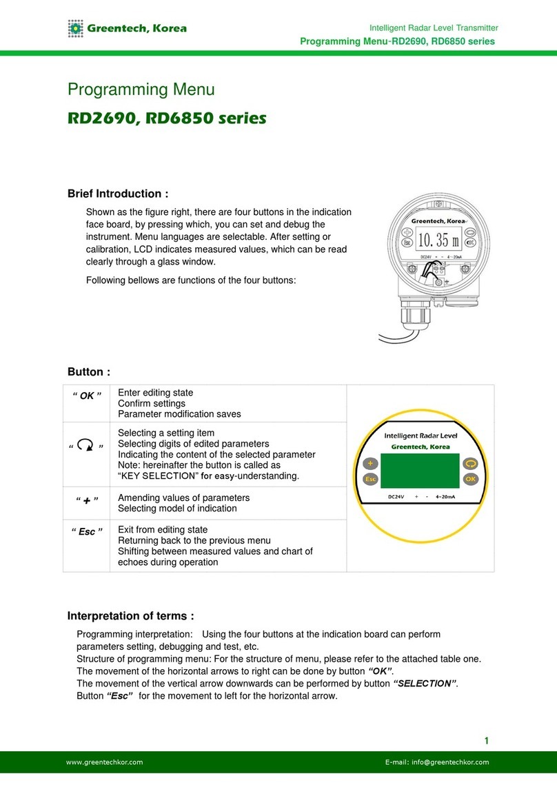
Shown as the figure right, there are four buttons in the indication
face board, by pressing which, you can set and debug the
instrument. Menu languages are selectable. After setting or
calibration, LCD indicates measured values, which can be read
clearly through a glass window.
Following bellows are functions of the four buttons:
Button :
“OK ”
Enter editing state
Confirm settings
Parameter modification saves
“
”
Selecting a setting item
Selecting digits of edited parameters
Indicating the content of the selected parameter
Note: hereinafter the button is called as
“KEY SELECTION” for easy-understanding.
“+”
Amending values of parameters
Selecting model of indication
“Esc ”
Exit from editing state
Returning back to the previous menu
Shifting between measured values and chart of
echoes during operation
Interpretation of terms :
Programming interpretation: Using the four buttons at the indication board can perform
parameters setting, debugging and test, etc.
Structure of programming menu: For the structure of menu, please refer to the attached table one.
The movement of the horizontal arrows to right can be done by button “OK”.
The movement of the vertical arrow downwards can be performed by button “SELECTION”.
Button “Esc”for the movement to left for the horizontal arrow.

2
Intelligent Radar Level Transmitter
Programming Menu-RD1830 series
Greentech, Korea
www.greentechkor.com E-mail: info@greentechkor.com
Submenu :
Basic setting: Basic setting includes the settings for basic parameters, lower position adjustment,
higher position adjustment, the character of the medium, damping time, signal threshold, output
mapping, calibration unit, calibration, setting length of probe, dead band, sensor label.
Indication: includes indicating content, LCD contrast.
Diagnosis: perform checking and test. Mainly include measuring peak value, measuring state,
select chart, ECHO GRAPH and simulation.
Service: including false echo, current output, reset, measuring unit, language, HART working mode,
copying sensor data, cipher, and deviation of distance.
Information: basic information includes type of sensor, series number, production date, version of
software.
Instrument in the running state press the "OK" button to enter programming state, display
programming main menu. Each parameter editor to finish, with "OK" button confirmation,
otherwise the editor is invalid. When done editing, press the esc key to exit programming state, to
return to running status. The editor at any time can press the esc key to give up programming,
exit parameters of programming state.
Editing method (character/ figure parameter programming): when entering character/ figure
programming state, the first digit of the edited parameter will become black, at this time, press
button “+” to change the character or figure until the required character or figure appear.
Press button “SELECTION”, character or figure will turns black in order, then edit them one by
one. When finish, press button "OK"for confirmation.
Optional parameters editing: optional parameter is defined as a plurality of selected parameters
in the editing item, which can selected by user.
Press button “SELECTION”, move the arrow the
position where the needed parameter is. Press button "OK" for confirmation.
Note: the figure at right top corner is menu number.

3
Intelligent Radar Level Transmitter
Programming Menu-RD1830 series
Greentech, Korea
www.greentechkor.com E-mail: info@greentechkor.com
1. Basic settings
1.1. Low position
adjustment:
Low position adjustment is for measuring range setting.
It determines the proportion of output current linearity corresponding
relationship together with high position adjustment. In main menu, when
the menu number is 1, press button OK, enter the submenu of basic
settings. LCD indicates as follows:
LOW POSITION ADJUSTMENT 1.1
0.00%
35.000m (d)
1.346m (d)
Press button OK, enter programming low position percentage, refer to the
previous stated character/figure parameter editing method in parameter
editing method to edit the percentage value and distance value. After
editing, press button OK for confirmation, or press button ESC for quitting
editing.
1.2. High position
adjustment:
High position adjustment is for measuring range setting. It determines the
proportion of output current linearity corresponding relationship together
with low position adjustment. When LCD indicates the menu number 1.1,
press button SELECTION, enter high position adjustment. LCD indicates
as follows:
HIGH POSITION ADJUSTMENT 1.2
100.00%
0.000m (d)
1.346m (d)
At this time, you can edit the high position adjustment with button OK.
1.3. Medium
properties:
When LCD indicates menu number 1.2, press button SELECTION, enter
medium properties editing. Medium properties menu is for selecting solid,
liquid or micro DK, thus further select material property to some other
factors affect the measurement. LCD indicates as follows:
MEDIUM PROPERTIES 1.3
LIQUID
MEDIUM PROPERTIES 1.3
LIQUID
SOLID MICRO DK
1.3.1
Level quick change: When select liquid or solid in the medium properties,
press button OK, enter quick
change menu. LCD indicates:
LEVEL QUICK CHANGE 1.3.1
YES
Press button OK again and enter quick change menu. LCD indicates as
follows:
LEVEL QUICK CHANGE 1.3.1
YES
NO
1.3.2.
Select the first wave: When select liquid or solid in medium properties,
while LCD indicates menu 1.3.1,
press key SELECTION to select the next menu and enter the first wave
selection menu. LCD indicates as follows:
SELECTING THE FIRST WAVE 1.3.2
NORMAL

4
Intelligent Radar Level Transmitter
Programming Menu-RD1830 series
Greentech, Korea
www.greentechkor.com E-mail: info@greentechkor.com
Press button OK again, enter the first wave selection menu, LCD indicates
as follows:
SELECTING THE FIRST WAVE 1.3.2
NORMAL LITTLE STRONGER
WEAKEN STRONGER
STRONGEST
There are five methods of the first wave selection by press button
SELECTION:
NORMAL: DO NOTHING FOR THE FIRST WAVE AMPLITUDE
(DEFAULT)
WEAKEN: THE FIRST WAVE AMPLITUDE WEAKEN 10dB
LITTLE STRONGER: THE FIRST WAVE STRENGTHEN 10dB
STRONGER: THE FIRST WAVE STRENGTHEN 20dB
STRONGEST: THE FIRST WAVE STRENGTHEN 40db
1.3.3.
(Liquid) Surface wave: When the medium is liquid, LCD indicates the
menu number 1.3.2, press button
SELCTION to select the next menu and enter the menu of surface wave,
LCD indicates as follows:
SURFACE WAVE 1.3.3
NO
Press button OK again and enter the menu of surface wave, LCD indicates
as follows:
SURFACE WAVE 1.3.3
YES
NO
1.3.3.
(Solid) big stack angle: When the medium is solid, LCD indicates the
menu number 1.3.2, press button SELCTION to select the next menu and
enter the menu of big stack angle, LCD indicates as follows:
STACK ANGLE BIG 1.3.3
NORMAL
Press button OK again and enter stack angle big selection menu, LCD
indicates as follows:
STACK ANGLE BIG 1.3.3
YES
NO
1.3.4.
(Liquid) Foam: When LCD indicates the menu number 1.3.3, press button
SELECTION select the next menu and enter form menu, LCD indicates as
follows:
FOAM 1.3.4
NO
Press button OK again, enter form selection menu, LCD indicates as
follows:
FOAM 1.3.4
YES
NO
1.3.4.
(Solid) Foam: When LCD indicates the menu number 1.3.3, press button
SELECTION select the next
menu and enter heavy dust selection menu, LCD indicates as follows:
HEAVY DUST 1.3.4
NO

5
Intelligent Radar Level Transmitter
Programming Menu-RD1830 series
Greentech, Korea
www.greentechkor.com E-mail: info@greentechkor.com
Press button OK again, enter heavy dust selection menu, LCD indicates
as follows:
HEAVY DUST 1.3.4
YES
NO
1.3.5.
DK small value: When LCD indicates 1.3.4, press button OK and enter
DK adjustment menu, LCD indicates as follows:
DK VALUE SMALL 1.3.5
NO
Press button OK again and enter liquid DK adjustment menu, LCD
indicates as follows:
DK VALUE SMALL 1.3.5
YES
NO
Press button SELECTION to select “YES” and set the measurement when
DK value is small. LCD indicates as follow, then input accurate empty cans
empty high value. This value will be used to judge the position of the tank
bottom in order to decrease the reflection from the bottom, LCD indicates
as follows:
DK VALUE SMALL 1.3.5
YES. DISTANCE WHEN TANK IS EMPTY 3.00m
1.3.6.
(Liquid) Guided wave pipe setting: When LCD indicates the menu
number 1.3.5, press button SELECTION and enter the guided wave pipe
setting menu, LCD indicates as follows:
GUIDED WAVE PIPE MEASUREMENT 1.3.6
NO
Press button OK, enter guided wave pipe measurement selecting menu,
LCD indicates as follows:
GUIDED WAVE PIPE MEASUREMENT 1.3.6
YES
NO
Press button SELECTION and select “YES”, and press button OK to enter
guided wave pipe diameter setting menu, LCD indicates:
GUIDED WAVE PIPE MEASUREMENT 1.3.6
GUIDED WAVE PIPE DIAMETER 0000mm
Note: guided wave pipe setting can keep valid only when a guided wave
pipe is mounted.
1.3.7
Micro DK: When select the medium properties as micro DK, press button
OK to enter micro DK setting, LCD indicates as follows:
MICRO DK SETTING 1.3.1
DISTANCE WHEN TANK EMPTY 10.00m
MEDIUM LEVEL 0.00m
DK 0.020m(d) 1.00
When select medium property as micro DK, it is used for the case, when
the dielectric constant is less than 1.4, the echoes directly from medium
surface is very weak, or the measurement cannot be performed. With the
method of bottom reflection the medium level can be measured. Then you
have to input two values of the parameters listed below:
1. distance when tank empty.
2. medium actual level value or the dielectric constant of the medium to be
measured, these two values are related, it is ok to input one of them. The
accuracy of the mentioned above values can directly influence the
accuracy of the measurement result.

6
Intelligent Radar Level Transmitter
Programming Menu-RD1830 series
Greentech, Korea
www.greentechkor.com E-mail: info@greentechkor.com
Note: Please carefully choose “MICRO DK”. It is not suitable for the most
of measurement. After selecting MICRO DK, according to the situation of
echoes, the instrument will adopt using direct echo method or bottom
reflection method to get the measurement result.
1.4 Damping time:
Damping time: When LCD indicates the menu number 1.3, press button
SELECTION, enter damping time setting menu, LCD indicates as follows:
DAMPING TIME: 1.4
6S
Press button OK, enter parameter edit mode. Press button “+” to set the
figures. Press button SELECTION to select the figure digit to be edited.
Then press button OK for confirmation.
1.5. Signal
threshold:
signal threshold is used for the basic line for setting output linearity. When
LCD indicates
the menu number 1.4, press key SELECTION to enter output mapping
editing menu, LCD indicates as follows:
SIGNAL THRESHOLD 1.5
25mV
Press button OK and enter editing mode, press button “+” to set figures.
Press button OK for confirmation after editing.
1.6. Output
mapping:
Output mapping: output mapping is used for selection between
nonlinearity output mapping and linearity mapping set from a host
computer. When LCD indicates the menu number 1.5, press button
SELECTION to enter output mapping editing menu. LCD indicates as
follows:
OUTPUT MAPPING 1.6
LINEARITY
Press button OK to enter parameter selection mode. Press button
SELECTION to select linearity or other selectable mapping modes, for
example, linearity, horn, etc. Press button OK for confirmation after editing.
When select linearity output mapping, it will be used for selecting different
units.
1.7. Calibration
unit:
Calibration unit: When LCD indicates the menu number 1.6, press button
SELECTION to enter calibration unit setting menu. LCD indicates as
follows:
CALIBRATION UNIT 1.7
HEIGHT m
Press button OK to enter parameter selection mode, then press button
SELECTION for confirmation, and select the corresponding unit, press
button OK for confirmation. When select linearity output mapping, it will be
used for determining concrete mapping relationship.
1.8. Calibration:
Calibration: When LCD indicates the menu number 1.7, press button
SELECTION to enter calibration setting menu. LCD indicates as follows:
CALIBRATION 1.8
0%= 0.00 m
100%= 0.00 m
Press button OK, the area of parameter become black, press button
SELECTION to set the decimal point, press button OK for confirmation.
The parameters area corresponds to 0% become black. Press button
SELECTION and button “+” for setting parameters.
Then press button OK for confirmation. For setting the values
corresponding to 100%, the steps and methods are the same.

7
Intelligent Radar Level Transmitter
Programming Menu-RD1830 series
Greentech, Korea
www.greentechkor.com E-mail: info@greentechkor.com
1.9. Setting
measuring range:
Setting measuring range: In order to get correct measuring result,
measuring range has to be set.
When LCD indicates the menu number 1.8, press button SELECTION to
enter measuring range setting menu. LCD indicates as follows:
MEASURING RANGE SETTING 1.9
00.000m(d)
Press button “OK”, the corresponding parameters turn black, press button
SELECTION or button “+” for setting parameters, then press button OK for
confirmation.
1.10. Dead zone:
Dead zone: When there is a fixed obstacle close to the propagator, it
interferes the measurement, when the maximum medium level cannot be
up to the obstacle, using dead zone setting can avoid measurement
mistake.
When LCD indicates the menu number 1.9, press button SELECTION to
enter dead zone setting menu. LCD indicates as follows:
DEAD ZONE 1.10
0.300m(d)
Press button OK, the corresponding parameters turn black, press button
SELECTION or button “+” for setting parameters, and press button OK for
confirmation.
1.11. Sensor tag:
When LCD indicates the menu 1.10, press button SELECTION to shift the
menu to sensor tag indicating item, LCD indicates as follows:
SENSOR TAG 1.11
SENSOR

8
Intelligent Radar Level Transmitter
Programming Menu-RD1830 series
Greentech, Korea
www.greentechkor.com E-mail: info@greentechkor.com
2. Indications:
This function is used for editing with indication. When LCD indicates main
menu, press button SELECTION
to move the arrow to indicating item. LCD indicates as follows:
BASIC SETTING 2
INDICATION
DIAGNOSE
SERVICE
MESSAGE
Press button OK to enter editing with indication.
2.1. When enter
editing with
indication, LCD
indicates as
follows:
INDICATING CONTENT 2.1
DISTANCE
When the current indicated parameter is distance, i.e., the instrument
indicates measured distance. Press button Ok to enter editing mode. LCD
indicates as follows:
INDICATING CONTENT 2.1
NO WORKING MAPPING PERCENTAGE
DISTANCE CALIBRATED VALUE
MEDIUM LEVEL CURRENT
PERCENTAGE
When press button SELECTION to move the arrow to the required item
and press button OK for confirmation. After editing, press button “ESC”,
exit indication programming and go back to the previous menu.
2.2. LCD contrast
adjustment:
When LCD indicates the menu number 2.1, press button SELECTION to
enter LCD contrast menu. LCD indicates as follows:
LCD CONTRAST 2.2
ADJUSTMENT?
Press button OK to enter adjustment mode.
LCD CONTRAST 2.2
Press button SELECTION or button “+” to increase or decrease contrast,
press button OK for confirming the operation and save the setting.

9
Intelligent Radar Level Transmitter
Programming Menu-RD1830 series
Greentech, Korea
www.greentechkor.com E-mail: info@greentechkor.com
3. Diagnose:
When LCD indicates main menu, press button SELECTION to move the
diagnosis of the arrow, LCD indicates as follows:
BASIC SETTING
INDICATION
DIAGNOSE
SERVICE
INFORMATION
The function of diagnose can be used for testing the working conditions of
the instrument and other parts and debugging the system. Press button
OK to enter the function of diagnose.
3.1. Peak
measurement:
Peak indication is the indication of the distance peak during the
measurement. This parameter can be deleted with the reset under item
4.4 of service menu. LCD indicates as follows:
MEASUREMENT PEAK 3.1
MINIMUM DISTANCE VALUE 0.000 m (d)
MAXIMUM DISTANCE VALUE 2.109 m (d)
3.2. Measurement
mode:
When LCD indicates the menu number 3.1, press button SELECTION to
enter the next diagnose mode. LCD indicates as follows:
MEASUREMENT MODE 3.2
MEASUREMENT RELIABILITY: 20 dB
SENSOR MODE: OK
3.3. Curve
selection:
When LCD indicates the menu number 3.2, press button SELECTION to
enter graph indication mode. LCD indicates as follows:
CURVE SELECTION 3.3
ECHO GRAPH
When need to select other curves, press button OK to enter curve
selection menu. LCD indicates as follows:
CURVE SELECTION 3.3
ECHO GRAPH
FALSE ECHO GRAPH
OUTPUT TREND CURVE
Press button SELECTION to move the arrow to the point which is required
to be indicated along the curve, press button OK for confirmation.
3.4. ECHO GRAPH:
When LCD indicates the menu number 3.3, press button SELECTION to
make LCD indicate the selected curve. The function of curve zoom can be
used to amplify the curve along the axes of time and amplitude so that it to
be read clearly. When LCD indicates graph, press button OK to enter
curve zoom editing menu. LCD indicates as follows:
CURVE ZOOM 3.4
ZOOM ALONG AXIS X
ZOOM ALONG AXIX Y
NO ZOOM
Press button SELECTION to move the arrow for selecting zoom direction
or no zoom, press button OK
for confirmation. When select zoom along axis X, press button
SELECTION to move the start point to the place where it is needed, press
button OK for confirmation. Press button SELECTION again to move the
end point to the place where it is needed, press button OK for
confirmation. At the time, the area selected is amplified up to the whole
screen. Press button “ESC” to exit the curve indication.

10
Intelligent Radar Level Transmitter
Programming Menu-RD1830 series
Greentech, Korea
www.greentechkor.com E-mail: info@greentechkor.com
3.5. Simulation:
Simulation is to simulate output 4-20mA, which is used to if output of
instrument is normal.
Meanwhile, it can be used for system debugging. When LCD indicates the
menu number 3.4, press button
SELECTION to enter simulation mode. LCD indicates as follows:
SIMULATION 3.5
START SIMULATION
Press button OK for confirm simulation, LCD indicates as follows:
SIMULATION 3.5
PERCENTAGE
CURRENT
DISTANCE
Press button SELECTION to select current output mapping mode, press
button OK for confirming entering the set menu. After setting the figures,
press button OK for confirmation. At this time, the set value of the current
output corresponds to the current value.
Note: Three alternative menus illustration percentage: output current
according to the given percentage. For example, 100% corresponds to
20mA, 0% corresponds to 4mA. Current: output current according to the
given current value. For example, 16.6mA corresponds to 16.6mA.
Distance: output current according to distance value (this relationship
between this value and the current value can be determined by 1.1. low
position adjustment, 1.2. high position adjustment and 1.5. output
mapping).

11
Intelligent Radar Level Transmitter
Programming Menu-RD1830 series
Greentech, Korea
www.greentechkor.com E-mail: info@greentechkor.com
4. Service:
The menu of service contains more professional functions, which will be
used for people who have been trained. Main functions are for false echo
setting, time variable gain, reset and parameters storage, etc. When LCD
indicates main menu, press button SELECTION to move the arrow to the
item of service. LCD indicates as follows:
BASIC SETTING
INDICATION
DIAGNOSE
SERVICE
MESSAGE
4.1. False echo:
When there is a fixed obstacle which is interfering the measurement, you
can use the function of false echo setting to overcome its interference.
When LCD indicates the main menu and the menu number is 4, press
button OK to enter service submenu, LCD indicates as follows:
FALSE ECHO 4.1
AMEND IT?
Press button OK, LCD indicates as follows:
FALSE ECHO 4.1
DELETE
UPDATE
NEW CREATING
EDIT
When you want to update or generate a false ECHO GRAPH, press button
SELECTION to move the arrow to the needed item, then press button OK
for confirmation. LCD indicates as follows:
FALSE ECHO 4.1
UPDATE/NEW CREATING 1.000mm
LCD asks to input the real echo distance value, after inputting the distance
value, press button OK for confirmation. LCD indicates waiting, and then
the instrument enters the state of false echo setting. When it finishes, LCD
goes back to false echo setting menu.
Note: the difference between “updating false ECHO GRAPH” and
“generating false ECHO GRAPH” is that "new false echo curve" is to edit a
false echo curve; "Update false echo curve" is the original before false
echo curve based on the edit update.
When you want to delete the false ECHO GRAPH, press button
SELECTION to move the arrow to the needed item, and then press button
OK for confirmation. LCD asks waiting. The instrument is processing
deleting the false echo. After finish, LCD goes back to false echo setting
menu.
When you want to edit the false ECHO GRAPH, press button SELECTION
to move the arrow to the needed item and then press button OK for
confirmation. This function can edit or modify the created false echo to
adapt the request of special working conditions. After entering the false
echo edition, LCD indicates as follows:
(Note: this menu needs professional person for operation):
FALSE ECHO EDITION
START POINT 1.00 AMPLITUDE 1300m(d)
END POINT 2.00 AMPLITUDE 1500m(d)
Two points can be edited a time, the start point and the end point are the
coordinates for the curve which is needed to be edited. The following
corresponding value of amplitude is the value to be edited (Note: when
input or alter the distance coordinates, the corresponding amplitude will

12
Intelligent Radar Level Transmitter
Programming Menu-RD1830 series
Greentech, Korea
www.greentechkor.com E-mail: info@greentechkor.com
automatically be updated according to the currently saved value which will
act as reference for amplitude modification).
When the modification for the two pairs of coordinates is finished, press
button OK for confirmation of the modification. The instrument will
automatically link the two points and create a new false ECHO GRAPH,
substitute for the old curve. Press button OK for confirmation, LCD will
indicate the false ECHO GRAPH after the modification this time for
reference.
And then press button ESC, LCD goes back to the edition interface for
further edition. When the false echo edition reach to the request of the
working conditions, press button ESC again, LCD exits false echo edition
menu. Then LCD indicates as follows:
FALSE ECHO EDITION
SAVE IT?
Press button OK for saving for what have been modified above. Press
button ESC for giving up the current modification.
4.2. Output mode:
This setting is for setting current output mode. When LCD indicates the
menu number 4.1, press button SELECTION, LCD indicates as follows:
CURRENT OUTPUT
OUTPUT MODE: 4-20mA
FAULT MODE: NO CHANGE
MINIMUM CURRENT: 4mA
When LCD indicates current output mode for selection of 4-20mA or 20-
4mA, 4-20mA means that low medium level corresponds to 4mA, high
medium level corresponds to 20mA: 20-4mA means that low medium level
corresponds to 20mA, high medium level corresponds to 4mA.
When LCD indicates current output selection menu 4.2, press button
SELECTION to move the arrow to the output mode and press button OK
for confirmation, then LCD indicates as follows:
OUTPUT MODE 4.2
NO CHANGE
20.5mA
22.0mA
4.0mA
Press button SELECTION to select the setting you need, press button OK
for confirmation.
Minimum current is used for selecting the minimum current as “4mA” or
“3.8mA”. When LCD indicates current output selection menu 4.2, press
button SELECTION to move the arrow to “minimum current”, and then
press button OK for confirmation. LCD indicates as follows:
MINIMUM CURRENT 4.2
3.9mA
4mA
Press button SELECTION for the selected setting, press button OK for
confirmation.
4.3. Reset the
function of reset is
used for the reset
of finished
parameters.
There are four reset functions: basic setting, factory setting, peak
measurement and accumulated flow. Basic setting is to recover different
kinds of parameters in basic setting items back to factory default setting.
Factory setting is to recover all parameters back to factory fault setting.
Measurement peak setting is to clear the peak measurement in the
diagnosis. Reset for accumulated flow is to clear the accumulated flow
when the instrument is used for measuring the flow of open channel.
When LCD indicates current output (menu number 4.2), press button
SELECTION to enter reset function, LCD indicates as follows:

13
Intelligent Radar Level Transmitter
Programming Menu-RD1830 series
Greentech, Korea
www.greentechkor.com E-mail: info@greentechkor.com
RESET 4.3
SELECTING RESET
Press button OK to enter the reset selection menu, select the
corresponding reset function item for resetting according to the needs.
4.4. Measuring
unit:
There are two choices of measuring units for users, one is the metric
system, the other is imperial system. When LCD indicates menu number
4.3, press button SELECTION to enter measuring unit setting menu, LCD
indicates as follows:
MEASURING UNIT 4.4
M (d)
Press button OK to enter the measuring unit selection menu, select the
unit according to the needs.
4.5. Language:
There are four choices of languages for users, they are Chinese, English,
French and Italian.
When LCD indicates measuring unit menu number 4.4, press button
SELECTION to enter language setting, and LCD indicates as follows:
LANGUAGE 4.5
ENGLISH
Press button OK for entering the languages selection menu and select the
language you need.
4.6. HART mode:
When two or more than two instruments are connected to a computer with
HART communication interface, use this function to set the instrument into
multiple working mode. When LCD indicates language menu number 4.5,
press button SELECTION to enter working mode menu. LCD indicates as
follows:
HART WORKING MODE 4.6
STANDARD
ADDRESS 0
Press button OK to enter HART working mode setting interface, LCD
indicates as follows:
HART WORKING MODE 4.6
STANDARD MULTIPLE
Press button SELECTION to select standard or multiple working modes.
The address of the instrument is “0” when select standard working mode.
When select HART working mode as multiple, LCD indicates as follows:
HART WORKING MODE 4.6
ADDRESS 0
POWER SUPPLY 4mA
The address can be changed from 1-15. Working current 4mA and 8mA
can be selected. Press button OK for confirmation.
4.7. Copy sensor
data:
copy sensor data, there are two submenus: from “COPY FROM SENSOR”
to “COPY TO SENSOR”. This function is used for the safety of the
instrument parameters. When technician finish setting the instrument
parameters according to the working conditions, you can use the function
of “COPY FROM SENSOR” to protect or save the set parameters.
Once the parameters are altered accidently, you can use the function of
“COPY TO SENSOR” to recover them.
When LCD indicates HART working mode submenu number 4.6, press
button SELECTION to enter “copy sensor data functions”. LCD indicates
as follows:
COPY SENSOR DATA 4.7
COPY TO SENSOR?

14
Intelligent Radar Level Transmitter
Programming Menu-RD1830 series
Greentech, Korea
www.greentechkor.com E-mail: info@greentechkor.com
Press button OK, LCD indicates as follows:
COPY SENSOR DATA 4.7
COPY FROM SENSOR
COPY TO SENSOR
Press button SELECTION to select the menu you need, and press button
OK for confirmation and perform the function.
4.8. Password:
Password is used for the safety of the parameters. Once the function is
actuated, you have to input the password every time when you want to
change a parameter.
When the right passwords are input, the protection function will be
cancelled. Then you can modify the parameters.
When LCD indicates menu number 4.7, press button SELECTION to enter
the password function. LCD indicates as follows:
PASSWORD ACTUATE IT? 4.8
Or PASSWORD CANCELL IT? 4.8
Press button OK to actuate password function and set password or cancel
it.
4.9. Distance
offset:
Distance offset is used for modifying the measurement error, which is the
difference between actual distance and the indicated distance.
When LCD indicates menu number 4.8, press button SELECTION to enter
distance offset menu. LCD indicates as follows:
DISTANCE OFFSET 4.9
+0.000m (d)
Press button OK for confirmation, then press button “+” and button
SELECTION to set offset. Finally press button OK for confirmation.
Echo graph indication steps are as follows:
Method 1:
1. Press button OK to enter the programming state, LCD indicates program main menu
2. Select submenu: press button SELECTION to move the arrow to the diagnosis submenu 3, the
number “3” is indicated at the right upper corner of the screen.
3. Press button OK for confirmation. Enter the diagnosis submenu 3.1 for indicating measurement
peak: minimum distance and maximum distance.
4. Press button SELECTION to next programmable item for indicating measurement state 3.2:
measurement reliability, sensor state:
5. Press button SELECTION again, enter selecting curve submenu 3.3.
6. Press button OK, enter parameters selection menu:
7. Press button SELECTION to move the arrow to select “ECHO GRAPH”, press button OK for
confirmation.
8. Press button SELECTION for indicating ECHO GRAPH 3.4.
9. Press button OK to enter curve zoom menu.
10. Press button SELECTION to zoom at axis X, press button OK for confirmation.
11. Press button SELECTION to move “the start point” to the place or point you need, press button
ESC for confirmation.
12. Press button SELECTION to move “the end point” to the place or point you need, press button OK
for confirmation. At this time, the selected curve has been magnified up to the whole screen.
13. Press button ESC continuously until the instrument go back to operation state.
Method 2:
Under main menu, press button ESC directly.
This is shortcut for indicating the ECHO GRAPH.

15
Intelligent Radar Level Transmitter
Programming Menu-RD1830 series
Greentech, Korea
www.greentechkor.com E-mail: info@greentechkor.com
Attached Diagram

16
Intelligent Radar Level Transmitter
Programming Menu-RD1830 series
Greentech, Korea
www.greentechkor.com E-mail: info@greentechkor.com
Table of contents
Other GreenTech Transmitter manuals
Popular Transmitter manuals by other brands

Endress+Hauser
Endress+Hauser Mycom S CPM 153 operating instructions

ADEMCO
ADEMCO 5817CB Installation and setup guide

Monacor
Monacor JTS TG-10STX 1 instruction manual

HETRONIC
HETRONIC NOVA XL quick start guide

Siemens
Siemens SITRANS P 7MF4232 operating instructions

Endress+Hauser
Endress+Hauser AT1000 AT1 operating instructions