7MF4232 Operating Instructions
5
C79000-B5676-C92-01
1 Technical Description
1.1 Range of Application
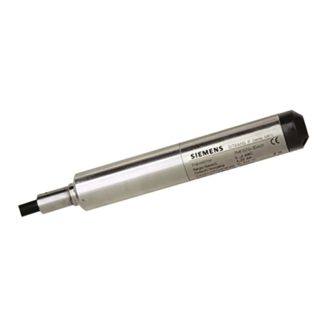
The Smart version of the SITRANS P transmitter measures the absolute pressure of non-aggressive and
aggressive gases, steam and liquids.
Measuring spans between 8.3 mbar and 30 bar are possible. The output signal is a load-independent
direct current of 4 to 20 mA which is linearly proportional to the absolute pressure.
Transmitters with intrinsic safety and flame--proof enclosure protection type can be used in areas where
there is an explosion hazard (zone 1). The certificates of conformity satisfy the European standard
(CENELEC) the American standard (FM) or the Canadian standard (CSA).
The transmitters are available with various types of chemical seal for special applications, e.g. measuring
high viscous substances.
1.2 How it works
The pressure is transferred via the isolating diaphragm (2, fig. 1.1) and the liquid filling (3) to the silicon
absolute pressure sensor (4) and its measuring diaphragm distorted. Four doped piezo-resistors in bridge
circuit in the measuring diaphragm change their resistance as a result. This change in resistance causes
a bridge output voltage proportional to the input pressure which is transformed through a measuring
amplifier (11) in an analog-digital converter (12) into a digital signal. The measuring signal is evaluated
by a microcontroller (13), corrected with respect to linearity and temperature behavior and transformed
by a digital-analog converter (14) into the output current 4 to 20 mA.
The measuring cell-specific data and the data for parameterization of the transmitter are stored in a
non-volatile EEPROM.
The cable termination point and the electronics’ side are arranged opposite.
The transmitter is parameterized with a PC/laptop or HARTR-Communicator. The PC/laptop is
connected to the two-wire circuit via the HARTR-Modem. The signals necessary for communication
accordingtotheHARTRprotocol, Revision 5.1, are superimposed on the output current according to the
frequency shift keying method (FSK, Frequency Shift Keying).
The following parameters can be set or their current settings interrogated:
- Measuring point number
- Measuring point description
-Text
- Upper limit of output signal
- Measuring limit
- Transmitter design (e.g. materials)
- Measuring range *
- Engineering unit *
- Measured value in mA, % or engineering units *
- Damping *
- ”Loop check” function *
- Output current in the event of an error *
- Pushbutton and/or function disable *
In addition to the parameterization with a PC/laptop or HARTR-Communicator (see Figure 1.2) the start
of scale and full scale can be ”fixed” on the transmitter with three external pushbuttons; the parameters
marked with*can be set directly on the transmitter using the digital display without opening the housing.

