GreenValley LiAir 220N User manual

LiAir 220N User Guide • GreenValley International Inc.
Page 1
––––––
LiAir 220N
UAV LIDAR System
User Guide
COPYRIGHT © 2017-2021 GreenValley International Inc.

LiAir 220N User Guide • GreenValley International Inc.
Page 2
GreenValley International Inc. (GVI) reserves all right for final explanation, and at its
sole discretion, to change, modify, and remove portions of this document.
No Part of this document may be reproduced or transmitted in any form or by any
means, electronic, mechanical, photocopying, recording, or otherwise, without prior
written permission of GreenValley International Inc.
GreenValley International Inc.
2120 University Ave. Ste. 210
Berkeley, CA. 94706
USA
+1 510.345.2899
info@greenvalleyintl.com
www.greenvalleyintl.com

LiAir 220N User Guide • GreenValley International Inc.
Page 3
About This Guide
This document is a general introduction and operation guide for GVI’s LiAir 220N lightweight UAV
LIDAR mapping/survey systems.
As we continue to update and improve the product, you may find some
differences between the contents of this document and your LiAir 220N
system. We will diligently update this guide as the product changes.
Please check with GVI for the latest release of this guide and contact GVI support at
suppprt@greenvalleyintl.com if you have any questions.

LiAir 220N User Guide • GreenValley International Inc.
Page 4
Content
1.
Read This First
................................................................................................................ 5
2.
LiAir 220N System
......................................................................................................... 6
2.1 About .......................................................................................................................................6
2.2 System Basics...........................................................................................................................6
2.3 System Principles.....................................................................................................................6
2.4 Technical Specification............................................................................................................7
2.5 LiAir 220N System Components .............................................................................................8
2.5.1 Laser Scanner ............................................................................................................................................... 8
2.5.2 Position and Orientation System (POS) ..................................................................................................... 9
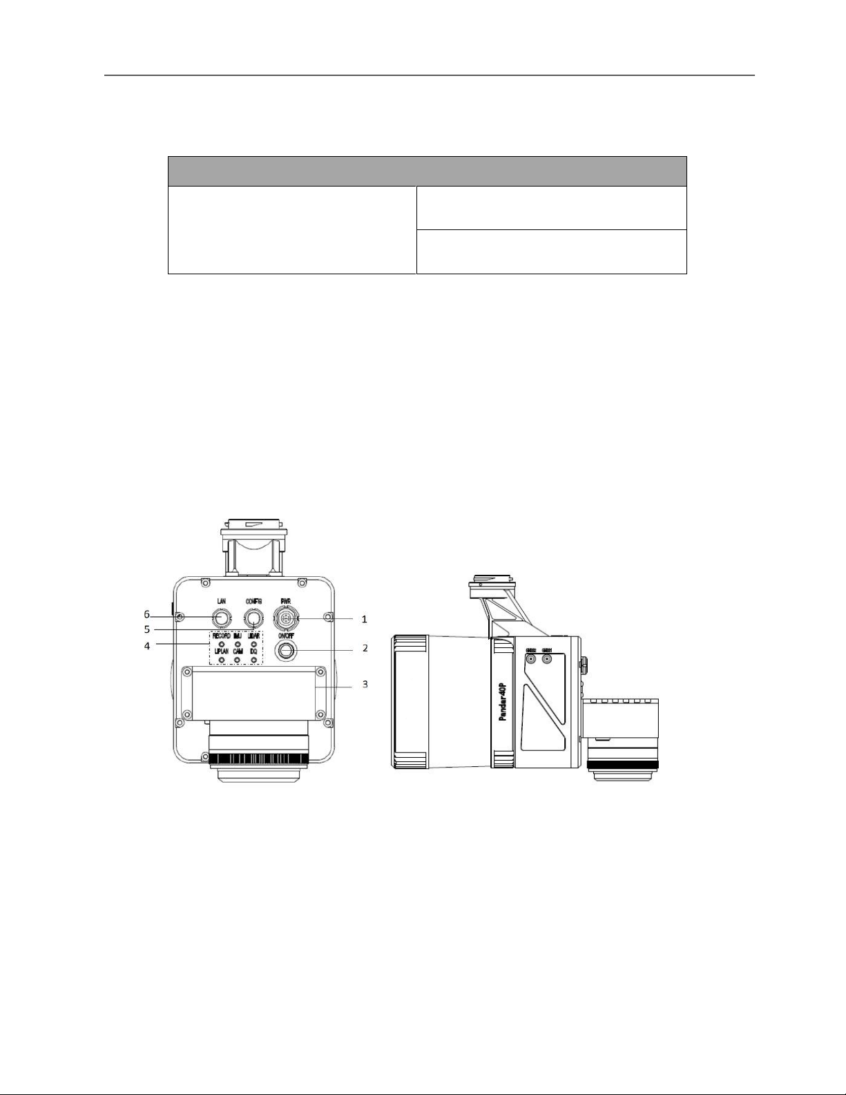
2.5.3 Control and Storage Unit .......................................................................................................................... 10
2.5.4 Integrated Camera (Optional)................................................................................................................... 13
3.
Equipment Setup and Operation Procedure
.............................................................. 13
3.1 Assemble and install LiAir 220N Payload Mounting Kit ......................................................13
3.2 Set up GNSS Base Station .....................................................................................................13
3.3 LiAir 220N Setup and Operation (DJI M300) .......................................................................16
4. Data Download
............................................................................................................... 20
4.1 Download LiAir 220N Data ...................................................................................................20
4.2 Download Base Station Data ................................................................................................21
4.3 Download Camera Data ........................................................................................................21
5. Data Processing
.............................................................................................................. 22
5.1 Project Folder Structure ........................................................................................................22
5.2 Data Post-processing ............................................................................................................24
5.2.1 Open Project .............................................................................................................................................. 24
5.2.2 Select and Configure Parameters ............................................................................................................. 25
5.2.3 Georeferencing Point Cloud Data ............................................................................................................ 31
5.2.4 Data Quality Assessment........................................................................................................................... 33
6.
Special Notes
............................................................................................................... 42

LiAir 220N User Guide • GreenValley International Inc.
Page 5
1. Read This First
Important Notices
STOP! PLEASE READ THIS SECTION CAREFULLY BEFORE USING THE
PRODUCT!
LiAir 220N systems use Class 1 (IEC60825-1:2014) eye-safe laser sensors. If you have any
concerns, please contact GVI for details.
System operator must be at least 18 years old.
Tampering with the product is strictly prohibited and will void the Product Warranty. Any
repair, modification, or upgrade must be performed by GVI technician or authorized service
provider.
Do NOT use any power supply outside the specified voltage range (12~24 V, 1.1A@24VDC).
Incorrect voltage supply may cause permanent damages to the integrated instruments and
other hazards. Damage caused by the use of an unauthorized power supply are not covered
by the Product Warranty.
STOP using the product and contact GVI support immediately, if there is any visible damage
or if persistent system warnings or alarms are observed. Failure to do so may result in
permanent damage to the LiAir 220N system.
This product is NOT water-proof. Do NOT operate in rain or snow. Water damage is NOT
covered by the Product Warranty.
This product is a high-precision mapping and surveying instrument that must be handled
with care. Damage caused by improper handling of the product are not covered by the
Product Warranty.
Properly disconnect all batteries, antennas, and cables after use.
This product should by stored and transported in the protective case provided with the LiAir
220N at the time of purchase or in a productive case authorized for use by GVI.
Clean the product thoroughly after each use. Do NOT use water.
When not in use, store LiAir 220N system and accessories in a cool and dry environment.

LiAir 220N User Guide • GreenValley International Inc.
Page 6
There may be additional notices and warning in placed throughout
part this document. Read each notice and warning carefully and please
follow the instructions.
2.LiAir 220N System
2.1 About
LiAir 220N UAV-LIDAR system is a light-weighted (2.0 kg incl. camera) and 3D surveying and mapping
instrument designed to be mounted to multi-rotor aerial platforms (DJI M300 & DJI M600). LiAir 220N
provides accuracy point cloud data for users in various industries including topographic surveying,
forestry, vegetation management, power line inspection, and many more. For additional information
on LiAir 220N, please contact GVI at info@greenvalleyintl.com.
2.2 System Basics
The LiAir 220N system integration is comprised of multiple technologies, including:
➢Laser Scanner (LIDAR sensor)
➢GNSS (Global Navigation Satellite System)
➢IMU (Inertial Measurement Unit)
➢System Control and Storage Unit
➢Power Supply and Management Unit
The GNSS unit and IMU unit together form what is often referred to as
the LiAir 220N’s POS Module.
2.3 System Principles
➢In operation, the System Controller receives and executes operational commands that control
the collection of data by each of the LiAir 220N’s integrated sensors and measurement
devices.
➢The POS Module (GNSS and IMU) determines LiAir 220N’s position and attitude at any given
point in time. This time-series position and attitude data is commonly referred to as the LiAir
220N’s trajectory or POS data.

LiAir 220N User Guide • GreenValley International Inc.
Page 7
➢The precise 3D coordinates of each data (LiDAR) point measured by the LiAir 220N’s Laser
Scanner are registered together to a common coordinate system and georeferenced using
the POS data.
➢LiAir 220N data are saved to the System Control and Storage Unit and can be downloaded
from the device after data collection has been stopped.
2.4 Technical Specification
Table 1. LiAir 220N Ultralight Specifications
LiAir 220N SPECIFICATIONS
Key Parameters
Weight
2.0kg (Incl. camera)
Scan Range
200 m @ 10% reflectivity
System Accuracy
± 5 cm
Voltage
12~24 V, 1.1A @ 24 VDC
Effective Scan Rate
720,000 points/s (Last or strongest return)
Working Temperature
0℃~40℃
Storage Temperature
-10℃~60℃
Dimensions
234 * 118* 181 mm
LIDAR Unit
Wavelength
905nm
Field of View
360°(horizontal) ×40° (vertical)
Eye-safe Laser Sensors
Class 1 (IEC60825-1:2014) (Safe for Eye)
Range Accuracy
2cm
# of Lines
40
Horizontal Resolution
Vertical Resolution
0.2°- 0.4° (horizontal)
0.33° -6°(vertical)
Scan Rate
720,000 points/s ( Last or strongest return)
1440,000 points/s (dual return)

LiAir 220N User Guide • GreenValley International Inc.
Page 8
2.5 LiAir 220N System Components
2.5.1 Laser Scanner
The Hesai Pandar40P is the LIDAR sensor integrated into the LiAir 220N Ultralight system. The LiDAR
sensor transmits an ultrashort pulse of NIR energy that strikes objects within the Laser Scanner’s field
of view and reflects back to the Laser Scanners receiver as a light echo. By measuring the amount of
time that has elapsed between signal transmission and signal reception (detection), the distance
from the laser scanner to the reflecting object can be determined.
As shown below, the Hesai Pandar40P has a FOV of 360° horizontally and 40° vertically. Note that
the effective detecting distance of the Hesai Pandar40P varies based on where the object is within
the FOV. The closer to the edge of the FOV, the shorter the effective detecting distance is. The closer
to the center of the FOV, the further the effective detecting distance.
Figure 1. LiAir 220N Product
Integrated
Navigation System
GNSS
GPS, GLONASS, GALILEO & BeiDou
POS System
Performance (after
post-processing)
Attitude: 0.008°
Azimuth: 0.038°
Drone Suppliers
DJI
DJI M300 RTK & DJI Matrice 600 Pro
Georeferencing
Software
Acquisition/PP POS
Software
LiGeoreference, (a self-developed LIDAR
point cloud georeferencing software)

LiAir 220N User Guide • GreenValley International Inc.
Page 9
Notice: Avoid direct exposure of the laser scanner to any laser pulse
from other laser transmitters. The laser scanner cannot be directed by
any strong laser (including the laser from laser transmitter of other
laser scanner). The strong laser can do permanently damage to the
receiver of the laser scanner.
2.5.2 Position and Orientation System (POS)
The airborne Position Orientation System (POS) is an inertial measurement unit (IMU) and Global
Navigation Satellite System (GNSS). POS systems are used to accurately determine system velocity,
position, and attitude values at specific moments in time.
a) Global Navigation Satellite System (GNSS)
Global navigation satellite system, or (GNSS) on LiAir 220N supports, mainly includes GPS, GPS (the
U.S.), Galileo satellite navigation system, (Europe), BeiDou Navigation Satellite System (China), and
GLONASS (Russia). The GNSS of LiAir 220N includes the aviation GNSS antenna and the base station
antenna.
b) Inertial Measurement Unit (IMU)
Inertia measurement unit, or IMU, consists of a high-accuracy three-axis gyroscope and a high-
accuracy three-axis accelerometer. It is the benchmark center of the LiDAR system. Its role is to get
the position and orientation information without external reference data.
The LiAir 220N integrates a 3-axis MEMS (Micro-Electro-Mechanical System) gyroscope, 3-axis MEMS
accelerometer and dual GNSS/BD receivers into one system, the POS system. Together the POS
system components gather multi-reference parameters that provide accurate, effective and reliable
(BLANK) by optimization algorithm of integrated navigation system.

LiAir 220N User Guide • GreenValley International Inc.
Page 10
Table 2. LiAir 220N Ultralight POS System Performance (after post-processing)
POS System Performance
System Accuracy
Attitude: 0.008°
Azimuth: 0.038°
2.5.3 Control and Storage Unit
a) Function:
➢Receiving the commands from the computer and executes the commands.
➢Controlling and coordinating each sensor to work properly.
➢Storing the data. The SD card inside is used to store the data of IMU, camera, and device log.
b) LiAir 220N Ultralight power and data ports, ON/OFF button, GNSS antenna ports, as well as
indicator LEDs are located on the front and sides of the LiAir 220N’s main body:
Figure 2. Front and side views of the LiAir 220N Ultralight
1–Power Port (marked as PWR): This port accepts the LiAir 220N Ultralight power cable.
2–ON/OFF Button: This button powers the LiAir 220N Utralight on and off. It is also used start and
stop data collection.

LiAir 220N User Guide • GreenValley International Inc.
Page 11
3–Camera Port (Optional)
4–System Status Indicator LED Panel: This panel of LEDs displays the integrated systems status as
well as the system statuses of the separate LiAir 220N Ultralight components.
5–CONFIG - Debugging port that is reserved for use by the system manufacturer.
6–Network Port (marked as LAN): This port is used to connect the LiAir 220N Ultralight to a ground
control computer where users can adjust system and data collection settings through a browser-
based user interface. The network connection can also be also used to transfer data and updates
between the LiAir system and a computer.
7–GNSS1 Antenna Port: This port is used to connect with the GNSS antenna with feeder cable as
the first choice.
8–GNSS2Antenna Port: This port is used to connect with the GNSS antenna with feeder cable as
the second choice
Table 3. On and Off Button
Detailed Explanation of ON/OFF Button Operation and LED Light Status Descriptions
ON/OFF Button
Function
Button-hold
Time
ON/OFF Button
LED Light Status
Description of Status
Power-up and
Power-down
the device
2-3 s (long
press)
Flashing Red
System is in initializing
Flicking slowly
Red
System initialization (completed)
Solid Red
System starts successfully
4-5 s (long
press)
Off
Power down system
Begin & End
data collection
0-2 s (short
press)
Solid Blue DA
Indicator LED
Project created and IMU+GNSS data
are being collected

LiAir 220N User Guide • GreenValley International Inc.
Page 12
(while device is
powered ON)
LIDAR data collection will begin and
end automatically based on the user
defined velocity and flight-height or -
speed parameter values.
0-2 s (repress)
DA Indicator LED
Off
Not recording IMU, GNSS, or Laser
Scan data
Detailed Figures and Tables describing LiAir 220N Ultralight Indicator LED panel:
Figure 3. Partial View of LiAir 220N Ultralight Control Panel
Table 4. Detailed explanations of Indicator LED light statuses displayed on the LiAir 220N
Ultralight Control Panel
Explanation of Indicator LEDs
LED
Light Status
Description Status
ON/OFF
Flashing Red (flashes two times per
second)
System is in initializing
Flicking slowly Red (flashes one
time per second)
System initialization (completed)
Solid Red
System started successfully
RECORD
Solid Blue
Project created and IMU+GNSS data are
being collected
Flicking slowly Blue (flashes one
time per second)
Storage is smaller than 6 GB
IMU
Solid Blue
IMU’s initial alignment (completed)
Solid Red
IMU is not aligned

LiAir 220N User Guide • GreenValley International Inc.
Page 13
2.5.4 Integrated Camera (Optional)
The camera of Sony A5100 is available for the LiAir 220N Ultralight system.
Camera Specification
Brand Model Name
Key Specs.
Parameters
Sony A5100
Weight
0.2 kg
FOV
72° × 52°
Lens
16 mm fixed focal length lens
Effective pixels
24.3 megapixels
Image Sensor Type
COMS
3.Equipment Setup and Operation Procedure
This section of the LiAir 220N Ultralight User guide describes the recommended equipment setup
and operation procedures.
3.1 Assemble and install LiAir 220N Payload Mounting Kit
Assembly and installation of the LiAir 220N Ultralight mounting kit can be found in the Quick Guide
of Assemble and Mount LiAir 220N Payload section.
3.2 Set up GNSS Base Station
(1) Select an open area for positioning
LIDAR
Solid Red
LIDAR is unsynchronized
Solid Blue
LIDAR is synchronized
LiPlan
Solid Blue
LiPlan initialization (completed)
CAM
Solid Blue
Camera started successfully
DQ
Solid Red
Poor data quality
Flicking slowly Blue (1 Hz: flash
once per second)
In calculating
Solid Blue
Good data quality

LiAir 220N User Guide • GreenValley International Inc.
Page 14
Place the GNSS antenna at an open area in order to ensure the antenna can get access to the GNSS
satellites as many as possible. Apart from this, the placement spot of the GNSS antenna should be
stable and far away from the electromagnetic interference.
Note:
-
Open areas refer to those places which are not covered by high objects. The maximum elevation
mask angle of surrounding objects should be less than 15°.
-
The source of strong electromagnetic interference might be cellular base station, high voltage
transmission lines, or objects with high reflectance (e.g. mirror, large water body) which may cause
the multipath propagation.
(2) Set up base station
Connect the GNSS antenna to the GNSS receiver by the feeder cable and connect the battery to
the GNSS receiver by the power cable as it shown below:
Figure 4. Assembly of the Base Station
Note:
For higher accuracy, users can fix the base station on a tripod and place it on the known ground
control point (GCP) with high absolute accuracy. When trying to connect the battery with the GNSS
receiver, the red dot on the connector of the cable should be aligned with the notch on the receiver.

LiAir 220N User Guide • GreenValley International Inc.
Page 15
Figure 5. Power and USB Interface
(3) Calculate the antenna height
Measure the oblique distance from antenna bottom edge to the ground for more than three-times,
take the mean value as H1.
Figure 6. Calculate Antenna Height

LiAir 220N User Guide • GreenValley International Inc.
Page 16
Figure 7. Size of Antenna
Set up the GNSS Base Station as soon as site inspection is completed, and
Home Location has been identified. Once Base Station data recording has
started, it is necessary to not stop data collection or move the GNSS
antenna for the duration of the LiAir 220N mission.
3.3 LiAir 220N Setup and Operation (DJI M300)
1.
Attach LiAir 220N main payload to the DJI M300/RTK system.
2. Power on the M300/RTK
3. Press ON/OFF button:
-Hold the ON/OFF button for 2-3 seconds
-If the light status is flashing red, the system is initializing;
-If the light status flickers slowly red, the system components are synchronizing;
-If the light status is solid red, system initialization and synchronization have completed
successfully.
4. Connect a Ground Control computer to LiAir 220N system via Network Cable
-When connecting a Ground Control Computer to the LiAir 220N system for the first time
follow this procedure to set up the Ethernet Connection:

LiAir 220N User Guide • GreenValley International Inc.
Page 17
-a. Attach the LEMO connector of the Network Cable to the LAN port located on the
front panel of the LiAir 220N main body and the opposite end of the Network Cable to
the Ground Control Computer’s Ethernet port.
b. Open Windows Control Panel on Ground Station Computer Running Windows
c. Choose Network and Internet
d. View Network Connections
e. Right Click on Ethernet connection for LiAir Radio Station and Choose Properties
f. Click on “Internet Protocol Version 4 (TCP/IPv4)” and then the “Properties” button
g. Set the IP address and Subnet mask to the following values:
-IP address: 192.168.1.66
-Subnet mask: 255.255.255.0
Note: IP address should be changed if it is used for the first time.
Figure 8. Reference of Interface Settings
5. Launch Google Chrome browser and navigate to http://192.168.1.88. This will load the LiAir 220N
User Interface.
Note: The LiAir 220N User Interface can currently be accessed through Google Chrome
and Microsoft Internet Explorer

LiAir 220N User Guide • GreenValley International Inc.
Page 18
6. Set up collection parameters
Before start scanning:
a) Skip this step if there’s no needs for resetting, and the previous parameters
setting up have been already memorized as a reference.
b) However, if there is a need for resetting, settings of LIDAR and camera could be
considered as a priority. And the browser-based UI for setting up parameters looks
like this:
Figure 9. LiAir 220N Ultralight User Interface
-Fast Mode: Click collection button, create new project, and synchronize the collection
of both IMU data and LIDAR data simultaneously.
Note: Fast Mode was set as Factory Default
-Set of Control Mode type (Speed or Height) and value that will control the
collection of LiAir 220N Laser Scanner data:
-Speed Mode
-If the actual flight speed in meters per second is ≥ the user defined value, the
laser scanner will start
-If the actual flight speed in meters per second is<the user defined value for
more than 10 seconds, the laser scanner will stop

LiAir 220N User Guide • GreenValley International Inc.
Page 19
-Height Mode
-If the actual flight height (in meters) is ≥ the user defined value minus 5
meters, the laser scanner will start
-If the actual flight height (in meters) is<the user defined value minus 20
meters for more than 10 seconds, then stop scanning.
Note: The setting flight height refers to the vertical distance of a UAV
measured from land surface at the take-off (DJI’s Home) location and not the
mean sea level (Figure 7).
Figure 10. The Interpretation of Flight Height Performed in LiAir 220N System
7. Collect LiAir 220N Data
a. Complete initialization of both IMU and LIDAR (LED indicator lights should
both be solid blue)
b. Press ON/OFF button for 0-2 seconds. The DA LED light on the front panel
of the LiAir 220N Main Body will turn on to indicate that a new Project has
been created and IMU data collection has begun. Note that Laser Scanner
data collection will start only after use specified Control Mode (Flight Speed
or Flight Height) requirements are met.
c. Do not move or disturb LiAir 220N for 5 minutes
d. Take off and perform two figure “8” flight maneuvers
e. Fly pre-determined route for data collection using GVI LiPlan application or
another mission/flight control application (e.g. DJI Ground Station Pro)

LiAir 220N User Guide • GreenValley International Inc.
Page 20
f. Perform two figure “8” flight maneuvers
g. Land the UAV and LiAir 220N
h. Do not move or disturb LiAir 220N for 5 minutes.
i. Press ON/OFF button for 0-2 seconds until DA indicator LED light turns off.
At this point IMU data collection has stopped the system has closed the
Project.
j. Hold the ON/OFF button for 4-5 seconds to power off LiAir 220N system
k. Power off UAV
4. Data Download
4.1 Download LiAir 220N Data
This section provides users with instructions on how to transfer Project data from the LiAir 220N
system to another device. Each LiAir 220Nject will contain an IMU+GNSS file, a cam file (
if integrated
camera data is available
), a log file, as well as the laser scan data. The recommended method for data
transfer requires users to establish a connection between LiAir 220N’s internal storage device and an
external computer via the LEMO to Ethernet Network Cable provided by GVI with the system. Users
can follow the steps below to set up this connection:
1. Connect the external computer to LiAir 220N using the provided LEMO to Ethernet Network
Cable.
2. Open Windows Control Panel on Ground Station Computer Running Windows
3. Choose Network and Internet
4. View Network Connections
5. Right Click on Ethernet connection for LiAir Radio Station and Choose Properties
6. Click on “Internet Protocol Version 4 (TCP/IPv4)” and then the “Properties” button
7. Set the IP address and Subnet mask to the following values:
▪IP address: 192.168.1.66
▪Subnet mask: 255.255.255.0
Table of contents