1. Introduction
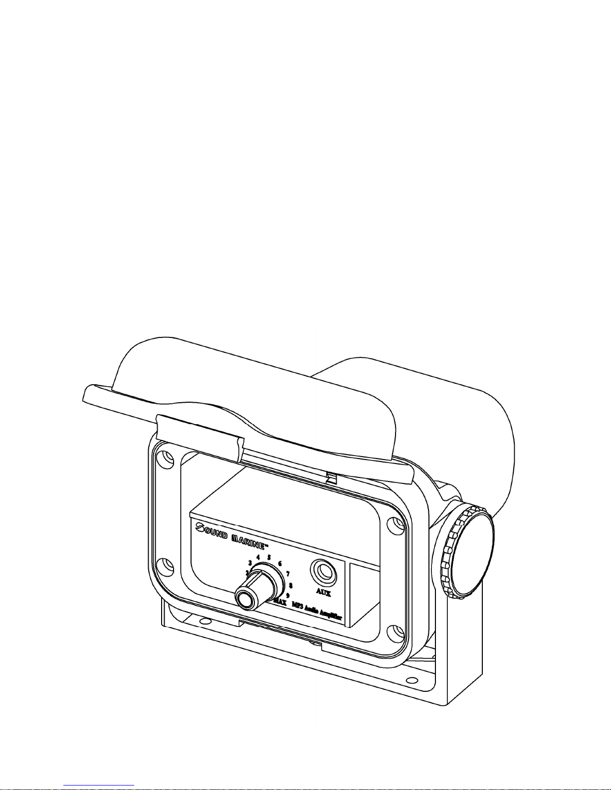
The SM-200 and SM-300 are designed to provide the maximum waterproof protection to your
audio/MP-3 player. The housings are compatible with most of the audio devices with a 3.5mm plug
and they are intended for use in a marine environment. There is a built-in microphone which would
allow you to have a voice conversation while still the front cover is down. The housings are designed
to be waterproof with IP 65 rating. However, direct submersion of the housing under water may
induce damage to the unit and your audio/MP-3 player.
Keep the front cover down to provide the maximum protection. After any user operation, close the
front cover and ensure the seal is complete. The unit will provide protection against splashes of
water, dust, sand and other substances.
Contents
Introduction ………………………………………………………………………………….………………………………….1
Applications ……………………………………………………………………………………….……………………………1
Safety precaution …………………………………………………………………………………………….………………..1
Specification ………………………………………………………………………………………….………………………...2
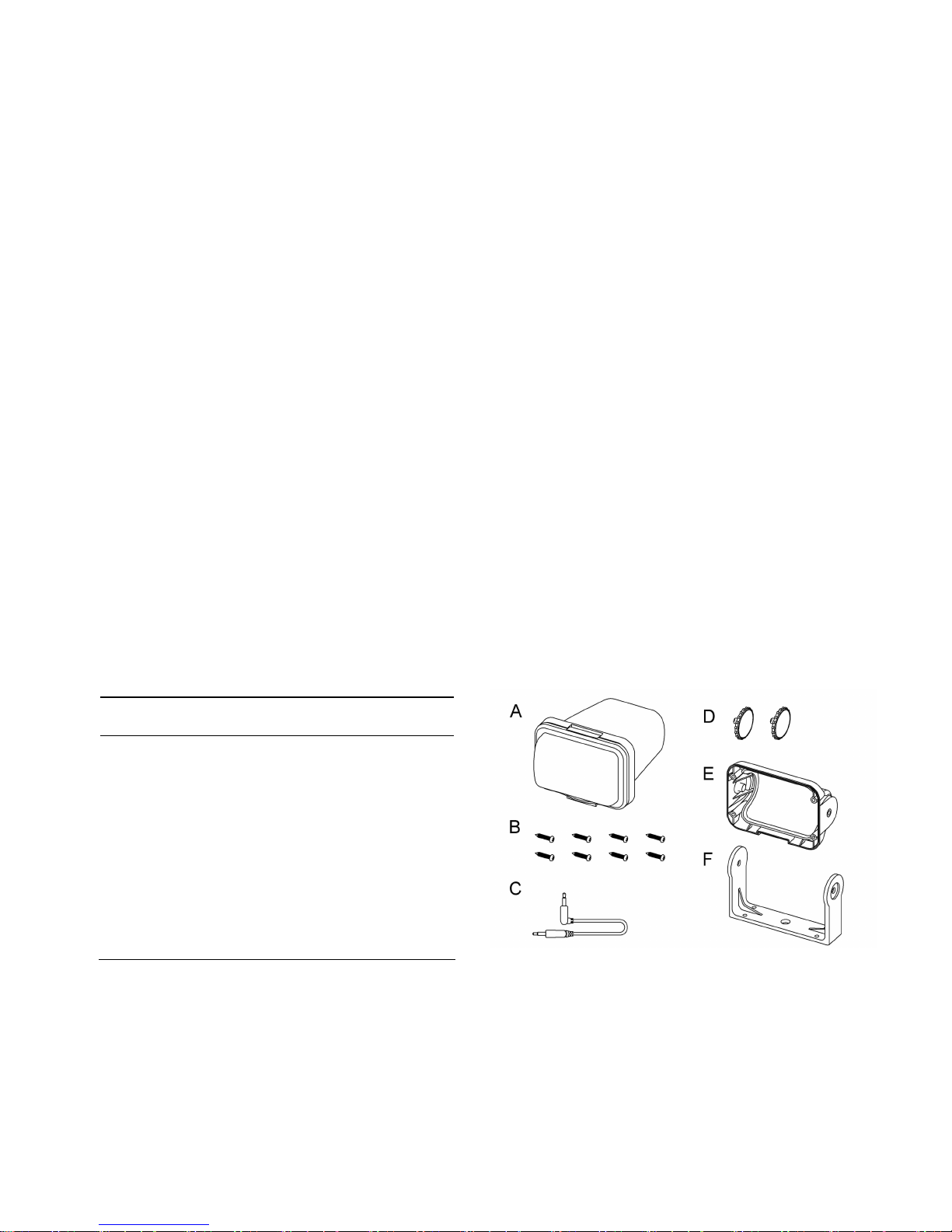
Parts list …………………………………………………………………………………………………………….…………..2
Select the best location for mounting …………………………………………………………………………….………….3
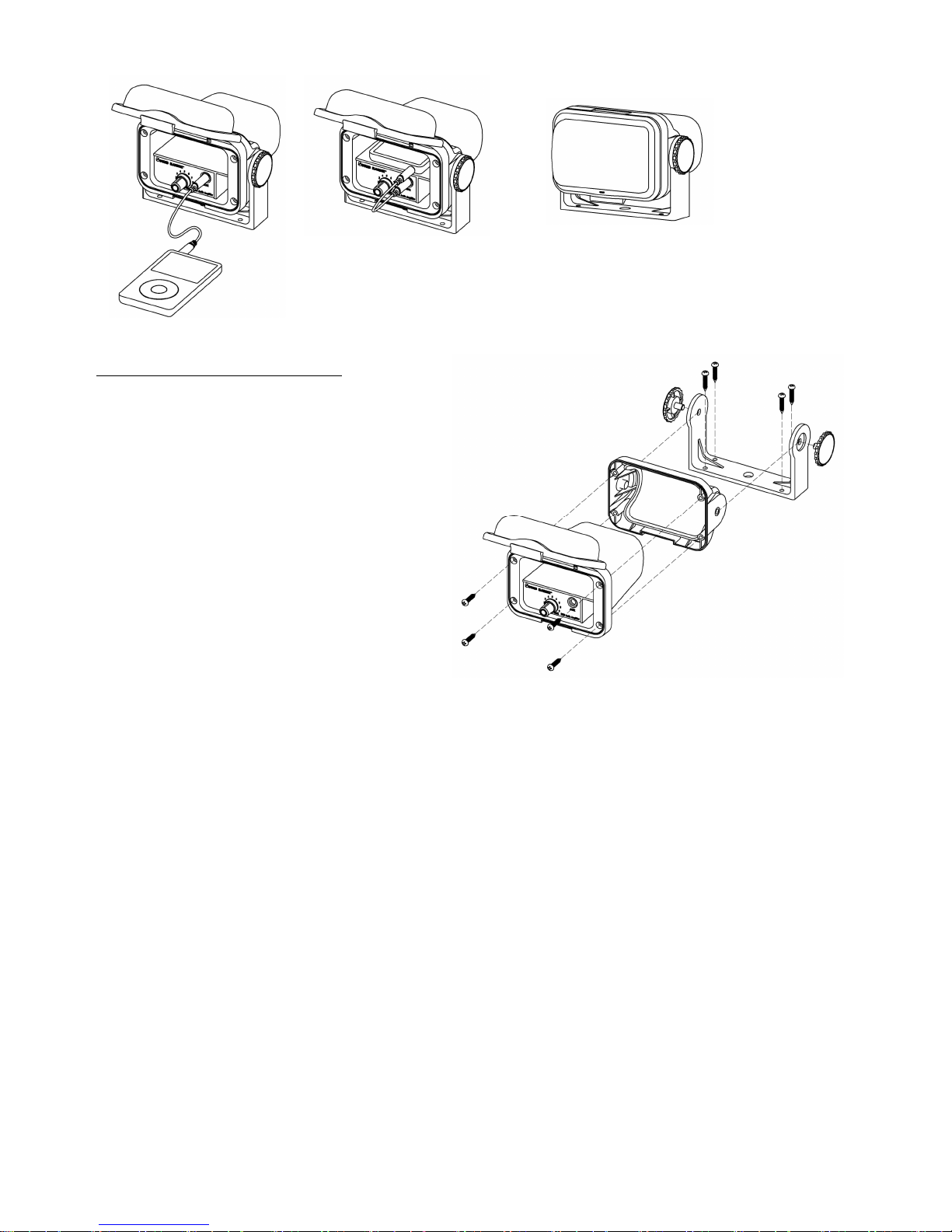
Amplifier installation manual ……………………………………..……….……………………………………………..……3
Loudspeaker installation manual ……………………………………..………………..………………………………….…6
2. Applications
SM-200 and SM-300 are built to withstand tough challenges in different outdoor / marine
environments. They can be installed at locations with high humidity and high chance of water
splashes (SPA room, sauna, swimming pool, etc). Vehicles suitable for SM-200/SM-300 installation
include:
Motorbike
Personal watercraft (PWC)
All terrain vehicle (ATV)
Snowmobile
Utility task vehicle (UTV)
Golf car
Recreational vehicle (RV)
Watercraft / boat
3. Safety Precaution
Read the manual before installation. It contains important information for all users.
Turn off the electricity supply before beginning the installation
For electric drill, ensure it is connected to the ground properly and the area is free of any liquid.
If any problem occurs during the installation, please contact your local dealer for advice before
proceeding. Contract professionals if necessary.
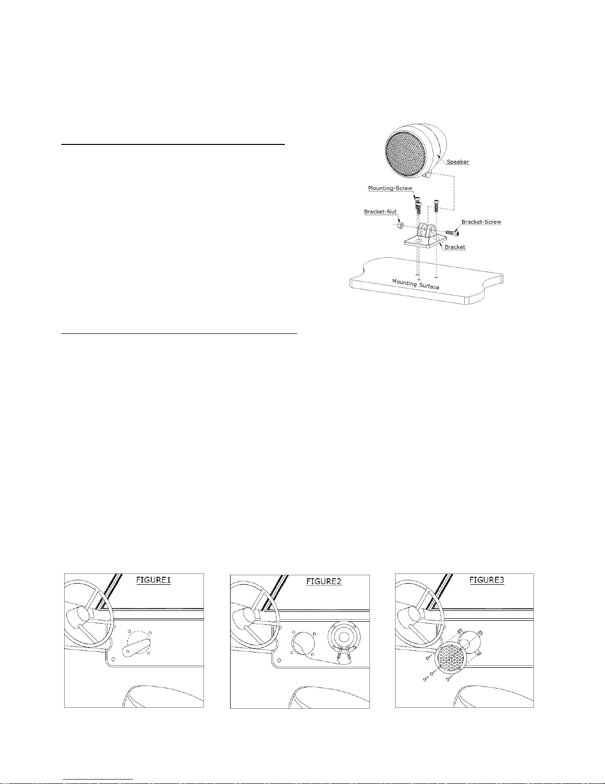
Jet-engine speaker installation manual
1) Mount the plastic bracket on the chosen flat
surface with the screws provided in the package
2) Hold the jet-engine speaker in position and
secure the mounting with a screw and a nut
3) Adjust the projecting angle of the speaker and
tighten the screw
If you are in doubt with the stability of the mounting
surface, please consult your local dealer.
Flush-mount speaker installation manual
8. Loudspeaker Installation Manual
Read the following installation manual carefully before proceeding. If you are unfamiliar with wiring
electronic devices, consult your local dealer or contract professionals. False wiring could damage the
amplifier and the rest of audio system.
1) Select a mounting location which will allow the speaker to lay flat and has adequate space.
2) Use the supplied template to mark the mounting holes. See Figure1.
3) Drill a starter hole in the center of the mounting hole and use a hacksaw blade or a similar tool, cut
the mount hole.
4) Drill the four 1/8" mounting holes.
5) Connect the speaker wire to the speaker terminals and route to stereo. Be sure stripe wire is
connected to the positive (+) terminal of speaker. See Figure2.
6) Slide the four U-Clips over the mounting holes and press to hold in place. See Figure3.
7) Place a bead of RTV sealant (or equivalent) around the back rim of speaker basket.
8) Secure the unit with provided screws for integrated speakers. Or for flush-mount speakers,
tighten the screws to secure the unit first before fitting the cover grille onto the speaker.
If you are in doubt with the stability of the mounting surface, please consult your local dealer.