Greyhound 65162 User guide

9 HP RIDE-ON TRENCHER
Model
65162
SET UP, OPERATING, AND SERVICING
INSTRUCTIONS
WARNING!
IMPORTANT INFORMATION
The Hitch Coupler MUST be properly
secured to the hitch ball of the towing vehicle.
After assembly and attachment, pull up and
down on the Hitch Coupler to make sure the
hitch ball is tting snugly in the Hitch Coupler.
There must be no play between the hitch
ball and Hitch Coupler. If there is play, tighten
the Adjustment Nut until no play is present. If
the Adjustment Nut is too tight, the Handle
will not lock. Carefully read and follow
the complete instructions in this manual
BEFORE setup or use.
If the Coupler is not secured
properly, the ball could come loose
while the Log Splitter is in motion,
possibly causing property damage,
SERIOUS PERSONAL INJURY, or
DEATH.
Visit our website at: http://www.harborfreight.com
Read this material before using this product.
Failure to do so can result in serious injury.
SAVE THIS MANUAL.
Copyright©2008 by Harbor Freight Tools®. All rights reserved. No portion of this
manual or any artwork contained herein may be reproduced in any shape or form
without the express written consent of Harbor Freight Tools. Diagrams within this
manual may not be drawn proportionally. Due to continuing improvements, actual
product may differ slightly from the product described herein. Tools required for
assembly and service may not be included.
For technical questions or replacement parts, please call 1-800-444-3353.
Revised 11a

Page 2SKU 65162 For technical questions, please call 1-800-444-3353.
CONTENTS
IMPORTANT SAFETY
INFORMATION ............................ 4
SET UP PRECAUTIONS .................... 4
OPERATING PRECAUTIONS............5
SERVICE PRECAUTIONS............. 6
REFUELING:.................................7
TRENCHER PRECAUTIONS ........ 7
BASIC SPECIFICATIONS ............. 8
UNPACKING .................................. 8
SET UP INSTRUCTIONS............... 8
ASSEMBLY.........................................8
ATTACHING THE LEG ASSEMBLY 10
PURGING THE CYLINDER..............12
OPERATING INSTRUCTIONS .... 12
STARTING THE ENGINE .................12
CHECKING ENGINE OIL LEVEL12
ENGINE DIAGRAM...................... 13
CHECKING FUEL LEVEL........... 14
BREAK-IN PERIOD ....................14
EQUIPMENT OPERATION...............15
MOVING THE TRENCHER.........16
TRANSPORTING THE
TRENCHER ..............................17
TECHNICAL SPECIFICATIONS.. 19
SERVICING.................................. 19
MAINTENANCE PROCEDURES .....19
ENGINE OIL CHANGE ............... 19
AIR FILTER ELEMENT
MAINTENANCE .......................19
SPARK PLUG MAINTENANCE..20
FUEL FILTER REPLACEMENT
(IF EQUIPPED).........................20
CLEANING, MAINTENANCE, AND
LUBRICATION SCHEDULE .......... 21
AFTER 20 OPERATION HOUR
BREAK-IN PERIOD: ................21
AFTER EVERY 25 OPERATION
HOURS:....................................21
AFTER EVERY 50 OPERATION
HOURS:....................................21
AFTER EVERY 100
OPERATION HOURS:..............21
AFTER EVERY 300
OPERATION HOURS:..............21
PERIODICALLY: .........................21
STORAGE ........................................21
LUBRICATION POINTS ...................22
TROUBLESHOOTING......................23
PARTS LIST................................. 25
GENERAL ASSEMBLY
DIAGRAM .................................. 26
CYLINDER HEAD PARTS LIST
& DIAGRAM .............................. 27
CRANK CASE PARTS LIST &
DIAGRAM .................................. 28
CRANK CASE COVER PARTS
LIST AND DIAGRAM................. 29
CRANKSHAFT/PISTON PARTS
LIST & DIAGRAM...................... 30
GAS DISTRIBUTION
ADJUSTMENT SYSTEM
PARTS LIST & DIAGRAM......... 31
STARTER SUBASSEMBLY
PARTS LIST & DIAGRAM......... 32
DIVERSION ASSEMBLY PARTS
LIST & DIAGRAM...................... 33

Page 3SKU 65162 For technical questions, please call 1-800-444-3353.
CARBURETOR PARTS LIST &
DIAGRAM .................................. 34
FLYWHEEL/COIL ASSEMBLY
PARTS LIST & DIAGRAM......... 35
CONTROL SYSTEM PARTS
LIST & DIAGRAM...................... 36
AIR CLEANER PARTS LIST &
DIAGRAM .................................. 37
MUFFLER PARTS LIST &
DIAGRAM .................................. 38
FUEL TANK PARTS LIST &
DIAGRAM .................................. 39
LIMITED 1 YEAR / 90 DAY
WARRANTY .............................. 40
EMISSION CONTROL SYSTEM
WARRANTY .............................. 40

Page 4SKU 65162 For technical questions, please call 1-800-444-3353.
SAVE THIS MANUAL
Keep this manual for the safety
warnings and precautions, assembly,
operating, inspection, maintenance and
cleaning procedures. Write the product’s
serial number in the back of the manual near
the assembly diagram (or month and year of
purchase if product has no number). Keep
this manual and the receipt in a safe and dry
place for future reference.
IMPORTANT SAFETY
INFORMATION
In this manual, on the labeling,
and all other information
provided with this product:
This is the safety alert
symbol. It is used to alert
you to potential personal
injury hazards. Obey all
safety messages that
follow this symbol to avoid
possible injury or death.
DANGER indicates
a hazardous
situation which, if not
avoided, will result in death or
serious injury.
WARNING
indicates a
hazardous situation which, if
not avoided, could result in
death or serious injury.
CAUTION, used
with the safety
alert symbol, indicates a
hazardous situation which, if
not avoided, could result in
minor or moderate injury.
NOTICE is used to
address practices
not related to personal injury.
CAUTION, without
the safety alert
symbol, is used to address
practices not related to
personal injury.
WARNING! Read all instructions.
Failure to follow all instructions
listed below may result in re,
serious injury and/or DEATH.
The warnings and precautions
discussed in this manual cannot
cover all possible conditions and
situations that may occur. It must
be understood by the operator that
common sense and caution are
factors which cannot be built into
this product, but must be supplied
by the operator.
SAVE THESE INSTRUCTIONS
SET UP PRECAUTIONS
Gasoline fuel and fumes are1.
ammable, and potentially explosive.
Use proper fuel storage and handling
procedures. Do not store fuel or
other ammable materials nearby.
Have multiple ABC class re 2.
extinguishers nearby.
This equipment has a spark3.
arresting mufer included. A spark
arresting mufer is required by law
in California, on some US Forest
Service land, and possibly in other
areas or situations.
Set up and use only on a at, level, 4.
well-ventilated surface.
DANGER
WARNING
CAUTION
Notice
CAUTION

Page 5SKU 65162 For technical questions, please call 1-800-444-3353.
Wear ANSI-approved safety goggles,5.
heavy-duty work gloves, and dust
mask/respirator during set up and
use.
Use only oil and fuel recommended6.
in the “Specications” section of this
manual.
OPERATING PRECAUTIONS
1. CARBON MONOXIDE
HAZARD
Using an engine indoors
CAN KILL YOU IN
MINUTES.
Engine exhaust contains carbon
monoxide. This is a poison you
cannot see or smell.
NEVER use inside a home or garage,
EVEN IF doors and windows are
open.
Only use OUTSIDE and far away
from windows, doors, and vents.
Keep children and observers 20 feet2.
away from the equipment while it is
operating.
Do not leave the equipment3.
unattended when it is running. Turn
off the equipment (and remove safety
keys, if available) before leaving the
work area.
Wear ANSI-approved safety goggles4.
and hearing protection during use.
People with pacemakers should5.
consult their physician(s) before
use. Electromagnetic elds in close
proximity to a heart pacemaker could
cause pacemaker interference
or pacemaker failure. Caution is
necessary when near the engine’s
magneto or recoil starter.
Use only accessories that are6.
recommended by Harbor Freight
Tools for your model. Accessories
that may be suitable for one piece of
equipment may become hazardous
when used on another piece of
equipment.
Stay alert, watch what you are7.
doing and use common sense when
operating a piece of equipment. Do
not use a piece of equipment while
tired or under the inuence of drugs,
alcohol or medication.
Do not overreach. Keep proper8.
balance at all times. This enables
better control of the equipment in
unexpected situations.
Dress properly. Do not wear loose9.
clothing or jewelry. Keep hair,
clothing and gloves away from
moving parts. Loose clothes, jewelry
or long hair can be caught in moving
parts.
Parts of the equipment, especially10.
exhaust system components, get
very hot during use. Stay clear of hot
parts.
Do not cover the engine or equipment11.
during operation.
Keep the equipment, engine, and12.
surrounding area clean at all times.
Use the equipment, accessories, etc.,13.
in accordance with these instructions
and in the manner intended for the
particular type of equipment, taking
into account the working conditions
and the work to be performed. Use
of the equipment for operations
different from those intended could
result in a hazardous situation.
Do not operate the equipment with14.
known leaks in the engine’s fuel system.

Page 6SKU 65162 For technical questions, please call 1-800-444-3353.
This product contains or, when15.
used, produces a chemical known
to the State of California to cause
cancer and birth defects or other
reproductive harm. (California Health
& Safety Code § 25249.5, et seq.)
When spills of fuel or oil occur, they16.
must be cleaned up immediately.
Dispose of uids and cleaning
materials as per any local, state,
or federal codes and regulations.
Store oil rags in a bottom-ventilated,
covered, metal container.
Keep hands and feet away from17.
moving parts. Do not reach over or
across equipment while operating.
Before use, check for misalignment18.
or binding of moving parts, breakage
of parts, and any other condition
that may affect the equipment’s
operation. If damaged, have the
equipment serviced before use.
Many accidents are caused by poorly
maintained equipment.
Use the correct equipment for the19.
application. Do not modify the
equipment and do not use the
equipment for a purpose for which it
is not intended.
SERVICE PRECAUTIONS
Before service, maintenance, or1.
cleaning:
Turn the engine switch to itsa.
“OFF” position.
Allow the engine to completely cool.b.
Then, remove the spark plugc.
wire(s) from the spark plug(s).
Keep all safety guards in place and2.
in proper working order. Safety
guards include mufer, air cleaner,
mechanical guards, and heat shields,
among other guards.
Do not alter or adjust any part of3.
the equipment or its engine that
is sealed by the manufacturer
or distributor. Only a qualied
service technician may adjust
parts that may increase or
decrease governed engine speed.
Wear ANSI-approved safety goggles,4.
heavy-duty work gloves, steel toe
work boots, dust mask/respirator and
hard hat during use and service.
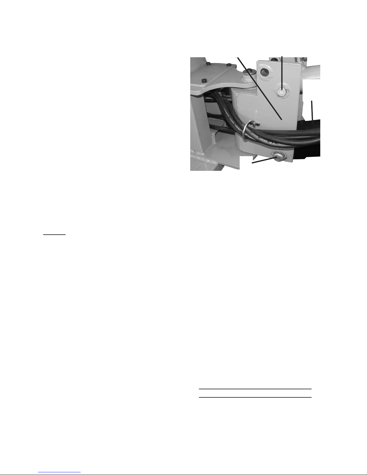
Do not allow the hydraulic hose to5.
come in contact with any hot part
of the unit. The hose might be
damaged, possibly causing it to burst
or leak under high pressure.
Maintain labels and nameplates6.
on the equipment. These carry
important information. If unreadable
or missing, contact Harbor Freight
Tools for a replacement.
Have the equipment serviced by a7.
qualied repair person using only
identical replacement parts. This
will ensure that the safety of the
equipment is maintained. Do not
attempt any service or maintenance
procedures not explained in this
manual or any procedures that you
are uncertain about your ability to
perform safely or correctly.
Store equipment out of the reach of8.
children.
Follow scheduled engine and9.
equipment maintenance.

Page 7SKU 65162 For technical questions, please call 1-800-444-3353.
Refueling:
Do not smoke, or allow sparks,1.
ames, or other sources of ignition
around the equipment, especially
when refuelling.
Do not rell the fuel tank while the 2.
engine is running or hot.
Do not ll fuel tank to the top. Leave 3.
a little room for the fuel to expand as
needed.
Refuel in a well-ventilated area only.4.
TRENCHER PRECAUTIONS
Always make sure the hitch coupler1.
is securely xed to the vehicle before
moving it. If the Coupler is not se-
cured properly, the link could come
loose while the trailer is in motion,
possibly causing property damage,
SERIOUS PERSONAL INJURY, or
DEATH.
Contact local utility companies2.
before beginning any project. Buried
utility lines may not be marked
and, if struck, can cause SERIOUS
PERSONAL INJURY or DEATH.
WARNING: Some dust created by3.
power sanding, sawing, grinding,
drilling, and other construction
activities, contains chemicals
known [to the State of California] to
cause cancer, birth defects or other
reproductive harm. Some examples
of these chemicals are:
• Lead from lead-based paints
• Crystalline silica from bricks and
cement or other masonry products
• Arsenic and chromium from
chemically treated lumber
Your risk from these exposures
varies, depending on how often you
do this type of work. To reduce your
exposure to these chemicals: work in
a well ventilated area, and work with
approved safety equipment, such as
those dust masks that are specially
designed to lter out microscopic
particles. (California Health & Safety
Code § 25249.5, et seq.)
Never place your hands or body near4.
a hydraulic uid leak. High-pressure
uid can be forced under the skin
resulting in serious injury.
Do not exceed 30 MPH when towing5.
the Trencher.
Do not tow the Trencher on roads or6.
highways. This product is not D.O.T.
compliant, and is not road legal.
SAVE THESE
INSTRUCTIONS.

Page 8SKU 65162 For technical questions, please call 1-800-444-3353.
BASIC SPECIFICATIONS
Fuel Type 86+ octane unleaded
gasoline
Capacity 1.58 Gallons
Engine Oil Type SAE 10W 30 above 32° F
5W30 at 32° F or below
Capacity 1.2 Quarts
Hydraulic Oil 3.5 Gallons
Engine Speed 3,600 RPM
Engine Family 6CGP.2702GA
Tire Ination 65 PSI
Digging Depth 5-1/2 and 7 Feet Deep
Maximum Digging
Reach 8 Feet
Spool Valve Rated 10.6 G.P.M.
Pump Rated 2.7 G.P.M.
Boom Travel 60° Left/Right
Bucket Load Capacity 1.24 Cubic Feet
Hitch Ball size 1-7/8” Diameter
Note: Additional specications found
in the TECHNICAL ENGINE
SPECIFICATIONS chart in this
manual.
The emission control system for this
product’s Engine is warranted for standards
set by the U.S. Environmental Protection
Agency and by the California Air Resources
Board (also known as CARB). For warranty
information, refer to the last pages of this
manual.
At high altitudes, the engine’s carburetor,
governor (if so equipped), and any other
parts that control the fuel-air ratio will need to
be adjusted by a qualied mechanic to allow
efcient high-altitude use and to prevent
damage to the engine and any other devices
used with this product.
UNPACKING
When unpacking, check to make sure
that the item is intact and undamaged. If
any parts are missing or broken, please call
Harbor Freight Tools at the number shown
on the cover of this manual as soon as
possible.
SET UP INSTRUCTIONS
Read the ENTIRE IMPORTANT
SAFETY INFORMATION
section at the beginning of this
manual including all text under
subheadings therein before set
up or use of this product.
Risk of accidental
starting; resulting
in serious personal injury.
Turn the Power Switch of the
equipment to its “OFF”
position, wait for the engine to
cool, and unplug the spark
plug wire(s) before
assembling or making any
adjustments to the equipment.
Note: For additional information regarding
the parts listed in the following pages,
refer to the Assembly Diagram near
the end of this manual.
Assembly
This equipment has a spark arresting1.
mufer. A spark arresting mufer is
required by law in California, on some
US Forest Service land, and possibly
in other areas or situations.
Due to the size of the Trencher and2.
its components, assistance may be
required during the entire assembly
process.
Use jacks (not included) to evenly3.
raise the Frame Assembly (90)
& support with jack stands (not
included).
WARNING
REV 09b, 09i

Page 9SKU 65162 For technical questions, please call 1-800-444-3353.

Page 10SKU 65162 For technical questions, please call 1-800-444-3353.
Mount both Axles (50) near the boom4.
end of the frame and secure with
Lock Pins (82).
Place a Tire (52) over the four studs5.
on each Hub. Secure the Tires to
the Hubs, using four Lug Nuts (53)
per Tire. The lug nuts must be snug.
Inate the tires to 65 PSI.
Slightly raise the Jacks, remove the6.
Jack Stands, then lower the Jacks.
Block the tires and tighten the Lug
Nuts to at least 90 Ft-Lbs.
Attach Seat (73) to the Seat Bottom7.
Plate (10) and secure both Seat and
Plate to the post on top of Hydraulic
Oil Tank.
Attach the Control Support (3) to the8.
Frame Assembly (90) using four Hex
Bolts (81).
NOTE: The Hydraulics of this unit are
tested before shipment. There
may be hydraulic uid present in
components. Assemble the unit in
an area that will not be damaged
by leaking hydraulic uid. It is
recommended that you wrap
rags securely over the Hydraulic
connectors on all the Cylinders during
assembly. Wear splash-resistant
ANSI approved safety goggles and
other protective gear to prevent injury
from leaking uid.
Attach the Main Boom (36) to the9.
Boom Pivot (38) using the Pin (42)
through the bottom hole and Clevis
Pin No. 1 (29) through the upper
hole. Secure both pins with Hair Pin
Clip (31); Pin (42) requires one Cotter
pin on each end. See photo above
right.
Boom
Pivot (38)
Clevis Pin
No. 1 (29)
Main
Boom
(36)
Pin
(42)
Mount the Boom Extension (34) to10.
the Main Boom (36) using the Pin
(42), left, and Clevis Pin No. 1 (29),
top. Secure both pins with Hair Pin
Clip (31).
Attach the Hitch Coupler (58) to11.
the Frame Assembly (90) under the
Engine (74) using Hex Bolts (75) and
Hex HD. Bolt (72).
Connect, tighten, and check all12.
hydraulic hose ttings to the proper
connections, as shown in the Hose
Connection Diagram. Hoses and
ttings are numbered. Tighten all
ttings.
Open the Hydraulic Fluid Fill Plug13.
(11). Top off the Hydraulic Fluid
Reservoir with high quality hydraulic
uid. Check that the Fluid level is
between the lines on the attached
Dipstick. Close the Hydraulic Fluid Fill
Plug securely.
Attaching the Leg Assembly
To use the Trencher, the Leg1.
Assemblies must be installed next to
the Boom (36), and the Wheels and
Axles (50) moved to the rear. REV 09i

Page 11SKU 65162 For technical questions, please call 1-800-444-3353.
REV 09b, 11a
Hose Connection Diagram
Boom Extension (34)
Pin
(42)
Clevis Pin No. 1
(29)
Seat (73)
Hydraulic
Fluid
Reservoir
Hydraulic Fluid
Fill Plug (11)
TOW CONFIGURATION
Engine (74)
Frame Assy. (90)
Mount Hitch
Coupler (58)
Here
Control
Panel
(9)
Bucket
Control
Cylinder
Boom
Extension
Cylinder
Main Boom
Cylinder
Boom Swing
Cylinder
Control Panel / Spool Valve (9)
Hydraulic Fluid
Reservoir
part of Frame (90)
Hydraulic
Pump (65)
2
8
10
4
9
3
5
7

Page 12SKU 65162 For technical questions, please call 1-800-444-3353.
Move the Trencher to the work area2.
(See “Starting The Engine” - page
14).
Start the engine and use the Boom3.
Controls to curl the bucket toward the
boom without touching the ground.
Moving the Bucket Assembly (32)
down to the ground will raise the
Frame Assembly (90). Lift the Tires
just off the ground and stop.
Ensure the controls will not be4.
touched or bumped, and that the
Trencher will remain motionless.
Never place any part of your body
under the trencher.
With the Tires (52) off the ground,5.
remove the Wheel and Axle (50)
to the operator’s left and replace
with the left side Extension Leg (19)
and Leg Assembly (24). Direct the
Extension Leg so it turns toward the
Bucket end of the Trencher. Secure
with Lock Pin No. 2 (82). Repeat
procedure for the right side. Raise
Bucket Assembly again to lower onto
Leg Assembly, and turn Engine off.
Using a jack and jack stands (not6.
included), raise up the engine end of
the trencher and disconnect from the
towing hitch. Slide the Wheels and
Axles (50) into the engine end of the
Frame (90). Secure each axle with
Lock Pin No. 2 (82).
Purging the Cylinder
Remove all Safety Locking Pins (15),1.
disengage the Safety Latch (41) and
loosen Hydraulic Tank Fill Plug (11).
Press forward on the Boom Swing2.
Lever (located on Control Panel (9)
until the Boom stops moving, then
pull back on it until it moves in the
other direction. Center the Boom.
Press forward on the Main Boom3.
Lever until the Main Boom is fully
raised. Then, press Forward on the
Boom Extension Lever until the Boom
is fully extended.
Press forward on the Bucket Lever4.
until the bucket is fully extended. Pull
back on the lever to retract it fully.
Pull back on the Boom Extension5.
Lever until the Boom is pulled back
all the way. Pull back on the Main
Boom Lever until the Main Boom is
lowered completely.
Adjust the boom back to its rest6.
position and replace all locking
devices.
Shut off the Engine, check the7.
Hydraulic Fluid level and rell as
necessary.
Note: The Fill Plug is vented. When8.
tightening the Fill Plug, tighten it
securely then back it off slightly.
OPERATING INSTRUCTIONS
Read the ENTIRE IMPORTANT
SAFETY INFORMATION
section at the beginning of this
manual including all text under
subheadings therein before set
up or use of this product.
Starting the Engine
Inspect engine and equipment
looking for damaged, loose,
and missing parts before
set up and starting. If any
REV 09i

Page 13SKU 65162 For technical questions, please call 1-800-444-3353.
ENGINE DIAGRAM
COMPONENTS & CONTROL LOCATIONS
3
2.
COMPONENTS & CONTROL LOCATIONS
THROTTLE LEVER
MUFFLER
SPARK PLUG
AIR CLEANER
FUEL VALVE LEVER
CHOKE LEVER
RECOIL STARTER
STARTER GRIP
IGNITION SWITCH
FUEL FILLER CAP
FUEL TANK
OIL DRAIN PLUG
OIL FILLER CAP/DIPSTICK

Page 14SKU 65162 For technical questions, please call 1-800-444-3353.
problems are found, do not use
equipment until xed properly.
Checking Engine Oil Level
CAUTION! Your Warranty is VOID if the
engine’s crankcase is not properly
lled with oil before each use. Before
each use, check the oil level. Do not
run the engine with low or no engine
oil. Running the engine with no or
low engine oil WILL permanently
damage the engine.
Clean the Oil Filler Cap and the area1.
around it.
Remove the Oil Filler Cap/Dipstick.2.
Read the engine service manual for
the proper way to check the oil level.
If the oil level is low, add the proper3.
type and weight. See information
below.
Oil type:
32° F or above = SAE 10W-30
Below 32° F = SAE 5W-30.
Replace the Oil Filler Cap.4.
CAUTION! Do not run the engine with too
little or too much oil. The engine will
be permanently damaged.
Checking Fuel Level
WARNING! To prevent re,
shut the engine off and wait
for it to cool before adding
fuel. Do not smoke.
Clean the Fuel Filler Cap and the1.
area around it.
To Check the fuel level, unscrew and1.
remove the Fuel Filler Cap.
Mix fuel stabilizer (not included)2.
with 86 octane (or better) unleaded
gasoline according to fuel stabilizer
directions.
Fill the Fuel Tank to about 1 inch3.
under the lip of the gasoline tank
with the stabilized unleaded gasoline
mixture.
Then replace the Fuel Filler Cap.4.
Start Procedure
Before starting the engine:
Follow the Set Upa.
Instructions to prepare the
equipment.
Inspect the equipment andb.
engine.
Fill the engine with thec.
proper amount and type of
both fuel and oil.
Read the Equipmentd.
Operation section that
follows.
Turn the fuel valve lever to its1.
“OPEN” position.
Turn the ignition switch to its ON or2.
RUN position.
Then, turn the engine choke lever to3.
its “CHOKE” position. Set the choke
lever in the “RUN” position when
starting a warm engine.
Grasp the starter handle, and pull4.
slowly until resistance is felt. While
holding the handle, allow the starter
rope to rewind slowly. Then, pull the
starter handle with a rapid, full arm
stroke. Once again while holding
the handle, allow the rope to rewind
slowly. Repeat as necessary, until
the engine starts.

Page 15SKU 65162 For technical questions, please call 1-800-444-3353.
After the engine starts and warms5.
up, slowly move the choke lever to its
“RUN” position.
IMPORTANT: Allow the engine to6.
run at no load for ve minutes with no
load after each start-up so that the
engine can stabilize.
Break-in Period
Breaking-in the engine will help to1.
ensure proper equipment and engine
operation.
The operational break-in period will2.
last about 3 hours of use. During this
period:
Do not apply a heavy load to the•
equipment.
Do not operate the engine at its•
maximum speed.
The maintenance break-in period will3.
last about 20 hours of use. After this
period:
Change the engine oil.•
Under normal operating conditions
subsequent maintenance follows
the schedule explained in the
MAINTENANCE AND SERVICING
section.
Equipment Operation
This Trencher can be used with two1.
arm positions. See illustrations to the
right.
Cylinder (26) Pin
Main
Boom
(36)
Boom
Pivot
(38)
Cylinder (26) Pin
Boom
Pivot
(38)
Main
Boom
(36)
REV 09f

Page 16SKU 65162 For technical questions, please call 1-800-444-3353.
While the end of the boom is being2.
supported; remove the Pin (29), align
the cylinder with the appropriate hole,
insert the Pin (29), and secure it with
the Hair Pin Clip (31).
With the Engine running, sit in the3.
Operator Seat (73) and pull the Boom
Lever control backward to raise the
Main Boom (36).
Pull back on the Boom Extension4.
handle control to raise the Boom
Extension (34).
Push forward on the Bucket handle5.
control to open the Bucket Assembly.
(32).
Push forward on the Boom handle6.
to lower the Boom until the Bucket
reaches the ground.
Pull back on the Bucket Lever control7.
until the Bucket scoops up the dirt.
Pull back on both the Boom and8.
Boom Extension control levers to
raise the load.
Press in, or push out, the Boom9.
Swing control levers to move the
Bucket left or right. Note: The Boom’s
travel is 60 degrees left and 60
degrees right.
Press in on the Bucket control handle10.
to dump the load.
Moving the Trencher
One method for moving the trencher11.
around the work area is by using the
Boom to push the Trencher across
the ground.
12. WARNING: This technique
can be difcult to control and
should only be attempted by an
experienced operator. The stability
of the Trencher is dependent on the
stability of the ground; if you choose
to move the Trencher in this way, do
so at your own risk. Do not use the
Trencher near ditches or drop-offs.
Swing the Bucket inward so that the13.
front of the bucket, not the scoop, is
facing downward. Press the Bucket
down onto a solid piece of ground
and press down hard enough to raise
the front legs off the ground.
Carefully operate the controls to14.
move the boom and slowly roll
yourself in the desired direction. Be
certain that the Tires and the new
resting places for the Legs all remain
on solid, stable ground.
Controls operate by
pushing in or pulling out Bucket: IN - OUT
Boom Extension: IN - OUT
Boom: IN - OUT
Boom Swing: LEFT - RIGHT
REV 09i

Page 17SKU 65162 For technical questions, please call 1-800-444-3353.
After you have repositioned the15.
Trencher, raise the Boom to lower the
outriggers back onto the ground. The
procedure can be repeated to move
farther.
Transporting the Trencher
Lock the Boom in Place. Use the16.
Bucket Lever to line the hole on the
Bucket (32) up with the hole on the
Boom Extension (34). Insert a Safety
Locking Pin (15) and secure with a
Ball Pin.
Use the Boom Swing Lever to line up17.
the hole in the Boom Pivot (38) with
the Hole in the Frame (90). Insert a
Safety Locking Pin (15) and secure
with a Ball Pin.
Safety
Latch (41)
Safety Locking
Pin (15)
Put the Boom into the Shallow18.
Position and raise it until the pin on
the side of the Main Boom (36) is
close enough for the Safety Latch
(41) to swing over it. To use the
Safety Latch, pull out on the handle,
swing it over the pin, and lower it over
the pin, locking it in place.
When transporting the Trencher,19.
make sure your hitch (not included)
is compatible with the Hitch Coupler
(92). Follow all of the safety warnings
for towing in your vehicle’s manual.
The Hitch Coupler will only accept a 2
inch hitch ball.
To reduce friction between the hitch20.
ball and Hitch Coupler (58), apply a
layer of heavy weight grease over the
hitch ball.
See illustration below. Temporarily21.
remove the “R” Pin and Safety Pin.
Then, pull up on the Trigger and lift
up on the Handle.
Safety Pin
R-Pin
Hitch
Coupler (58)
Place the Hitch Coupler (58) over22.
the vehicle’s hitch ball, pull the
trigger, push down on the Handle,
and release the Trigger, making
sure it locks in the slot. Pull up and
down on the Coupler to make sure
the hitch ball is tting snugly in the
Coupler. There should be no play
between the hitch ball and Coupler. If
there is play, tighten the Adjustment
Nut until no play is present. If the
Adjustment Nut is too tight, the
Handle will not lock. WARNING! If
the Hitch Coupler is not secured
properly, the ball could come loose
while the Trencher is in motion,

Page 18SKU 65162 For technical questions, please call 1-800-444-3353.
possibly causing property damage or
SERIOUS PERSONAL INJURY.
Hitch Ball
(Not Included)
Handle
Trigger
Adjustment
Nut
Safety
Chain
(56)
Make sure to attach each side of23.
the Safety Chain (56) equally to
the towing vehicle’s rear bumper or
frame.
CAUTION! Care must be taken24.
when backing up the Trencher. Only
back up the Trencher on a straight
path. If the Trencher is allowed
to turn off the straight path while
backing up, the Trencher could
jackknife, causing severe damage
to the Trencher and to the towing
vehicle.
To prevent accidents, turn off the25.
engine, wait for it to cool, and
disconnect its spark plug wire after
use. Clean external parts with clean
cloth, then store the equipment out of
children’s reach.

Page 19SKU 65162 For technical questions, please call 1-800-444-3353.
TECHNICAL
SPECIFICATIONS
Engine Type
Single Cylinder 4 stroke
OHV, 9HP Air Cooled,
Recoil Start
Battery Required 12V 18Ah
Bore x Stroke 77mm x 58mm
Displacement 270cc
Compression Ratio 8.2:1
Rotation viewed from PTO
(power takeoff - the output shaft) Counterclockwise
Fuel Type 86+ octane unleaded
gasoline
Capacity 1.58 Gallons
Engine Oil Type SAE 10W30 above 32° F
5W30 at 32° F or below
Capacity 1.2 Quarts
Spark Plug Type NGK®, BPR7ES
LD®, F7TC
Gap 0.028 - 0.031”
Valve
Clearance
Intake 0.15 ± 0.02 mm
Exhaust 0.20 ± 0.02 mm
Speed Idle 1,400 ± 150 RPM
Maximum 3600 RPM
SERVICING
Risk of serious
personal injury
from accidental starting. Turn
the Power Switch of the
equipment to its “OFF”
position, wait for the engine to
cool, and unplug the spark
plug wire(s) before performing
any inspection, maintenance,
or cleaning procedures.
Damaged equipment can fail,
causing serious personal
injury. Do not use damaged
equipment. If abnormal noise,
vibration, or excess smoking
occurs, have the problem
corrected before further use.
Maintenance Procedures
Many maintenance procedures,
including any not detailed
in this manual, will need to
be performed by a qualied
technician for safety. If you
have any doubts about your
ability to safely service the
equipment or engine, have a
qualied technician service the
equipment instead.
Engine Oil Change
CAUTION! Oil is very hot during
operation and can cause burns. Wait
for engine to cool before changing oil.
Place a drain pan (not included)1.
underneath the crankcase’s drain
plug.
Remove the drain plug and drain the2.
oil out. Recycle used oil.
Replace the drain plug and tighten it.3.
Rell the oil to the proper level 4.
following the instructions under the
Starting the Engine section.
Air Filter Element Maintenance
The air cleaner cover is held in place1.
by a wing nut or clamps. Remove it.
Remove the air lter element.2.
Cleaning:3.
For “paper” lter elements:a.
To prevent injury from dust and
debris, wear ANSI-approved safety
goggles, NIOSH-approved dust
mask/respirator, and heavy-duty
work gloves. In a well-ventilated
area away from bystanders, use
pressurized air to blow dust out of
the air lter. If this does not get the
lter reasonably clean, replace it.
WARNING
REV 09b, 09f

Page 20SKU 65162 For technical questions, please call 1-800-444-3353.
For foam lter elements:b.
Wash the element in warm water
and mild detergent several times.
Rinse. Squeeze out excess water
and allow it to dry completely. Soak
the lter in lightweight oil briey, then
squeeze out the excess oil.
Install the new lter or the cleaned 4.
lter. Secure the Air Cleaner Cover
before use.
Spark Plug Maintenance
Disconnect spark plug wire from1.
end of plug. Clean out debris from
around spark plug.
Using a spark plug wrench, remove2.
the spark plug.
Inspect the spark plug:3.
If the electrode is oily, clean it using a
clean, dry rag.
If the electrode has deposits on it,
polish it using emery paper.
If the white insulator is cracked or
chipped, the spark plug needs to be
replaced.
When installing a new spark4.
plug, adjust the plug’s gap to the
specication on the Technical
specication chart. Do not pry
against the electrode, the spark plug
can be damaged.
Install the spark plug into the engine.5.
Gasket-style: Finger-tighten until the
gasket contacts the cylinder head,
then turn about 1/2-2/3 more.
Non-gasket-style: Finger-tighten until
the plug contacts the head, then turn
about 1/16 more.
Apply dielectric spark plug boot6.
protector (not included) to the end of
the spark plug and reattach the wire
securely.
Fuel Filter Replacement (if equipped)
WARNING! RISK OF FIRE
OR EXPLOSION. Replace the
fuel lter in a well-ventilated
area away from ignition
sources. Do not smoke.
Wait for engine to cool before1.
proceeding.
Wear protective gear including, ANSI-2.
approved safety goggles, NIOSH-
approved dust mask/respirator, and
nitrile gloves.
Wipe Fuel Cap and top of Fuel Tank.3.
Remove Fuel Filter (6R). Reattach4.
Fuel Cap to prevent debris from
entering into Gas Tank.
Remove Buel Strainer. Wash with5.
warm water and light detergent.
Flush and let dry.
Reinstall in the Gas Tank.6.
Cleaning, Maintenance, and
Lubrication Schedule
Note: This maintenance schedule
is intended solely as a general
guide. If performance decreases
or if equipment operates unusually,
check systems immediately. The
maintenance needs of each piece
of equipment will differ depending
on factors such as duty cycle,
temperature, air quality, fuel quality,
and other factors.
Note: These procedures are in addition to
the regular checks and maintenance
explained as part of the regular
Table of contents