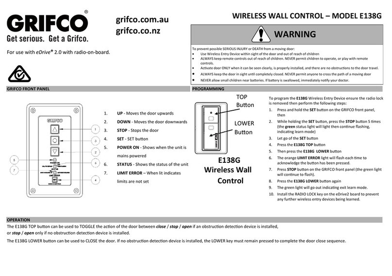
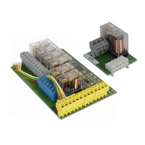
Grifco C10A User manual

grifco.com.au
grifco.co.nz
D-M-ACG/086 191118
Chamberlain New Zealand Ltd
PO Box 100-221
Auckland 0745, New Zealand
Phone toll free 0800 653 667
Chamberlain Australia Pty Ltd
PO Box 1446, Lane Cove
NSW 1595, Australia
Phone toll free 1800 474 326
Electronic Wall
Controller
C10A
Installaon and Users
Manual for C10A ,
C10A Flushmount
and Key Switch Variants:
C21B, C41B
C23B, C43B
C21D-2, C43D-2

2
Safety instrucons 3
Introducon 4
Idenfying your Controller 4-5
Planning 6
Installaon 6
Operaon 7-10
Checking power 7
Door direcon 7
Changing Door Direcon 7
Limit Conrmaon (Jog Direcon) 8
Seng Limits 8
Oponal Third Limit (extended open posion) 9
Seng Limits (Smoke Bae Feature eDrive +2.0) 9
General Operaon 10
Controller Interface 11-12
Auto 11
E-Stop 11
Open 12
Close 12
Stop 12
Edrive +2.0 Advanced Programming 13-14
Schemacs 15-17
C21D C41D 15
C23B C43B 16
C21D-2 C41D-217
Troubleshoong 18
Notes 19
Warranty 20
TABLE OF CONTENTS

3
Safety symbol and signal word review
This commercial door controller has been designed and tested to oer safe service provided it is installed, operated, maintained
and tested in strict accordance with the instrucons and warnings contained in this manual.
WARNING
WARNING
CAUTION
Mechanical
Electrical
When you see this Signal Word on the following pages, it will
alert you to the possibility of damage to your commercial
door and/or the commercial door opener if you do not
comply with the cauonary statements that accompany it.
When you see these Safety Symbols and Signal Words on the
following pages, they will alert you to the possibility of
serious injury or death if you do not comply with the
warnings that accompany them. The hazard may come from
something mechanical or from electric shock.
SAFETY SYMBOL AND SIGNAL WORD REVIEW
WARNING: Important safety instrucons. It is important for the
safety of persons to follow all instrucons. SAVE these instrucons.
THESE ARE IMPORTANT SAFETY INSTRUCTIONS. FOLLOW ALL INSTRUCTIONS AS INCORRECT
INSTALLATION CAN LEAD TO SEVERE INJURY OR DEATH
Keep commercial door balanced. Scking or binding doors must be
repaired. Commercial doors, door springs, pulleys, brackets and
their hardware are under extreme tension and can cause serious
personal injury. Do not aempt to loosen, move or adjust them. Call
for commercial door service.
Disengage all exisng commercial door locks to avoid damage to commercial door.
Install the wall control (or any addional push buons) in a locaon where the
commercial door is visible during operaon . Do not allow children to operate push
buon(s) or remote control(s). Serious personal injury from a closing commercial door
may result from misuse of the opener.
Do not wear rings, watches or loose clothing while installing or
servicing a commercial door opener.
Permanently fasten all supplied labels adjacent to the wall control as a convenient
reference and reminder of safe operang procedures.
To avoid serious personal injury from entanglement, remove all
ropes connected to the commercial door before installing the door
opener.
Acvate opener only when the door is in full view, free of obstrucons and opener is
properly adjusted. No one should enter or leave the building while the door is in
moon.
Installaon and wiring must be in compliance with your local
building and electrical codes. Connect the power supply cord only to
properly earthed mains.
An electrician must disconnect electric power to the commercial door opener before
making repairs or removing covers.
Moisture and water can destroy the electronic components. Make
sure under all circumstances that water moisture or storage
moisture cannot penetrate the electronics. The same applies for
openings and cable entries.
If the supply cord is damaged, it must be replaced by the manufacturer or its service
agent or a similarly qualied person in order to avoid a hazard
A disconnecon device incorporated in the xed wiring must be provided in
accordance with the wiring rules of the country in which it is installed.
Aer the installaon a nal test of the full funcon of the system
and the full funcon of the safety devices must be done.
The actuang member of a biased-o switch is to be located within direct sight of the
door but away from moving parts. Unless it is key operated, it is to be installed at a
minimum height of 1500mm and not accessible to the public.
When operang a biased-o switch, make sure that other persons
are kept away.
Make sure that people who install, maintain or operate the door follow these
instrucons. Keep these instrucons in a safe place so that you can refer to them
quickly when you need to.
The opener cannot be used with a driven part incorporang a
wicket door (unless the opener cannot be operated with the wicket
door open).
If the opener is installed at a height less than 2.5 metres from oor level or any other
level from which the unit can be accessed (eg mezzanine) the installer is responsible
to t guards to the opener to prevent access to the chain drive.
Ensure that entrapment between the driven part and the
surrounding xed parts due to the opening movement of the driven
part is avoided
This appliance is not intended for use by persons (including children) with reduced
physical, sensory or mental capabilies, or lack of experience and knowledge, unless
they have been given supervision or instrucon concerning use of the appliance by a
person responsible for their safety. Children should be supervised to ensure that they
do not play with the appliance.
Motor may become hot during operaon. Appropriate clearance
and/or shielding should be supplied by the installer to ensure any
cabling, wiring and/or other items cannot come in contact with the
motor. If temperature rise exceeds 50⁰C all xed wiring insulaon
must be protected, for example, by insulang sleeving having an
appropriate temperature rang.
Use the commercial door accessory for its intended purpose.

4
Congratulaons on your purchase of a Grifco® Electronic Wall Controller.
This controller is the user interface for the opener. It consists of four buons for control and setup, as well as three indicators to
display the opener status.
INTRODUCTION
IDENTIFYING YOUR CONTROLLER
WARNING
Make sure that people who install, maintain or
operate the door follow these instrucons. It is
advised that the instrucons be kept in a safe place
so that you can refer to them quickly when you
need to.
CAUTION
Please remove any locks ed to the door before
operaon in order to prevent damage to the door.
1) UP - Moves the door upwards
2) DOWN - Moves the door downwards
3) STOP - Stops the door
4) SET - Used to set limits, and other
programmable funcons
5) POWER ON - Shows when the unit is mains powered
(White LED)
6) STATUS - Shows the status of the unit (error codes)
(Green LED)
7) LIMIT ERROR – When lit indicates limits (or stopping
posions) are not set, the door will only
operate in SAFETY inch mode unl limits
are set (or reset).
(Orange LED)

5
IDENTIFYING YOUR CONTROLLER
The key switch modes are detailed below:
C21B/ C41B with basic On-O key isolator
C23B/C43B with “Lock-it-Well” On-O key
isolator
C21D-2/C41D-2 with Mul-Mode key isolator
(O-Auto-Auto/Man)
WARNING
The OFF posion on the key switch DOES NOT ISOLATE POWER. Power must be isolated at the source before accessing the control
enclosure, or working on any aspect of the door or opener.
OFF The C10A controller will not operate
from any source.
WARNING!! THIS IS NOT POWER
ISOLATION!!
ON Enables the use of the C10A front
panel buons, rear panel connecons
and all other inputs via EB1, radio or
toggle input
OFF The C10A controller will not operate
from any source.
WARNING!! THIS IS NOT POWER
ISOLATION!!
AUTO Isolates the C10A front panel UP and
DOWN buons to prevent tampering
(typical mode for car park
environments)
All other inputs remain acve
(EB1, radio or Toggle)
STP and the STOP buon are sll
acve.
OPN and CLS inputs connected to the
rear of the C10A are acve.
AUTO
/ MAN
Enables the use of the C10A front
panel buons, rear panel connecons
and all other inputs via EB1, radio or
toggle input

6
PLANNING
The C10A Wall Controller is available with oponal enclosures and Key Switch operaons.
Please select the most appropriate controller for the applicaon.
Installing the controller
The controller is connected to the MCB via a low voltage control cable provided within the controller enclosure. Using the conduit
entries provided (also enclosed) run the cable through conduit. Be sure not to cut or damage the cable and therefore cause
installaon issues and void warranty.
CAUTION: Do not force the controller cable! Excess stretching and manipulaon can cause cable failure.
Plug ends must not be gripped with pliers.
To connect the controller to the eDrive +2.0 opener, idenfy the most appropriate entry of the MCB enclosure for your
installaon. Open the MCB enclosure and t the conduit ng, allowing enough cable to reach the controller (RJ45) socket. Place
the opposing end of the controller cable through the conduit entry of the controller enclosure and pull through any excess cable.
Plug the RJ45 end into the socket located within the controller assembly. Use the space provided within the controller enclosure
to neatly coil any excess cable.
Note: If the supplied 6m controller cable is not long enough for your installaon, use a Grifco® Controller Extension Kit,
available from your local dealer or Chamberlain (P/N ESK01).
WARNING
Install the controller in a posion where the door is visible. Failure to do so may result in serious injury or death to persons
trapped beneath the door. Minimum mounng height is 1.5 metres from oor level.
Part
Number
Descripon Enclosure Material
eDrive +2.0 Wall Controller (Basic Operaon)
C10A-4 Standard eDrive +2.0 Controller (supplied standard with all eDrive +2.0 openers) Plasc
C10AW-4Standard eDrive +2.0 Controller (IP55) Plasc
C30A Standard eDrive +2.0 Controller metal
eDrive +2.0 Wall Controller (Key Switch Operaon)
C21B eDrive +2.0 Controller with basic Key Isolator (On-O) Plasc
C41B eDrive +2.0 Controller with basic Key Isolator (On-O) Metal
C23B eDrive +2.0 Controller with “Lock-it-Well” Isolator (On-O) Plasc
C43B eDrive +2.0 Controller with “Lock-it-Well” Isolator (On-O) Metal
C21D-2eDrive +2.0 Controller with Mul-Mode Isolator (O-Auto– Auto/Manual) Plasc
C41D-2eDrive +2.0 Controller with Mul-Mode Isolator (O-Auto– Auto/Manual) Metal
INSTALLATION

7
Once the installaon of the opener and controller is complete it is me to test the operaon. Make sure the door is away from
the ground or the top door stops (mid open posion). This will prevent damage to the door in the event that the door direcon is
reversed in relaon to the controller (see below changing door direcon).
Checking power
Ensure the unit is powered by checking that the POWER ON
indicator on the controller is lit.
If a Key Switch variant is installed, ensure the key posion is
ON or MAN.
You should also noce that the LIMIT ERROR indicator
(orange) is lit which signies that there are no limits set.
Door direcon
Check the direcon of the door movement. If the direcon of the door is incorrect, refer below to Changing door direcon.
Changing door direcon
To change the door direcon rst put the unit into ‘limit seng mode’. To do this:
1. While holding STOP, press the SET buon 3 mes.
The LIMIT ERROR indicator will start ashing signifying ‘limit seng mode’
2. Press and hold STOP for 10 seconds unl the LIMIT ERROR indicator ashes quickly.
The direcon of the door movement will now be reversed.
The LIMIT ERROR indicator will remain ashing as the unit is sll in limit seng mode. You can now set limits (go to step 2 on
next page)
Or to exit, press STOP.
CAUTION
On new installaons, the orange limit light should be lit
aer inial power up. If not, DO NOT operate door unless
in limit seng mode or serious damage or injury may
occur.
WARNING
On new installaons, the orange limit light should be lit aer inial power up. If not, DO NOT
operate door unless in limit seng mode or serious damage or injury may occur.
OPERATION

8
Seng limits
1. While holding STOP, press the SET buon 3 mes.
The LIMIT ERROR indicator will start ashing signifying ‘limit seng mode’
2. Use the DOWN buon to drive the door to the desired CLOSED posion.
The manual hand chain can be used to accurately posion the door before pressing SET
3. Press the SET buon to save this as the CLOSED posion.
The LIMIT ERROR indicator will ash quickly then return ashing slowly
4. Use the UP buon to drive the door to the desired OPENED posion.
The manual hand chain can be used to accurately posion the door before pressing set
5. Press SET again to save this as the OPENED posion. The LIMIT ERROR indicator will ash quickly then will go out
The Closed and Open limits have now been set. If at anyme you need to exit ‘limit seng mode’, just press the STOP buon.
Once set, operate the door between limits 2 – 3 mes to check
they are suitable. If not, return to STEP 1.
To verify limit conrmaon roune, turn power OFF, then back
ON at the open and closed posions, and test proper operaon
accordingly. If required, refer to top of page to reverse the limit
conrmaon direcon.
WARNING
Aer the installaon a nal funcon test of the system
and where present a full funcon test of the safety
devices must be done.
READ CAREFULLY BEFORE SETTING LIMITS!
(not applicable to roller shuers)
The eDrive + 2.0 features a limit conrmaon roune that occurs aer a power outage upon the rst push of any operate buon.
By default, the roune will “jog” slightly downward in order to conrm door posion before proceeding in the intended
direcon.
For doors of rigid construcon (e.g. bi-fold, vercal li, seconal or connuous steel roller doors etc) this roune should be
changed so that the rst “jog” movement is upward. To do so, proceed as follows:
- While holding STOP, press the SET buon 3 mes and CONTINUE to hold STOP for 20 seconds
(or unl the orange light goes solid).
Now proceed to Seng limits, ensuring the upper limit is set NO CLOSER than 50mm from the top stops (or fully open posion)
of the door.
Upon compleon of the installaon, turn power OFF, then back ON at the open and closed posions, and test proper operaon
accordingly.
RKML5051 models (1/2hp roller door openers) will conrm limits by jogging UPWARD rst by default . To reverse the limit
conrmaon direcon, proceed as above.
WARNING
Do not place hands or tools near the opener when power is on or when tesng controls or safety devices.
Always disconnect power before servicing or adjusng the opener.
OPERATION
OPERATION

9
Oponal third limit (extended open posion)
The third limit is a handy opon for high doors that rarely need to be fully opened. The third limit is a door posion above the open limit
posion which can be accessed when needed. Having this upper stopping posion allows a mid height limit to be set as a rst opening
point, while a further press of the open buon takes the door to a higher set posion.
Seng the third limit
Once the Open and Closed limits have been set:
1. Posion the door at the open limit posion
2. While holding the UP buon, press the SET buon 3 mes.
The LIMIT ERROR indicator will ash
3. Now open the door further unl the door is in the desired extended open posion
4. Press SET to save this as the extended open posion.
The LIMIT ERROR indicator will quickly ash then go out
Accessing the third limit:
1. Open door to rst upper limit
2. Press the UP buon
OPERATION
Seng limits using the SBF eDrive+2.0
Unl the three limits required for the SBF to be operaonal have been set, the Call For Service light will ash connually.
Ensure a Normally Closed signal or link wire is connected to the Fire Trip Input (see the SBF manual for further details)
1. While holding STOP, press the SET buon 3 mes.
The Limit ERROR indicator will start ashing signifying ‘limit seng mode’
2. Use the DOWN buon to drive the door to the desired CLOSED posion.
The manual hand chain can be used to accurately posion the door before pressing SET
3. Press the SET buon to save this as the CLOSED posion.
The LIMIT ERROR indicator will ash quickly then return ashing slowly
4. Use the UP buon to drive the door to the desired SMOKE BAFFLE posion. This must be at or above 2100mm from ground level
The manual hand chain can be used to accurately posion the door before pressing set
5. Press SET again to save this as the SMOKE BAFFLE posion.
The LIMIT ERROR indicator will ash quickly then will go out
5. Posion the door at the SMOKE BAFFLE posion
6. While holding the UP buon, press the SET buon 3 mes
The LIMIT ERROR indicator will ash
8. Use the UP buon to drive the door to the desired OPEN posion.
The manual hand chain can be used to accurately posion the door before pressing set
9. Press SET again to save this as the OPENED posion.
The LIMIT ERROR indicator will ash quickly then will go out
The Closed, SMOKE BAFFLE and Open limits have now been set. If at anyme you need to exit ‘limit seng mode’, just press the STOP
buon.
Once set, operate the door between limits 2 – 3 mes to check they are suitable. If not, return to STEP 1.
OPERATION

10
OPERATION
To operate the door
Press the UP buon on the controller to open the door, press and hold DOWN to close.
Oponal Door Behaviour
Latch up / Inch down mode (default):
The door will travel upwards with only a single press and release of the UP buon. The door will stop at the set limit. This mode
is latch up.
The door will only travel downwards when the DOWN buon is held. The door will stop at the closed limit or when the buon is
released. This mode is inch down.
Inch up / Inch down mode:
The door will only travel whilst the UP or DOWN buons are being held. The door will stop at the limits or when the buon is
released. To set this mode refer to Seng door behavior informaon below.
Latch up and down mode:
Note: This mode is only possible in conjuncon with an Entrapment Protecon Device such as an Infrared (IR) Beam or a Safe-
ty Bump Edge. Failure to do so may result in damage to property or injury to persons.
The door will travel upwards and downwards with only a single press and release of the UP or DOWN buon. The door will stop
at the set limit or when the STOP buon is pressed. To set this mode refer to Seng door behavior in the opener manual.
Manual operaon
The hand chain provided allows manual operaon of the door at all mes when the motor is not in use. Warning! Use of the
hand chain during powered operaon of the door may result in damage to equipment or injury to the user. Ensure power is shut
o before using manual chain.
CAUTION
Any access control intended for these terminals must be user
operated and in line of sight with the door.
WARNING
Addional 24VDC devices must not draw current from the
MCB in excess of 150mA. Excessive load from connected devic-
es will cause malfuncon of the eDrive +2.0 opener. For addi-
onal loads, use a separately mounted power supply.

11
CONTROLLER INTERFACE
The eDrive +2.0 can be interfaced by the reverse side of the controller push buon panel.
To do so you will need terminal blocks (P/N TB210) available from your local commercial door dealer or Chamberlain®.
Key Switch C10A variants ulise these connecons to enable the key switch isolaon.
AUTO:
The C10A rear panel has a resistor (R9 Auto Bridge) that creates
a permanent closed contact between COM and AUTO terminals.
To enable the use of the AUTO only funcon, this resister must
be removed.
Once the resistor is removed, the C10A front control panel is
disabled, leaving only remote controls and other control inputs
connected to either the EB1 (if ed) or the rear of the C10A, or
MCB toggle inputs to operate the opener.
Note:
The STOP buon will always be operable.
OPN and CLS inputs connected to the rear of the C10A are acve.
A normally closed contact (i.e an Auto/Manual key switch) must
then be connected to the AUTO and COMM terminal to enable
the C10A front panel
ESTOP (Emergency Stop):
The C10A rear panel has a resistor (R1 ESTP Bridge) that creates
a permanent closed contact between COM and ESTP terminals.
To enable the use of the Emergency Stop funcon, this resister
must be removed.
Once the resistor is removed, the C10A front control panel and
all AUTO inputs are disabled.
The opener will sll have power but all operaons are now
disabled
A normally closed contact (i.e an OFF/ON key switch) must then
be connected to the ESTP and COMM terminal to enable the
C10A front panel and all AUTO funcons
WARNING
C10A rear panel terminals are voltage free.
Do not connect any voltage to these terminals.
Remove R9
Auto Bridge
Normally
Closed
XR9 AUTO
BRIDGE
R1 ESTP
BRIDGE
Remove R1
ESTP Bridge
Normally
Closed X
R9 AUTO
BRIDGE
R1 ESTP
BRIDGE

12
CONTROLLER INTERFACE
When connecng auxiliary control devices, it is possible to connect a Momentary Normally Open voltage free contact to
operate the opener. Door behavior should be considered when ulizing the connecon terminals on the C10A.
* The door must only be set to latch DOWN if there is a suitable Entrapment Protecon
Device installed. Failure to do so can lead to serious injury or death.
NORMALLY
OPEN
OPEN (OPN) CLOSE (CLS)
STOP (STP)
WARNING
C10A rear panel terminals are voltage free.
Do not connect any voltage to these terminals.
WARNING
A momentary contact must be used on the CLS terminal.
The door must only be set to latch DOWN if there is a
suitable Entrapment Protecon Device installed. Failure
to do so can lead to serious injury or death.
Any access control intended for these terminals must be user
operated and in line of sight with the door.
R9 AUTO
BRIDGE
R1 ESTP
BRIDGE
R9 AUTO
BRIDGE
R1 ESTP
BRIDGE
NORMALLY
OPEN
R9 AUTO
BRIDGE
R1 ESTP
BRIDGE
NORMALLY
OPEN

13
EDRIVE +2.0 ADVANCED PROGRAMMIMG
Acon Buon Sequence
LEARNING A NEW WIRELESS
ACCESSORY FROM THE
CONTROLLER
Press and hold the SET buon, then whilst holding press STOP 5 mes
The green status light will light then connue ashing. indicang learn mode
Press the desired WIRELESS ACCESSORY BUTTON to learn (step 2)
The orange limit light will ash fast aer each wireless accessory is successfully learnt.
To enter addional Wireless Accessories, repeat step 2
Press STOP to exit learn mode
ERASE ALL LEARNED WIRELESS
ACCESSORIES FROM THE
CONTROLLER
Press and hold the SET buon, then whilst holding
Press the STOP buon 4 mes, holding on the fourth press for 5 seconds
The green status light will ash 5 mes, then fast ash to indicate compleon.
Check that previously learned wireless accessories no longer work
LEARN THE E138G WIRELESS WALL
CONTROL FROM THE CONTROLLER
The E138G can be used as a two channel wireless wall control for use on one or two doors,
or as a dedicated up/down wireless wall control. In either applicaon for the door to latch
down an Entrapment Protecon Device must be installed. Without Entrapment Protecon
in two channel conguraon the wall control will funcon as an open/stop device only and
in dedicated up/down conguraon the down buon will operate as “hold to close” only.
Two Channel Wireless Wall Control
Press and hold the SET buon, then whilst holding press STOP 5 mes
The green status light will light then connue ashing. indicang learn mode.
Press the desired WIRELESS ACCESSORY BUTTON to learn door 1
The orange limit light will ash fast aer each wireless accessory is successfully learnt.
Repeat previous step to learn door 2 (if required)
Press STOP to exit learn mode
Dedicated Up/Down Wireless Wall Control
Press and hold the SET buon, then whilst holding press STOP 5 mes
The green status light will light then connue ashing. indicang learn mode.
Press the E138G TOP buon
The orange limit light will ash at each buon press.
Then press the E138G LOWER buon
Press the STOP buon on the GRIFCO® controller
The green light will connue to ash.
Press the E138G LOWER buon again
The green light will go out indicang exit of learn mode.
LEARN THE E840G WIRELESS
KEYPAD FROM THE CONTROLLER
Press and hold the SET buon on the GRIFCO® controller, then
While holding the SET buon, press the STOP buon 5 mes
The green status light will light then connue ashing. indicang learn mode.
Enter a 4-digit code into the keypad (step 3)
Press the ENTER buon (step 4)
The orange limit light will ash fast aer each code is successfully learnt.
To enter addional PIN code (up to 12) repeat steps 3 and 4.
Press STOP to exit learn mode
Install the RADIO LOCK jumper on the MCB to prevent any further wireless
accessories being learnt, or erased without authority.
NOTE: The GRIFCO® Security +2.0 Wireles Keypad provides
Wireles security access.
Wireless hold to close.
Keypad
ENTER
buon
Top Buon
Lower
Buon
NOTE: Radio Lock jumper (if ed) must be removed from the MCB before wireless accessories can be learnt.
For security reasons the Radio Lock should be reed aer the wireless learn sequence is completed.
Door 1 Door 2

14
EDRIVE +2.0 ADVANCED PROGRAMMIMG
Acon Buon Sequence
SET AUTO TIMER TO CLOSE FROM
THE CONTROLLER
Note: This opon is using the main
MCB onboard Auto Close.
If an Expansion Board is ed, this
feature will not be acve.
Press and hold the SET buon, then whilst holding press the DOWN buon 3 mes
The green status light will be ON solid
Press the UP buon to increase the auto-mer to close seng in 10-second
increments
Press the DOWN buon to decrease the auto-mer to close seng in 10-second
increments
Note: the green light will ash according to the number of 10-second increments
have been set, then goes back to solid ON. For example, a 5-minute auto-close will
be set by increasing the increments unl the green light ashes 30 mes
Press SET to accept seng and exit learn mode
Note: To cancel the Auto-mer-to close funcon, enter the learn mode and press the
DOWN buon unl the number of 10-second increments is ZERO.
The green light will ash repeatedly to indicate the funcon has been reset, then
return to solid ON
Press STOP to exit

15
SCHEMATICS
C21B eDrive +2.0 Controller with basic Key Isolator (On-O)
C41B eDrive +2.0 Controller with basic Key Isolator (On-O)
Remove ESTP Resistor
N/C

16
SCHEMATICS
C23B eDrive +2.0 Controller with “Lock-it-Well” Isolator (On-O)
C43B eDrive +2.0 Controller with “Lock-it-Well” Isolator (On-O)
Remove ESTP Resistor
N/O

17
SCHEMATICS
C21D-2eDrive +2.0 Controller with Mul-Mode Isolator (O-Auto– Auto/Manual)
C41D-2eDrive +2.0 Controller with Mul-Mode Isolator (O-Auto– Auto/Manual)
Remove AUTO Resistor
And ESTP resistor
AUTO
COMM
ESTP

18
TROUBLESHOOTING
Status Indicator (Green) Flash / Problem Table
IMPORTANT NOTE:
If a problem is found with an installaon, be sure to read the troubleshoong guide thoroughly. If the problem persists call
Chamberlain for technical assistance on 1800 GRIFCO® or email customerservice@chamberlainanz.com in Australia or in New
Zealand call 0800 653 667.
No. ashes/
Problem
Meaning Possible causes Possible Soluons
Solid ON Motor running
2Infrared beam and/or
Bump edge obstrucon
N/C beam removed
IR beam obstructed
Bumper edge pressed
The opener has detected removal of
an Entrapment Protecon
• Clear obstrucon
• Remove pressure from bump edge
• Set DIP 1 to OFF and press ‘reset’ (RST) buon on MCB for 10 seconds. Re-
learn any remaining Entrapment Protecon Devices
3Entrapment Protecon
Device removed
The opener has detected removal of
an Entrapment Protecon Device
• Set DIP 1 to OFF and press ‘reset’ (RST) buon on MCB for 10 seconds. Re-
learn any remaining Entrapment Protecon Devices (see page 15)
4MCB error Internal Error • Power o, and on. If un-reseable replace MCB
5EB internal error EB disconnected or ignored from
MCB • Return EB to the installaon or resolve EB issue, refer Elite Manual
9APE error 1
APE error 2
APE posion jump
Severe close range frequency
APE cable disconnected
APE cable fault
• Replace APE assembly
• Press ‘reset’ (RST) buon on MCB for 3 seconds
• Reconnect APE cable
• Replace APE cable
10 Under speed error Extreme load on door • Check for objects causing interference to door operaon
• Check door installaon
• Check for damage to motor
• Upgrade to a larger opener
12 Thermal overload Motor overheang • Use opener less frequently
• Upgrade to a high cycle opener
14 Direcon error Motor connecons altered • Change door direcon and reset limits
15 Clutch slip (if ed)
No speed detected
Contactor failure
Clutch adjustment set too low
Motor stalled
Extreme vibraon or impact during
transit
• Check clutch adjustment
• Check door for mechanical failure or motor fault
• Replace MCB
Constant
ash
Due for service Door is due for roune service • Contact your local door dealer to arrange service
No Lights
Displayed
Power failure – No lights
on MCB or Controller
*With lights on at MCB
Power supply not correctly connect-
ed
*Bad connecon to Controller
• Check transformer
• Check power supply wiring
• *Refer below if lights are on at MCB and not on Controller
Push buon
not respond-
ing
Opener does not drive up
and / or down
Bad connecon to Controller
Damaged Controller cable
Controller buons forced and dis-
lodged from rear of lid
• *Check RJ45 plugs are clipped in securely at Controller and MCB
• *Check connecons
• *Replace Controller cable
• *Replace Controller
Open or Close
buon not
responding
but green
light comes
on
Coil failure or incorrect
motor wiring if green
light on whilst holding
up or down buon and
opener does not move in
one direcon
Extreme vibraon or impact during
transit
Incorrect motor terminal connecon
• Replace MCB
• Correctly wire the motor

19
NOTES

20
© 2016 The Chamberlain Group, Inc
CHAMBERLAIN LIMITED WARRANTY - GRIFCO® Products
Chamberlain Australia Pty Limited / Chamberlain New Zealand Limited (Chamberlain) is commied to manufacturing and supplying high quality goods. As part of
this commitment, we seek to provide reliable service and support for our goods and are pleased to provide you, the original purchaser, with this Chamberlain
Limited Warranty.
We also provide the following statement as required by the Australian Consumer Law: In Australia, in addion to your rights under this Chamberlain Limited
Warranty, our goods come with guarantees that cannot be excluded under the Australian Consumer Law. You are entled to a replacement or refund for a ma-
jor failure and for compensaon for any other reasonably foreseeable loss or damage. You are also entled to have the goods repaired or replaced if the goods
fail to be of acceptable quality and the failure does not amount to a major failure.
Chamberlain’s warranty
Chamberlain warrants to the original purchaser of the Grifco product (Unit) that:
1 The Unit (excluding the electric motor) is free from defects in materials and workmanship for a period of 24 months from the date of purchase.
2 The electric motor is free from defects in materials and workmanship for a period of 12 months from the date of purchase.
During the applicable Chamberlain Warranty period, if you are concerned that the Unit or electric motor may be defecve, call our service centre on the toll free
number below before removing the Unit and a Chamberlain technician will diagnose the problem. Once the problem has been diagnosed, subject to your rights
under the Australian Consumer Law with respect to major failures, Chamberlain will provide you with:
1 parts for “do-it-yourself” repairs; or
2 shipping instrucons for a factory repair or replacement.
If a factory repair or replacement is required, provided the defecve part or Unit is returned to Chamberlain well-packaged and in accordance with Chamberlain’s
shipping instrucons, Chamberlain will, subject to your rights under the Australian Consumer Law with respect to major failures:
1 in relaon to the Unit (excluding the electric motor), repair or, at its opon where permissible, replace any defecve part or Unit (excluding the electric mo-
tor) and return it to you at no cost; and
2 in relaon to the electric motor, replace the electric motor and return it to you at no cost.
Where the Unit has been installed by an authorised installer, you must call them for prompt on-site service. Chamberlain will furnish replacement parts free of
charge through the authorised installer. A service fee for on-site service may apply.
Repairs and replacement parts provided under this Chamberlain Limited Warranty are provided free of charge and are warranted for the remaining poron of
the original warranty period.
This Chamberlain Limited Warranty provides benets which are in addion to your other rights and remedies as a consumer.
Exclusions
If our service centre determines that a warranty claim has been made in respect of a failure or defect arising under or out of any exclusion detailed below such
that the claim is not covered under this Chamberlain Limited Warranty, we may, subject to your other rights and remedies as a consumer, charge you a fee to
repair, replace and/or return the Unit to you.
This Chamberlain Limited Warranty does not cover any failure of, or defect in, the Unit due to:
1 non-compliance with the instrucons regarding installaon, operaon, maintenance and tesng of the Unit or of any product with which the Unit is used;
2 any aempt by a person other than an authorised installer to change sengs, repair, dismantle, reinstall or move the Unit to another locaon once it has
been installed;
3 tampering, neglect, abuse, wear and tear, accident, electrical storm, excessive use or condions other than normal commercial use;
4 use of the Unit in conjuncon with controls which have not been supplied, or pre-approved, by Chamberlain;
5 problems with, or relang to, the commercial door or commercial door hardware, including but not limited to the door springs, door rollers, door alignment,
hinges, guides, slats and drums; or
6 problems caused by electrical faults.
If this Chamberlain Limited Warranty does not apply, you may have rights available to you under the Australian Consumer Law.
Liability – Australia only
Except as set out in the Australian Consumer Law (being Schedule 2 of the Compeon and Consumer Act 2010) (as amended, consolidated or replaced):
1 all other guarantees, warranes and representaons in relaon to the Unit or its supply are excluded to the extent that Chamberlain can lawfully exclude
them; and
2 under no circumstances will Chamberlain be liable for consequenal, incidental or special damages arising in connecon with the use, or inability to use, the
Unit, other than those which were reasonably foreseeable as liable to result from the failure.
Liability – New Zealand only
Except as set out in the Fair Trading Act 1986 and the Consumer Guarantees Act 1993 (as amended, consolidated or replaced):
1 all other guarantees, warranes and representaons in relaon to the Unit or its supply are excluded to the extent that Chamberlain can lawfully exclude
them; and
2 under no circumstances will Chamberlain be liable for consequenal, incidental or special damages arising in connecon with the use, or inability to use, the
Unit, other than those which were reasonably foreseeable as liable to result from the failure.
Note
We request that you retain your sales docket or invoice as proof-of-purchase and aach it to this manual to enable you to establish the date of purchase in the
unlikely event of a warranty service being required. Chamberlain reserves the right to change the design and specicaons of the Unit without prior nocaon.
Some features or accessories of the Unit may not be available in certain markets or areas. Please check with your distributor.
New Zealand
Auckland phone 09 477 2823
Phone toll free 0800 653 667
Fax toll free 0800 653 663
Websites
grifco.com.au or grifco.co.nz
Chamberlain service centre contact details
Australia
Phone toll free 1800 474 326
Fax toll free 1800 888 121
Unit 1, 75 Epping Road
North Ryde, NSW 2113
Email
This manual suits for next models
6
Table of contents
Other Grifco Controllers manuals
Popular Controllers manuals by other brands

National Instruments
National Instruments NI cRIO-9065 Getting started guide

IAI
IAI EYECYLINDER EC-B6 Series instruction manual

Control Technology Inc.
Control Technology Inc. 2500 Series Installation and operation guide

Matelec
Matelec FPC-15007-INT Owner's operation manual

Gewiss
Gewiss Chorus GW 10 766 Technical manual

Omron
Omron V600-CD1D-V2 Operation manual