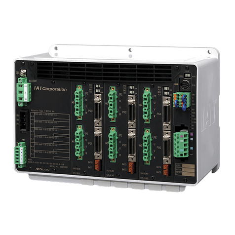
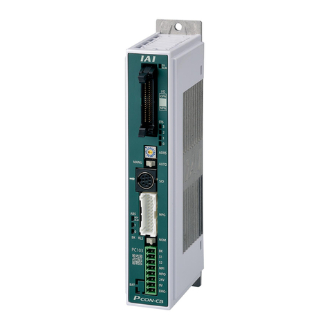
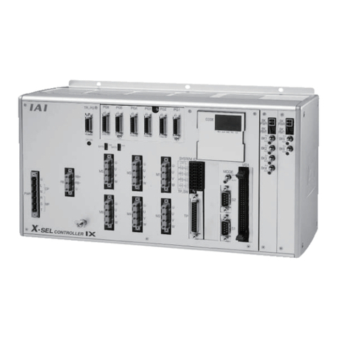
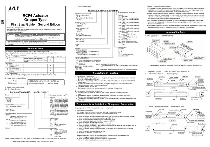
IAI X-SEL User manual

Operation Manual Nineteenth Edition
XSEL Controller
P/Q/PCT/QCT Type


& "% &
! ,"( "% #(%&! "(% #%"('
& #%'"! !( &%& !&&%,!"% '"! ' & '" "#%' '& #%"(' &,
&( & ' "#%'"! #%"(% &'%('(% ! !'!! #%"(%
"% ' "#%'"! % '& !( %(, ! (, (!%&'! ' '" "#%' '& #%"('
&,
!"& ! '& #%"(' # !(& ' #%'"! !( "% '& #%"('
"% ' "#%'"! " '& #%"(' #%!' "(' ' !&&%, &'"!& ! ' #%'"! !( "%
&#, ' (&! ' #%&"! " #('%
'% %! '%"( '& !( # '& #%'"! !( ' ! &" '' ' "#%'"% "'&
#%"(' ! % ' *!)% !&&%,
#"%'!'
- & #%'"! !( & "%!
- #%"(' !!"' "#%' ! !, *, (!&& +#%&&, &# ! '& #%'"!
!( & &&( !" %&#"!&', "% ' "('" " !, "#%'"! !"' &#
%!
- !"% '"! "!'! ! '& #%'"! !( & &(' '" ! *'"(' !"' "% '
#(%#"& " #%"(' #%") !'
- ,"( ) !, $(&'"! "% " !' %%! ' "!'!' " '& !( #& "!''
' && " !% ,"(
- &! "% "#,! "% #%' " '& #%'"! !( *'"(' #% &&"! & #%"'
- " #!, ! & ! & " #%"('& ! '% %& " " #!, &"*! ! '
&!'!& % %&'% '% %&

CAUTION
Operator Alarm on Low Battery Voltage
This controller is equipped with the following backup batteries for retention of data in the event of power failure:
[1] System-memory backup battery
For retention of position data, global variables/flags, error list, strings, etc.
[2] Absolute-encoder backup battery (optional)
For retention of rotation data (when an absolute encoder is used)
Since these batteries are not rechargeable, they will be eventually consumed. Unless the batteries are replaced
in a timely manner, the voltage will drop to a level where the data can no longer be retained. If a power failure
occurs in this condition, the data will be lost. (The life of each battery varies depending on the operating time.)
Once the data is lost, the controller will not operate normally the next time the power is turned on, and recovery
will take time.
(Reference)
System-memory backup battery --- An alarm occurs when the voltage drops to approx. 2.6 V and data backup
becomes no longer possible at a battery voltage of approx. 2.3 V (rated
voltage: 3.0 V).
Absolute-encoder backup battery --- An alarm occurs when the voltage drops to approx. 3.2 V and data backup
becomes no longer possible at a battery voltage of approx. 2.7 V (rated
voltage: 3.6 V).
To prevent this problem, this controller can output a low battery voltage alarm from its I/O port.
To output this alarm signal from an I/O port, you must set the applicable I/O parameter.
Alarm output for the system-memory backup battery
Set I/O parameter No. 59 to “1” --- Output port No. 313 (*) will be assigned as a dedicated port.
Alarm output for the absolute-encoder backup battery
Set I/O parameter No. 60 to “1” --- Output port No. 314 (*) will be assigned as a dedicated port.
(*) Once set as an alarm output port, the applicable port can no longer be used as a general-purpose
port.
It is recommended that this function be utilized to prevent unnecessary problems resulting from low battery
voltage (consumption of battery life).
In particular, the person in charge of system design should utilize this function to provide a design means for
issuing an operator alarm using an output signal from an I/O port, while the person in charge of electrical design
should provide an electrical means for achieving the same effect.
For the battery replacement procedure, refer to the applicable section in the operating manual.
It is recommended that you always backup the latest data to a PC in case of voltage drop in the system-memory
battery or unexpected controller failure.
About teaching pendant and PC software
Q/QCT type controllers only support the following teaching pendant and PC software:
Teaching pendant: IA-T-XA (ANSI type)
PC software: IA-101-XA-MW (Supplied with category 4 cable)

CAUTION
ence has to do with the specific circuit
the input voltage and number of external regenerative
at least 40 seconds before reconnecting the power.
Drive-Source Cutoff Relay Error (Detection of Fused Relay: E6D)
As a condition limited to XSEL-P/PCT type controllers of standard single-phase specification, a “drive-source cutoff
relay error (E6D)” may generate if the power is turned off and then turned on again (reconnected) too quickly.
This error indicates that the internal relay has fused, and its occurr
configuration of the above controller type.
Although the specific wait time varies depending on
resistors connected, as a general guide wait for
Regarding Operation of High Speed Cartesian Robot CT4
It is necessary to declare specific functions in SEL language program for the operation.
[Refer to Appendix Operation of High Speed Cartesian Robot (CT4) for the details.]
Power Supply/Shutoff and Input of Emergency Stop
1) Do not turn on/off the power frequently.
2) Do not construct the system that allows frequent input of emergency stop or turning on/off of the drive power.
In the power source of the controller, there is a capacitor that allows large in-rush current (charge current) to flow
transiently when the power is turned on.
Therefore, it may cause early degradation on the internal components if turning on/off of the power and turning
on/off of the drive power due to emergency stop input are conducted frequently.
Contact IAI in case it is necessary to establish a system to allow frequent turning on/off of the power inevitably.

CAUTION
Note on Controller with Expanded CPU Unit Memory
* The controller with gateway function comes with an expanded memory in the CPU unit.
For a controller with expanded CPU unit memory, use the PC software or teaching pendant of an applicable
version as specified below.
Teaching tool Version
XSEL PC software V7.2.0.0 or later
Teaching pendant SEL-T/TD V1.01 or later
[How to check if the controller memory has been expanded]
Check in the PC software (Ver. 6.0.0.0 or later) by displaying the ROM version information (Controller (C)
ROM Version Information (V)), or on the teaching pendant (IA-T-X, IA-T-XD: Ver. 1.21 or later; SEL-T, SEL-TD:
Ver. 1.00 or later) by displaying the main CPU firmware version information (Moni Ver Main).
Expanded memory: As shown below, “Main (FROM32M)” is shown in the PC software. On the teaching
pendant screen, “Main (FROM32M)” is shown.
Checking in PC software
Checking in teaching pendant

Safety Guide
³6DIHW\*XLGH´KDVEHHQZULWWHQWRXVHWKHPDFKLQHVDIHO\DQGVRSUHYHQWSHUVRQDOLQMXU\RUSURSHUW\
GDPDJHEHIRUHKDQG0DNHVXUHWRUHDGLWEHIRUHWKHRSHUDWLRQRIWKLVSURGXFW
Safety Precautions for Our Products
7KHFRPPRQVDIHW\SUHFDXWLRQVIRUWKHXVHRIDQ\RIRXUURERWVLQHDFKRSHUDWLRQ
1R2SHUDWLRQ
'HVFULSWLRQ'HVFULSWLRQ
0RGHO
6HOHFWLRQ
Ɣ7KLVSURGXFWKDVQRWEHHQSODQQHGDQGGHVLJQHGIRUWKHDSSOLFDWLRQZKHUH
KLJKOHYHORIVDIHW\LVUHTXLUHGVRWKHJXDUDQWHHRIWKHSURWHFWLRQRI
KXPDQOLIHLVLPSRVVLEOH$FFRUGLQJO\GRQRWXVHLWLQDQ\RIWKHIROORZLQJ
DSSOLFDWLRQV
0HGLFDOHTXLSPHQWXVHGWRPDLQWDLQFRQWURORURWKHUZLVHDIIHFWKXPDQ
OLIHRUSK\VLFDOKHDOWK
0HFKDQLVPVDQGPDFKLQHU\GHVLJQHGIRUWKHSXUSRVHRIPRYLQJRU
WUDQVSRUWLQJSHRSOH)RUYHKLFOHUDLOZD\IDFLOLW\RUDLUQDYLJDWLRQIDFLOLW\
,PSRUWDQWVDIHW\SDUWVRIPDFKLQHU\6DIHW\GHYLFHHWF
Ɣ'RQRWXVHWKHSURGXFWRXWVLGHWKHVSHFLILFDWLRQV)DLOXUHWRGRVRPD\
FRQVLGHUDEO\VKRUWHQWKHOLIHRIWKHSURGXFW
Ɣ'RQRWXVHLWLQDQ\RIWKHIROORZLQJHQYLURQPHQWV
/RFDWLRQZKHUHWKHUHLVDQ\LQIODPPDEOHJDVLQIODPPDEOHREMHFWRU
H[SORVLYH
3ODFHZLWKSRWHQWLDOH[SRVXUHWRUDGLDWLRQ
/RFDWLRQZLWKWKHDPELHQWWHPSHUDWXUHRUUHODWLYHKXPLGLW\H[FHHGLQJ
WKHVSHFLILFDWLRQUDQJH
/RFDWLRQZKHUHUDGLDQWKHDWLVDGGHGIURPGLUHFWVXQOLJKWRURWKHUODUJH
KHDWVRXUFH
/RFDWLRQZKHUHFRQGHQVDWLRQRFFXUVGXHWRDEUXSWWHPSHUDWXUH
FKDQJHV
/RFDWLRQZKHUHWKHUHLVDQ\FRUURVLYHJDVVXOIXULFDFLGRUK\GURFKORULF
DFLG
/RFDWLRQH[SRVHGWRVLJQLILFDQWDPRXQWRIGXVWVDOWRULURQSRZGHU
/RFDWLRQVXEMHFWWRGLUHFWYLEUDWLRQRULPSDFW
Ɣ)RUDQDFWXDWRUXVHGLQYHUWLFDORULHQWDWLRQVHOHFWDPRGHOZKLFKLV
HTXLSSHGZLWKDEUDNH,IVHOHFWLQJDPRGHOZLWKQREUDNHWKHPRYLQJSDUW
PD\GURSZKHQWKHSRZHULVWXUQHG2))DQGPD\FDXVHDQDFFLGHQWVXFK
DVDQLQMXU\RUGDPDJHRQWKHZRUNSLHFH

No. Operation
Description Description
2 Transportation ƔWhen carrying a heavy object, do the work with two or more persons or
utilize equipment such as crane.
ƔWhen the work is carried out with 2 or more persons, make it clear who is
to be the leader and who to be the follower(s) and communicate well with
each other to ensure the safety of the workers.
ƔWhen in transportation, consider well about the positions to hold, weight
and weight balance and pay special attention to the carried object so it
would not get hit or dropped.
ƔTransport it using an appropriate transportation measure.
The actuators available for transportation with a crane have eyebolts
attached or there are tapped holes to attach bolts. Follow the instructions
in the operation manual for each model.
ƔDo not step or sit on the package.
ƔDo not put any heavy thing that can deform the package, on it.
ƔWhen using a crane capable of 1t or more of weight, have an operator
who has qualifications for crane operation and sling work.
ƔWhen using a crane or equivalent equipments, make sure not to hang a
ORDGWKDWZHLJKVPRUHWKDQWKHHTXLSPHQW¶VFDSDELOLW\OLPLW
ƔUse a hook that is suitable for the load. Consider the safety factor of the
hook in such factors as shear strength.
ƔDo not get on the load that is hung on a crane.
ƔDo not leave a load hung up with a crane.
ƔDo not stand under the load that is hung up with a crane.
3 Storage and
Preservation
ƔThe storage and preservation environment conforms to the installation
environment. However, especially give consideration to the prevention of
condensation.
ƔStore the products with a consideration not to fall them over or drop due to
an act of God such as earthquake.
4 Installation
and Start
(1) Installation of Robot Main Body and Controller, etc.
ƔMake sure to securely hold and fix the product (including the work part). A
fall, drop or abnormal motion of the product may cause a damage or injury.
Also, be equipped for a fall-over or drop due to an act of God such as
earthquake.
ƔDo not get on or put anything on the product. Failure to do so may cause
an accidental fall, injury or damage to the product due to a drop of
anything, malfunction of the product, performance degradation, or
shortening of its life.
ƔWhen using the product in any of the places specified below, provide a
sufficient shield.
1) Location where electric noise is generated
2) Location where high electrical or magnetic field is present
3) Location with the mains or power lines passing nearby
4) Location where the product may come in contact with water, oil or
chemical droplets

No. Operation
Description Description
(2) Cable Wiring
Ɣ8VHRXUFRPSDQ\¶VJHQXLQHFDEOHVfor connecting between the actuator
and controller, and for the teaching tool.
ƔDo not scratch on the cable. Do not bend it forcibly. Do not pull it. Do not
coil it around. Do not insert it. Do not put any heavy thing on it. Failure to
do so may cause a fire, electric shock or malfunction due to leakage or
continuity error.
ƔPerform the wiring for the product, after turning OFF the power to the unit,
so that there is no wiring error.
ƔWhen the direct current power (+24V) is connected, take the great care of
the directions of positive and negative poles. If the connection direction is
not correct, it might cause a fire, product breakdown or malfunction.
ƔConnect the cable connector securely so that there is no disconnection or
looseness. Failure to do so may cause a fire, electric shock or malfunction
of the product.
ƔNever cut and/or reconnect the cables supplied with the product for the
purpose of extending or shortening the cable length. Failure to do so may
cause the product to malfunction or cause fire.
4 Installation
and Start
(3) Grounding
ƔThe grounding operation should be performed to prevent an electric shock
or electrostatic charge, enhance the noise-resistance ability and control
the unnecessary electromagnetic radiation.
ƔFor the ground terminal on the AC power cable of the controller and the
grounding plate in the control panel, make sure to use a twisted pair cable
with wire thickness 0.5mm2(AWG20 or equivalent) or more for grounding
work. For security grounding, it is necessary to select an appropriate wire
thickness suitable for the load. Perform wiring that satisfies the
specifications (electrical equipment technical standards).
ƔPerform Class D Grounding (former Class 3 Grounding with ground
resistance 100:or below).

No. Operation
Description Description
4 Installation
and Start
(4) Safety Measures
ƔWhen the work is carried out with 2 or more persons, make it clear who is
to be the leader and who to be the follower(s) and communicate well with
each other to ensure the safety of the workers.
ƔWhen the product is under operation or in the ready mode, take the safety
measures (such as the installation of safety and protection fence) so that
nobody can enter the area within tKHURERW¶VPRYDEOHUDQJH:KHQWKH
robot under operation is touched, it may result in death or serious injury.
Ɣ0DNHVXUHWRLQVWDOOWKHHPHUJHQF\VWRSFLUFXLWVRWKDWWKHXQLWFDQEH
VWRSSHGLPPHGLDWHO\LQDQHPHUJHQF\GXULQJWKHXQLWRSHUDWLRQ
Ɣ7DNHWKHVDIHW\PHDVXUHQRWWRVWDUWXSWKHXQLWRQO\ZLWKWKHSRZHUWXUQLQJ
ON. Failure to do so may start up the machine suddenly and cause an
LQMXU\RUGDPDJHWRWKHSURGXFW
ƔTake the safety measure not to start up the machine only with the
HPHUJHQF\VWRSFDQFHOODWLRQRUUHFRYHU\DIWHUWKHSRZHUIDLOXUH)DLOXUHWR
do so may result in an electric shock or injury due to unexpected power
input.
Ɣ:KHQWKHLQVWDOODWLRQRUDGMXVWPHQWRSHUDWLRQLVWREHSHUIRUPHGJLYH
FOHDUZDUQLQJVVXFKDV³8QGHU2SHUDWLRQ'RQRWWXUQ21WKHSRZHU´HWF
Sudden power input may cause an electric shock or injury.
ƔTake the measure so that the work part is not dropped in power failure or
HPHUJHQF\VWRS
Ɣ:HDUSURWHFWLRQJORYHVJRJJOHRUVDIHW\VKRHVDVQHFHVVDU\WRVHFXUH
safety.
Ɣ'RQRWLQVHUWDILQJHURUREMHFWLQWKHRSHQLQJVLQWKHSURGXFW)DLOXUHWRGR
VRPD\FDXVHDQLQMXU\HOHFWULFVKRFNGDPDJHWRWKHSURGXFWRUILUH
Ɣ:KHQUHOHDVLQJWKHEUDNHRQDYHUWLFally oriented actuator, exercise
SUHFDXWLRQQRWWRSLQFK\RXUKDQGRUGDPDJHWKHZRUNSDUWVZLWKWKH
DFWXDWRUGURSSHGE\JUDYLW\
7HDFKLQJƔWhen the work is carried out with 2 or more persons, make it clear who is
to be the leader and who to be the follower(s) and communicate well with
each other to ensure the safety of the workers.
Ɣ3HUIRUPWKHWHDFKLQJRSHUDWLRQIURPRXWside the safety protection fence, if
possible. In the case that the operaWLRQLVWREHSHUIRUPHGXQDYRLGDEO\
inside the safety protection fence,SUHSDUHWKH³6WLSXODWLRQVIRUWKH
2SHUDWLRQ´DQGPDNHVXUHWKDWDOOWKHZRUNHUVDFNQRZOHGJHDQG
understand them well.
ƔWhen the operation is to be performed inside the safety protection fence,
WKHZRUNHUVKRXOGKDYHDQHPHUJHQF\VWop switch at hand with him so that
WKHXQLWFDQEHVWRSSHGDQ\WLPHLQDQHPHUJHQF\
ƔWhen the operation is to be performed inside the safety protection fence,
LQDGGLWLRQWRWKHZRUNHUVDUUDQJHa watchman so that the machine can
EHVWRSSHGDQ\WLPHLQDQHPHUJHQF\$OVRNHHSZDWFKRQWKHRSHUDWLRQ
so that any third person can not operate the switches carelessly.
Ɣ3ODFHDVLJQ³8QGHU2SHUDWLRQ´DWWKHSRVLWLRQHDV\WRVHH
Ɣ:KHQUHOHDVLQJWKHEUDNHRQDYHUWLFally oriented actuator, exercise
SUHFDXWLRQQRWWRSLQFK\RXUKDQGRUGDPDJHWKHZRUNSDUWVZLWKWKH
DFWXDWRUGURSSHGE\JUDYLW\
* Safety protection Fence : In the case that there is no safety protection
IHQFHWKHPRYDEOHUDQJHVKRXOGEHLQGLFDWHG
No. Operation
Description Description
6 Trial Operation ƔWhen the work is carried out with 2 or more persons, make it clear who is
to be the leader and who to be the follower(s) and communicate well with
each other to ensure the safety of the workers.
ƔAfter the teaching or programming operation, perform the check operation
one step by one step and then shift to the automatic operation.
ƔWhen the check operation is to be performed inside the safety protection
fence, perform the check operation using the previously specified work
procedure like the teaching operation.
ƔMake sure to perform the programmed operation check at the safety
speed. Failure to do so may result in an accident due to unexpected
motion caused by a program error, etc.
ƔDo not touch the terminal block or any of the various setting switches in
the power ON mode. Failure to do so may result in an electric shock or
malfunction.
7 Automatic
Operation
ƔCheck before starting the automatic operation or rebooting after operation
stop that there is nobody in the safety protection fence.
ƔBefore starting automatic operation, make sure that all peripheral
equipment is in an automatic-operation-ready state and there is no alarm
indication.
ƔMake sure to operate automatic operation start from outside of the safety
protection fence.
ƔIn the case that there is any abnormal heating, smoke, offensive smell, or
abnormal noise in the product, immediately stop the machine and turn
OFF the power switch. Failure to do so may result in a fire or damage to
the product.
ƔWhen a power failure occurs, turn OFF the power switch. Failure to do so
may cause an injury or damage to the product, due to a sudden motion of
the product in the recovery operation from the power failure.

No. Operation
Description Description
8 Maintenance
and Inspection
ƔWhen the work is carried out with 2 or more persons, make it clear who is
to be the leader and who to be the follower(s) and communicate well with
each other to ensure the safety of the workers.
ƔPerform the work out of the safety protection fence, if possible. In the case
that the operation is to be performed unavoidably inside the safety
SURWHFWLRQIHQFHSUHSDUHWKH³6WLSXODWLRQVIRUWKH2SHUDWLRQ´DQGPDNH
sure that all the workers acknowledge and understand them well.
ƔWhen the work is to be performed inside the safety protection fence,
basically turn OFF the power switch.
ƔWhen the operation is to be performed inside the safety protection fence,
the worker should have an emergency stop switch at hand with him so that
the unit can be stopped any time in an emergency.
ƔWhen the operation is to be performed inside the safety protection fence,
in addition to the workers, arrange a watchman so that the machine can
be stopped any time in an emergency. Also, keep watch on the operation
so that any third person can not operate the switches carelessly.
Ɣ3ODFHDVLJQ³8QGHU2SHUDWLRQ´DWWKHSRVLWLRQHDV\WRVHH
ƔFor the grease for the guide or ball screw, use appropriate grease
according to the Operation Manual for each model.
ƔDo not perform the dielectric strength test. Failure to do so may result in a
damage to the product.
ƔWhen releasing the brake on a vertically oriented actuator, exercise
precaution not to pinch your hand or damage the work parts with the
actuator dropped by gravity.
ƔThe slider or rod may get misaligned OFF the stop position if the servo is
turned OFF. Be careful not to get injured or damaged due to an
unnecessary operation.
ƔPay attention not to lose the cover or untightened screws, and make sure
to put the product back to the original condition after maintenance and
inspection works.
8VHLQLQFRPSOHWHFRQGLWLRQPD\FDXVHGDPDJHWRWKHSURGXFWRUDQLQMXU\
6DIHW\SURWHFWLRQ)HQFH,QWKHFDVH that there is no safety protection
fence, the movable range should be indicated.
9 Modification
and Dismantle
ƔDo not modify, disassemble, assemble or use of maintenance parts not
specified based at your own discretion.
10 Disposal ƔWhen the product becomes no longer usable or necessary, dispose of it
properly as an industrial waste.
ƔWhen removing the actuator for disposal, pay attention to drop of
components when detaching screws.
ƔDo not put the product in a fire when disposing of it.
The product may burst or generate toxic gases.
11 Other ƔDo not come close to the product or the harnesses if you are a person
who requires a support of medical devices such as a pacemaker. Doing so
may affect the performance of your medical device.
Ɣ6HH2YHUVHDV6SHFLILFDWLRQV&RPSliance Manual to check whether
complies if necessary.
ƔFor the handling of actuators and controllers, follow the dedicated
operation manual of each unit to ensure the safety.

Alert Indication
7KHVDIHW\SUHFDXWLRQVDUHGLYLGHGLQWR³'DQJHU´³:DUQLQJ´³&DXWLRQ´DQG³1RWLFH´DFFRUGLQJWRWKH
ZDUQLQJOHYHODVIROORZVDQGGHVFULEHGLQWKH2SHUDWLRQ0DQXDOIRUHDFKPRGHO
/HYHO'HJUHHRI'DQJHUDQG'DPDJH6\PERO
'DQJHU7KLVLQGLFDWHVDQLPPLQHQWO\KD]DUGRXVVLWXDWLRQZKLFKLIWKH
SURGXFWLVQRWKDQGOHGFRUUHFWO\ZLOOUHVXOWLQGHDWKRUVHULRXVLQMXU\ 'DQJHU
:DUQLQJ7KLVLQGLFDWHVDSRWHQWLDOO\KD]DUGRXVVLWXDWLRQZKLFKLIWKHSURGXFW
LVQRWKDQGOHGFRUUHFWO\FRXOGUHVXOWLQGHDWKRUVHULRXVLQMXU\ :DUQLQJ
&DXWLRQ
7KLVLQGLFDWHVDSRWHQWLDOO\KD]DUGRXVVLWXDWLRQZKLFKLIWKHSURGXFW
LVQRWKDQGOHGFRUUHFWO\PD\UHVXOWLQPLQRULQMXU\RUSURSHUW\
GDPDJH
&DXWLRQ
1RWLFH7KLVLQGLFDWHVORZHUSRVVLELOLW\IRUWKHLQMXU\EXWVKRXOGEHNHSWWR
XVHWKLVSURGXFWSURSHUO\ 1RWLFH

<;
" #!*''I%!&%$(%#&""*)%&&Q'!%&" #!!(
4I9;A@5''&#%")&#%',

91;9>
R!&!!!##'"!&,&' (&!'('"%&!"!'%"%&!"%%'*%!"%"!!'"!"
,(&(!+#'#%" &&(&&"!!'"%#""%"!''"%)!%(!*,
&,&' &&'"!+#!&#%"'!!"&'!"% '"!%(,'""!!''&
#%"#%,
!(&"%K!!&4(&'&%).5
:"!"'''+'&!#"!'
;"!"'''!!"%'*&' <"!"'#('*'&'%"!"%
="!"'''%)'(%!!"%'
&!#"!'
?"!"'#!%"#),"'"!'""%(''
>R!+!'#%") "%'&
!"!"''!&"!''""''
Q'!
4#!"*%5
(!""&,
&(%,
"!"'(&&#%'(*%
'+&%$(!',

@"!"'''''!"%!!'%"%+'(R!(!!'#
%'!%"+',4&"'''*!"'" '""'('*!!'5
A"!"'(&'&'""(#, "%'!
?91"'&#!''%
B "!"',&!!&'"'%*'%('!&
''%'&'%"!'%
:9*,&(&%""''&,'"+&!!',
Q'!%&'%('(%"
&'!%&'%('(%"
*)%,#!!"!'
!('(%%!',#"
O"%""'&
"!!''" ")!#%'"!'('"%&,&' *!)',%)%#'!!"&''
&"'&%&(''"%&!' ,%")%' " ! Y'%&"
%*&'%"!,%" !''%""'"%!&!!',%+',(&!'&',#"
##'"!
'%
"*%!
Q!!&4'5
('
&"%! '%4R!'
&!''& '%&
%(&,'&(%%"(!!&!
!&'" !'!'&#"'
&!!&5
")%
Q
%"''),%
Q!!4"##%7'!5
")%

#"%'!'C&"%&
('"!
: &(%'"%'&#%'"!!('"!&(%'"%%'(&"'&#%"('
; &#%'"!!(!#%'"%!*" (&'!"'(&"%%#%"(*'"('#% &&"!
< !,!!"#%'"!"%"'%(&!"'&#!'&#%'"!!(&"("!&%
#%"'! (&'!"''' #'&"!"'''#%" &%&('!%" !,!!"#%'"!"%
"'%(&!"'&#!'&#%'"!!(&+(%" '&"#"*%%!',
= "!'!'&"'&#%'"!!(%&(''"!*'"('!"'"%'#(%#"&" "'"!"%
#%") !'
6,"()#(%&'&"'*%C
''!'&'(#"'#%"('!'%!!!,"'&#% '%&&(%'"(#'
#% '%&
> %'!&#'"!&&%!'& !( ,!"'##,'"(&'" "&
I %!,'"!
'&#%"('&"(!!!%"(&&'' ','(%!"'#"*%&*'"'#%"('&*
&#"*%&*'&"$(# !'!)&"!!''"'#%"('"%(!#(#"*%&
%" ''%"(''&4`!%"(&&''b%%&'"&'('"!*%'#%"('&!%'!!
!"% "(!'"'"%& "&!'"%&"'%*&%'"(&%"%",!(%,5


Table of Contents
Introduction........................................................................................................................1
Part 1 Installation...........................................................................................................3
Chapter 1 Safety Precautions............................................................................................................... 3
Chapter 2 Warranty .............................................................................................................................. 4
1. Warranty Period ................................................................................................................... 4
2. Scope of the Warranty ......................................................................................................... 4
3. Honoring the Warranty......................................................................................................... 4
4. Limited Liability .................................................................................................................... 4
5. Conditions of Conformance with Applicable Standards/Regulations, Etc.,
and Applications................................................................................................................... 5
6. Other Items Excluded from Warranty................................................................................... 5
Chapter 3 Installation Environment and Selection of Auxiliary Power Devices .................................... 6
1. Installation Environment....................................................................................................... 6
2. Heat Radiation and Installation ............................................................................................ 7
3. Selection of Auxiliary Power Devices................................................................................... 8
4. Noise Control Measures and Grounding............................................................................ 13
Chapter 4 Name and Function of Each Part....................................................................................... 16
1. Front View of Controller ..................................................................................................... 16
2. Explanation of Codes Displayed on the Panel Window ..................................................... 29
Chapter 5 Specifications..................................................................................................................... 33
1. Controller Specifications .................................................................................................... 33
2. External I/O Specifications................................................................................................. 37
3. Power-Source Capacity and Heat Output.......................................................................... 41
4. External Dimensions .......................................................................................................... 45
Chapter 6 Safety Circuit...................................................................................................................... 53
1. Items to Notes.................................................................................................................... 53
2. Safety Circuit for P/PCT Type (Standard Specification) Controller.................................... 54
3. Safety Circuit for Q/QCT Type (Global Specification) Controller ....................................... 56
4. Safety Circuit Timing Charts for Q/QCT type SEL Controller ............................................ 61
Chapter 7 System Setup..................................................................................................................... 70
1. Connection Method of Controller and Actuator.................................................................. 70
2. I/O Connection Diagram .................................................................................................... 73
3. Multi-point DIO Board ........................................................................................................ 79
Chapter 8 How to Perform An Absolute Encoder Reset (Absolute Specification) .............................. 85
1. Single Axis, Orthogonal Axis and Rotating Axis ................................................................ 85
2. How to Perform Absolute Reset on ZR Unit (Absolute Type Only).................................... 90
Chapter 9 Maintenance .................................................................................................................... 105
1. Inspection Points.............................................................................................................. 105
2. Spare Consumable Parts................................................................................................. 105
3. Replacement Procedure for System-Memory Backup Battery ........................................ 106
4. Replacement Procedure for Absolute-Data Backup Battery............................................ 109

Part 2 Operation ........................................................................................................111
Chapter 1 Operation ......................................................................................................................... 111
1. Starting a Program by Auto-Start via Parameter Setting ................................................. 112
2. Starting via External Signal Selection .............................................................................. 113
3. Drive-Source Recovery Request and Operation-Pause Reset Request ......................... 115
Part 3 Controller Data Structure ................................................................................116
Chapter 1 How to Save Data ............................................................................................................ 117
1. Factory Settings: When the System-Memory Backup Battery is Used ............................ 117
2. When the System-Memory Backup Battery is Not Used ................................................. 119
3. Points to Note .................................................................................................................. 121
Chapter 2 XSEL Language Data ...................................................................................................... 123
1. Values and Symbols Used in SEL Language .................................................................. 123
1.1 List of Values and Symbols Used ........................................................................... 123
1.2 I/O Ports.................................................................................................................. 124
1.3 Virtual I/O Ports....................................................................................................... 125
1.4 Flags ....................................................................................................................... 127
1.5 Variables ................................................................................................................. 128
1.6 Tags ........................................................................................................................ 131
1.7 Subroutines............................................................................................................. 132
1.8 Symbols .................................................................................................................. 133
1.9 Character-String Literals ......................................................................................... 133
1.10 Axis Specification.................................................................................................... 134
2. Position Part..................................................................................................................... 136
3. Command Part................................................................................................................. 137
3.1 SEL language Structure.......................................................................................... 137
3.2 Extension Condition ................................................................................................ 138
Part 4 Commands .....................................................................................................139
Chapter 1 List of SEL Language Command Codes.......................................................................... 139
Chapter 2 Explanation of Commands............................................................................................... 151
1. Commands....................................................................................................................... 151
1.1 Variable Assignment ............................................................................................... 151
1.2 Arithmetic Operation ............................................................................................... 153
1.3 Function Operation ................................................................................................. 156
1.4 Logical Operation.................................................................................................... 159
1.5 Comparison Operation............................................................................................ 162
1.6 Timer....................................................................................................................... 163
1.7 I/O, Flag Operation ................................................................................................. 166
1.8 Program Control...................................................................................................... 177
1.9 Task Management .................................................................................................. 180
1.10 Position Operation .................................................................................................. 185
1.11 Actuator Control Declaration................................................................................... 200
1.12 Actuator Control Command .................................................................................... 220
Other manuals for X-SEL
5
Table of contents
Other IAI Controllers manuals

IAI
IAI EleCylinder Series User manual

IAI
IAI ASEP User manual

IAI
IAI RCON-PC User manual

IAI
IAI ROBO Cylinder RCP2 Series User manual

IAI
IAI SCON-CA User manual

IAI
IAI Msep User manual

IAI
IAI ERC2 Installation manual

IAI
IAI ROBO Cylinder RCP2 Series User manual

IAI
IAI ACON-C Series User manual

IAI
IAI ROBO Cylinder RCS4- SA4C User manual