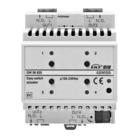
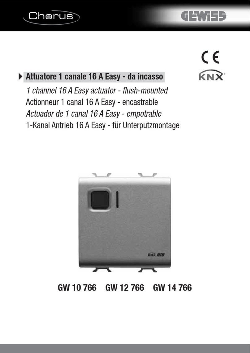
Gewiss Chorus GW 10 766 User manual

1
Easy 1 channel switch actuator 16A
GW 10 766
GW 12 766
GW 14 766
Technical Manual

2
Summary
1Introduction................................................................................................................................................. 3
2Application.................................................................................................................................................. 4
2.1Limits to the associations................................................................................................................... 4
2.2Block diagrams .................................................................................................................................. 4
3“Settings” menu.......................................................................................................................................... 5
3.1Parameters ........................................................................................................................................ 5
3.2Communication objects ..................................................................................................................... 6
4“Timed execution” menu............................................................................................................................. 7
4.1Parameters ........................................................................................................................................ 7
4.2Communication objects ..................................................................................................................... 8
5“Priority commands execution” menu......................................................................................................... 9
5.1Parameters ........................................................................................................................................ 9
5.2Communication objects ................................................................................................................... 10
6“Scene Management” menu..................................................................................................................... 11
6.1Parameters ...................................................................................................................................... 11
6.2Communication objects ................................................................................................................... 12

3
1 Introduction
This manual describes the functions of the device named GW1x766 “Easy 1 channel switch actuator 16A”
and how to use the ETS configuration software to change the settings and configurations.

4
2 Application
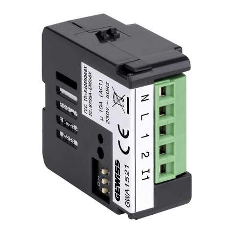
The Easy 1 channel switch actuator 16A is used to activate/deactivate an electric load using a 16 A relay.
The device has 1 channel with an output that has a changeover contact to which two terminals are
connected, one with a normally open (NO) contact function and the other with a normally closed (NC)
functions to which it is possible to connect the load according to requirements. The device is fitted with 1
front button to control the relay that commands the load, 1 green LED that indicates the activated output
status (NO contact closed and NC contact open) and 1 amber LED for night lighting of the front button. On
the back of the device there is a button and red physical address programming LED.
The device must be configured using the ETS software to perform the functions listed below:
•switching ON/OFF
•priority commands
•timed activation (staircase light function)
•scenes
2.1 Limits to the associations
Maximum number of group addresses: 115
Maximum number of logical associations: 115
This means that it could be possible to define maximum 115 group addresses and realize maximum 115
associations between group addresses and communication objects.
2.2 Block diagrams
The status of the actuator relay depends on the communication objects that are activated. For all the
foreseen operating modes, the Priority Command object has maximum priority. The lowest priority
communication objects are: the Switch object, the Timed switch object and the Scene object (see Diag. 2.1).
Diag. 2.1
Timed switch
object
Switch
object
Rela
y
Status
object
Priority command
object
Scene
object

5
3 “Settings” menu
Here it is possible to configure the programming mode between ETS mode (S-Mode) and Easy mode by the
Easy controller software (Kit GW90837, Kit GW90838, GW90840) and enable the night localisation of the
actuator (see Diag 3.1).
Diag. 3.1
3.1 Parameters
¾3.1.1 Programming mode
This parameter determines the programming mode of the device:
•ETS mode
Select this value if you want to configure the device with ETS (S-Mode); all the configuration parameters
are now visible.
•Easy mode
Select this value if you want to configure the device with the Easy controller software.
Remember to download the application program with this value selected before using the device by the
Easy controller software if you have already used the device in an ETS project.

6
¾3.1.2 Night lighting
This is to activate/deactivate the lighting function of the front yellow amber coloured LEDs; the settings
are:
•deactivated
The front yellow amber coloured LED will never be working, therefore when the load is deactivated (open
if NO/closed if NC) the front indicator light will not be backlit.
•active
The front yellow amber coloured LED is working when the load is deactivated (open if NO/closed if NC);
in this case, the front indicator light is backlit by the yellow amber LED indicating that the load status is
deactivated, in the case of lack of light in the environment, it also acts as a device localisation light.
3.2 Communication objects
The Settings menu makes the following communication objects visible (see Diag. 3.2.):
Diag. 3.2
¾3.2.1 Switch
When the device receives a telegram on this communication object, according to the command received,
it will switch the changeover contact following the configured settings and, through the Status object, it
will send the load activated/deactivated status information.
When the device receives a switch ON command, the changeover contact is immediately switched
(closed if NO/open if NC); on receiving a switch OFF command, it returns to its normal condition (open if
NO/closed if NC).
The enabled flags are C (communication), W (written by bus) .
The standard format of the object is 1.001 DPT_Switch, the size of the object is 1 bit and the commands
it interprets are switch ON/OFF.
¾3.2.2 Status
Using this communication object, the device communicates the activated/deactivated status of the
connected load.
When the device switch ON the load command (close the NO contact/open the NC contact), immediately
sends the load activated status information by a bus telegram with a "1" logic value; vice versa, when the
device switch OFF the load command (open the NO contact/close the NC contact), immediately sends
the load deactivated status information by a bus telegram with a "0" logic value.
The activated flags are C (communication), R (read by bus) and T (transmission) .
The standard format of the object is 1.001 DPT_Switch, the size of the object is 1 bit and the information
it contains is load status ON/OFF.
7
4 “Timed execution” menu
The Timed execution menu lists all the parameters needed to enable and configure the timed activation of
the relay (staircase light function) as shown in Diag. 4.1.
Diag. 4.1
4.1 Parameters
¾4.1.1 Activate function
Here you can enable and configure the function and make visibles the Activation time parameter, the
Warning time parameter and the relative Timed switch communication object. The settings are:
•yes
The function can be activated by the Timed switch communication object and it is possible to activate it
using a bus command; a reception of an ON/OFF switching command on the Switching communication
object is immediately executed and the timed activation finishes.
•no
The function is not enabled and consequently the various parameters and communication object are not
visible.

8
¾4.1.2 Activation time
Here you can set the activation time value. It is possible to set a value between 1 second and 24 hours.
When the device receives the START timed activation command, it switches the relay (close NO contact
/ open NC contact) and at the end of the activation time setting, it automatically switches the contact
back to normal conditions (open NO contact / close NC contact); when it receives a STOP activation
time command, if the function is activated, the device will stop the timer and switch the contact back to
normal conditions (open NO contact / close NC contact). see diag. 4.2.
Diag. 4.2
The activation time is resettable so, if during the activation time the device receives a START
temporization command, the activation time will be reset and the load will remain activated; in theory this
can occur many times, as there is no limit to the number of reset commands.
¾5.1.6 Warning time
Here you can set the warning time before the deactivation of the timed activation, upon which the device
will consequently signal the imminent termination of the function; the values are “no warning”, 15 s, 30 s
and1 min.
4.2 Communication objects
The Timed execution menu makes the following communication object visible (see Diag. 4.3.):
Diag. 4.3
¾4.2.1 Timed switch
When the device receives a telegram on this communication object, according to the command received
(START or STOP temporization), it will switch the changeover contacts and, through the Status object, it
will send the load activated/deactivated status information.
When the device receives a START temporization command, the changeover contact is immediately
switched (closed if NO/open if NC) and when the activation time has elapsed or a STOP temporization
command is received, the device switch the changeover contact to its normal condition (open if
NO/closed if NC).
The enabled flags are C (communication), W (written by bus) .
The standard format of the object is 1.010 DPT_Start, the size of the object is 1 bit and the commands it
interprets are START/STOP timed activation.
1 1
TAT
A

9
5 “Priority commands execution” menu
Here is possible to enable the forced positioning mode functions used by the device (see Diag. 5.1).
Diag. 5.1
5.1 Parameters
¾5.1.1 Activate function
This is to enable the function and make the Priority command communication object visible.
The forced positioning function, according to the command received from the bus, forces the device into
a specific condition mode until a forced positioning deactivation command is received; any command
received during the period in which the forced positioning is activated is ignored, as can be seen in the
block diagram (paragraph 2.2), it has higher priority compared to any other bus command. The settings
are:
•no
The function is not enabled and consequently the communication object is not visible.
•yes
The forced positioning function can be activated by the Priority command communication object and it
is possible to activate it using a bus command; when it is activated, any commands received from the
bus (execute/store scene , switch ON/OFF, etc..) are ignored until the forced positioning deactivation
command is received.
It is possible to force the changeover contact status according to the command received from the bus,
which could be: changeover contact forced into “normal” condition (NO contact open / NC contact
closed) or changeover contact forced into “switched” condition (NO contact closed / NC contact open).
Should the power to the bus be lost when the forced positioning is active, when the power is reinstated
the device will memorise the fact that the forced positioning function was active before the loss of power
and automatically reinstate the function, putting the changeover load in the condition set by the previous
forced positioning command.

10
When the forced positioning is deactivated the device sets the changeover contact according to the last
command received from the bus when the forced positioning was activated; if it receives a switch
ON/OFF command or an execute/learn scene command, the last of these commands received during
the time the forced positioning was activated will be performed as soon as the forced positioning is
deactivated. If no command is received, the device will return to the conditions set before the forced
positioning was activated.
If the timed activation is active, the conditions to which the device is reset when the forced positioning is
deactivated depends on the activation/deactivation status of the timings because the activate forced
positioning commands does not terminate any timing in progress.
5.2 Communication objects
The Priority commands execution menu makes the following communication object visible (see Diag.
5.2.):
Diag. 5.2
¾8.2.1 Priority command
Using this communication object, the device is able to receive the activate forced positioning ON,
activate forced positioning OFF and deactivate forced positioning commands from the bus.
The enabled flags are C (communication), W (written by bus) .
The standard format of the object is 2.001 DPT_Switch_Control, the size of the object is 2 bit and the
commands it receives is forced positioning enabled on/off, forced positioning disabled.

11
6 “Scene Management” menu
Here is possible to enable the scene functions used by the device (see Diag. 6.1).
Diag. 6.1
6.1 Parameters
¾6.1.1 Activate function
This is to enable the function and make the Scene communication object visible.
The scenes function sends two possible commands to the device:
−execute scene, that is a command to create a specific condition
−learn scene, that is a command to memorise the current status (at the moment the command is
received) of the changeover contact, and then reproduce it once the perform command is received
This function foresees 8 different scenes, identified by a value between 0 and 7, so the device can
memorise /reproduce 8 different conditions of the changeover contact status. The settings are:
•no
The scenes function is not enabled and consequently the communication object is not visible.
•yes
The scenes function is enabled and is managed by the Scene communication object.

12
6.2 Communication objects
The Scene menu makes the following communication object visible (see Diag. 6.2.):
Diag. 6.2
¾6.2.1 Scene
Using this communication object, the device is able to receive the perform and memorise scene
commands from the bus.
The enabled flags are C (communication), W (written by bus) .
The standard format of the object is 18.001 DPT_SceneControl, the size of the object is 1 byte and it is
used to receive the execute/learn scene bus commands.

13
NOTES

14
Other manuals for Chorus GW 10 766
1
This manual suits for next models
2
Table of contents
Other Gewiss Controllers manuals

Gewiss
Gewiss Chorus GW 90 836A User manual

Gewiss
Gewiss Chorus GW 90 835 User manual

Gewiss
Gewiss Chorus GW 10 766 User manual

Gewiss
Gewiss Chorus GWA1521 User manual

Gewiss
Gewiss Chorus GW 10 568 User manual

Gewiss
Gewiss GW96 752 User manual

Gewiss
Gewiss CHORUS GWA9140 User manual

Gewiss
Gewiss GW 90 738 User manual

Gewiss
Gewiss Chorus GW 90 740 User manual

Gewiss
Gewiss Chorus GW 10 801 User manual