G-FIRE Figure 522
Sprinkler Outlets
Worldwide
Contacts
www.tyco-fire.com
Page 1 of 4 AUGUST 2018 TFP1865
IMPORTANT
Refer to Technical Data Sheet
TFP2300 for warnings pertaining to
regulatory and health information.
General
Description
The GRINNELL G-FIRE Figure 522
Sprinkler Outlet is an economical alter-
native to welded pipe outlets on steel
pipe. The Figure 522 Sprinkler Outlet
may be used with full lengths of pipe
and eliminates threading and welding,
decreasing waste and installation time.
The Figure 522 Sprinkler Outlet may be
used in wet pipe, dry pipe, and deluge
systems.
The 1/2 in. and 3/4 in. nominal outlet
sizes are intended for use in fire pro-
tection systems leading to a direct con-
nection to a sprinkler only. The 1 inch
nominal outlet size is intended for use
in fire protection systems leading to a
direct connection to a sprinkler or a
connection to system piping. These fit-
tings should be used for hydraulically
calculated systems only.
NOTICE
Never remove any piping component
nor correct or modify any piping defi-
ciencies without first de-pressurizing
and draining the system. Failure to do
so may result in serious personal injury,
property damage, and/or impaired
device performance.
It is the designer’s responsibility
to select products suitable for the
intended service and to ensure that
pressure ratings and performance
data are not exceeded. Material and
gasket selection should be verified to
be compatible for the specific applica-
tion. Always read and understand the
installation instructions.
The GRINNELL G-FIRE Figure 522
Sprinkler Outlet described herein
must be installed and maintained in
compliance with this document, as
well as with the applicable standards
of the Approval agency, in addition to
the standards of any other authorities
having jurisdiction. Failure to do so
may result in serious personal injury
or impair the performance of these
devices.
The owner is responsible for main-
taining their mechanical system and
devices in proper operating condition.
The installing contractor or device man-
ufacturer should be contacted with any
questions.
Technical
Data
Approvals
UL and ULC Listed
FM Approved
VdS Approved
LPCB Certified
Maximum Working Pressure
300 psi (20,7 Bar)
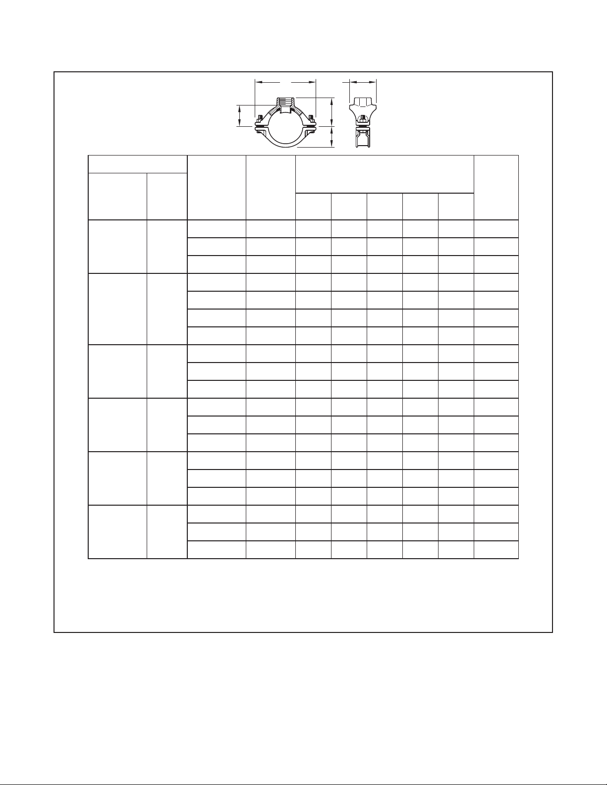
Sizes
• Run Sizes
1 in., 1-1/4 in., 1-1/2 in., 2 in.,
2-1/2 in., 76,1 mm (DN25, DN32,
DN40,DN50, DN65)
• Outlet Sizes
NPT or ISO 7-1 Pipe Threaded
3/8 in., 1/2 in., 3/4 in., 1 in.
(DN10, DN15, DN20, DN25)
Housing Materials
Ductile Iron conforming to
ASTM A 536, Grade 65-45-12
Finish
• Zinc electroplate conforming to
ASTM B 633 Type III
• Red (RAL3000) painted nish for
ISO Thread only
• Orange painted nish for
NPT Thread only
Bolts
Conforming to DIN 933,
M8 x 30 mm Class 8.8
Nuts
Flange nuts conforming to DIN 934, Class
8
Gasket
Grade “E” EPDM, Green color code
-30°F to 230°F (-34°C to 110°C)
See Data Sheet TFP1865 for additional
gasket information.
Friction Loss
Equivalent length of 1 in. Schedule 40 pipe
is 15 ft (4,6 m).
Hazen Williams coefficient = 120
For re protection pressure rating,
listing and approval information, contact
your GRINNELL representative.