nVent.com
|
1RAYCHEM-DG-H58489-XLTraceFireSprinkler-EN-1904
This step-by-step design guide provides the tools necessary to design a
RAYCHEM XL-Trace fire sprinkler freeze protection system. For other
applications or for design assistance, contact your nVent representative or call
(-. Also, visit our web site at nVent.com.
CONTENTS
INTRODUCTION...................................................................................... 1
How to Use this Guide........................................................................................................... 2
Safety Guidelines.................................................................................................................... 2
Warranty................................................................................................................................... 2
SYSTEM OVERVIEW ............................................................................... 3
Approvals ................................................................................................................................. 3
Self-Regulating Heating Cable Construction.................................................................... 4
FIRE SUPPRESSION SYSTEM FREEZE PROTECTION APPLICATIONS ... 5
Typical Pipe Freeze Protection System ............................................................................. 5
Fire Supply Lines .................................................................................................................... 6
Sprinkler Standpipes ............................................................................................................. 8
Branch Lines with Sprinklers ............................................................................................... 9
Freezer Application.............................................................................................................. 10
FIRE SUPPRESSION SYSTEM FREEZE PROTECTION DESIGN.............. 11
Design Step by Step............................................................................................................. 11
Step 1 Determine design conditions and pipe heat loss...................................... 12
Step 2 Select the heating cable................................................................................. 17
Step 3 Determine the heating cable length............................................................. 19
Step 4 Determine the electrical parameters...........................................................21
Step 5Select the connection kits and accessories ..............................................24
Step 6Select the control system ..............................................................................29
Step 7Complete the Bill of Materials..............................................................................30
INSTALLATION AND MAINTENANCE ................................................... 31
XL-TRACE SYSTEM FIRE SPRINKLER SYSTEM FREEZE
PROTECTION DESIGN WORKSHEET.....................................................32
INTRODUCTION
This design guide presents nVent recommendations for designing an XL-Trace
pipe freeze protection system for fire sprinkler piping. It provides design and
performance data, control options, electrical sizing information, and application
configuration suggestions. This guide does not give information on how to design
your fire protection system.
This guide does not cover applications in which any of the following conditions exist:
• Hazardous locations, as defined in national electrical codes
• Supply voltage other than V or – V
If your application conditions are different, or if you have any questions,
-.
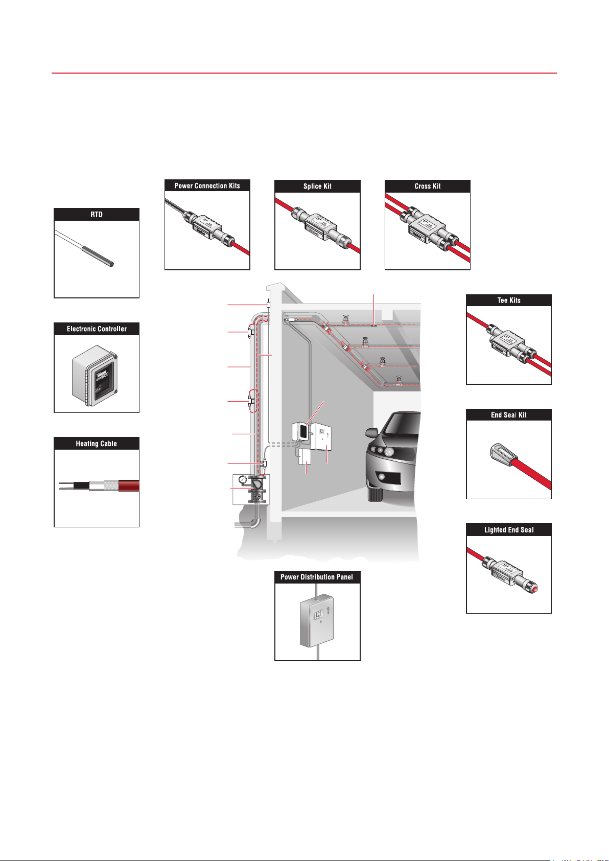
FIRE SPRINKLER SYSTEM FREEZE
PROTECTION — XL-TRACE SYSTEM