Grip G-SHW Series User instructions

G-SHW
Assembly and Operating Manual
Dear customer,
Congratulations!
You have chosen the best product we know how to make with our
30 years of experience and passion for precision.
Please follow the instructions in this manual to
avoid mistakes and save time.
In case you need further information or you have
further requests we will be glad to be at your disposal.
With best regards,
Your GRIP GmbH
GRIP GmbH Handhabungstechnik
44379 Dortmund, Germany Tel. +49 231 96450 01 www.grip-gmbh.com
SHW Connector
Rev. 1.04 1
4
6
4
7.1 Disassembly
4
5
5
Exploded view
EC-Declaration of incorporation
7
6
7
Warranty
7.2 Torque specifications
Parts list
Scope of delivery
3
Technical data
3
3
3
Contents
Operation
Safety
2.1 Symbol
2.2 Intended use
2.4 Safety indication
2.3 Environmental and operating conditions
Page
2
2
2
2
9
1
2
10
2
8.1 Spare and wear parts
Assembly
Maintenance and care
2
3
4
5
8

G-SHW
Assembly and Operating Manual
1 Operation
2 Safety
2.1 Symbol
2.2 Intended purpose
2.3 Environmental and operating conditions
2.4 Safety indication
Dangers may arise from the unit, if:
•
the product is not installed or inserted properly,
•the system is not used for its intended purpose,
•the safety and installation notes are not observed.
CAUTION! Never operate the hand lever when the load is suspended!
Rev. 1.04 2
NOTICE!
The unit may only be operated if the machine in which the unit is installed complies with the
relevant provisions of the machinery directive 2006-42-EC.
This symbol indicates possible hazards to persons or the SHW
Connector.
Everyone who is responsible for assembly, commissioning and maintenance must read and
understand the complete operating instructions. Improper use, which affects the function und
operational safety of the SHW Connector, is prohibited.
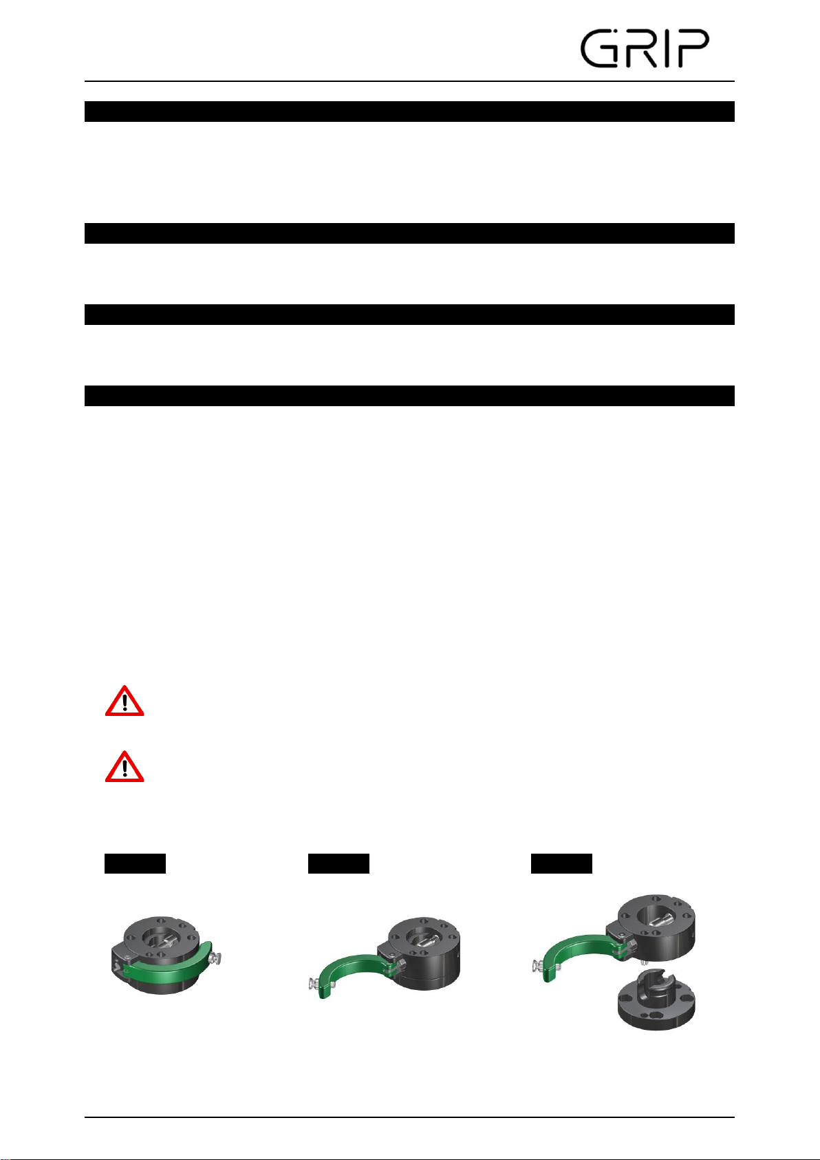
To open the change system, pull the locking pin on the hand lever. As a result, the crossway bolt
is displaced radially and releases the force-locked crimp connection in the bore of the lower
assembly. The upper and lower assembly can now be pulled apart.
Use this unit only in dry and splash-proof environments at room temperature as well as within the
application parameters defined in the technical specifications. If this is not the case, warranty
cannot be accepted. Exceptions are units designed especially for the respective conditions.
In order to prevent damage to the connector as well as injuries to the operator, the
lower assembly or the tool must be secured by hand or other devices before opening
the change system. Otherwise there is a risk that irreparable damages to the tool or
injury to the operator are caused by the unit falling down.
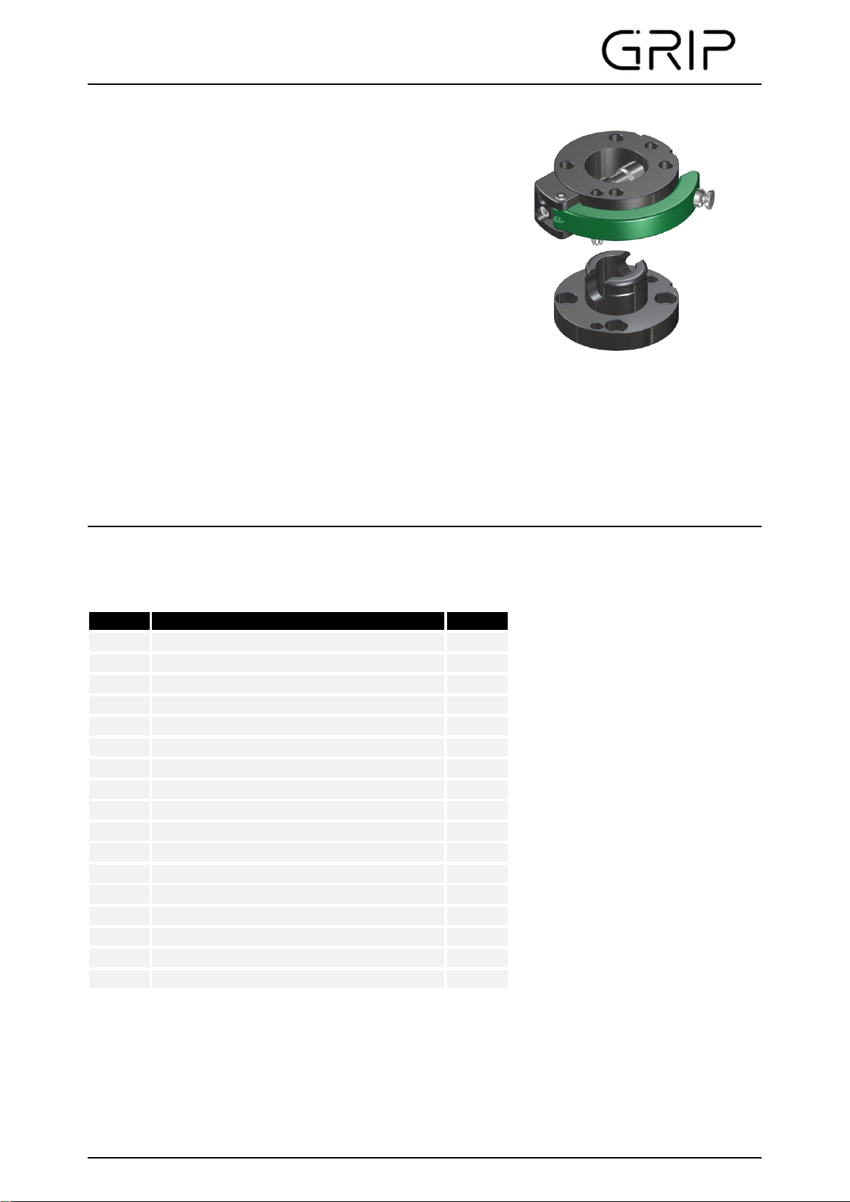
The SHW Connector has been designed as an interface between handling device and tool (e.g. gripper).
Furthermore, the SHW can also be used in special solutions, automation and also as a general
mechanical standard interface. The unit may only be used in the context of its technical specifications.
The system is intended for the installation in a machine. The requirements of the applicable instructions
must be considered and adhered to.

G-SHW
Assembly and Operating Manual
3 Warranty
4 Scope of Delivery
•SHW as shown in Image 7 depending on the order number of the upper or lower assembly.
5 Technical Data
6 Assembly
Rev. 1.04 3
Image 1
Image 2
Image 3
CAUTION!
Perform assembly work only when the power supply is switched off!
CAUTION! Risk of pinching the fingers when closing the SHW
When closing the connector ensure fingers are not between the upper and
lower assembly.
For axial adjustment all sizes provide a fitting bore. This bore is designed according to ISO 9409.
Optionally, the SHW can be provided with a SEK energy feed-through. The SEK enables the
simultaneous coupling of electrical lines. The SEK is mounted with two cylinder screws to the upper and
lower assemblies. For further installation instructions, please refer to the assembly and operating
instructions of the SEK.
Behold technical data sheets: TD-SHW050-EN, TD-SHW063-EN, TD-SHW080-EN, TD-SHW100-
EN, TD-SHW125-EN, TD-SHW160-EN
If the product is used as intended in 1-shift operation the warranty is valid for 24 months from the ex-
works delivery date under observance the mandatory maintenance and lubrication intervals and the given
operating conditions. Generally parts touching the work piece and wear parts are not part of the warranty.
Wear parts are listed in chapter 8.1. The unit is considered to be defective if its basic function "Lock" is no
longer functioning.
The upper assembly of the SHW Connector is mounted on the robot flange, the manipulator or
similar actuators. It can be centered with the help of a centering disc. The angular orientation is
determined by means of a fitting bore. The lower assembly is mounted on grippers, measuring
instruments or other tools. If the SHW Connector can not be installed directly, adapter flanges
must be used. Use screws according to DIN 912 or ISO 4762. The screw-in depth of the screws
must be observed. We recommend the use of a "medium-tight" screw lock.

G-SHW
Assembly and Operating Manual
Centering disc
7 Maintenance and care
7.1 Disassembly of the SHW
(Behold Image 6)
1. Disassemble the SHW.
2. If applicable shut off and remove compressed air lines.
3. Loosen the cylinder bolts for the holder (pos. 4).
4.
5.
6. Clean all parts thoroughly. Inspect for wear and defects.
7. Lubricate all fitting surfaces.
For assembly, reverse the order.
7.2 Torque specifications
M6 – 8,5 Nm; M8 – 20,6 Nm; M10 – 41 Nm; M12 – 71 Nm
Rev. 1.04 4
Remove the assembly holder (pos. 4) with components (pos. 2, 3, 5, 6, 9 and 10),
loosen the guide screws (pos 7 and 11).
To disassemble crossway bolt (pos. 2) from the other components (pos. 3, 5 and 6),
remove cylinder pins (pos. 9 and 10).
In order to archieve a precise fit, centering discs in every size are offered (as shown in image 3).
The use of a centering disc ensures that the upper assembly and/or lower assembly of the
Connector are properly centered. Installation on both the upper assembly and lower assembly is
possible (as shown in image 4).
Image 4
Image 5
The SHW is virtually maintenance-free. Check the semi-cylindrical bolt in regular intervals for
correct function. Keep the mating surface and the moving parts clean and lubricate them
slightly.
Spare parts and component parts of the SHW can be found on our homepage:

G-SHW
Assembly and Operating Manual
8 Parts list
8.1 Spare and wear parts, depending on size
Rev. 1.04 5
Description
Upper assembly
Crossway bolt
Hand lever
Holder
Cylinder bolt BL
Cylinder bolt QB
Strap pin
Quantity
1
1
1
1
1
2
Crossway bolt
Order-No.
EG-SHW…-QB
Lower assembly
12
Description
Pos.
1
1
2
6
7
Spring locking pin
3
Guiding screw
4
5
2
Pos.
8
9
10
11
Index pin
Hand lever
3
EG-SHW…-HH
Shim ring
1
1
1
2
1

G-SHW
Assembly and Operating Manual
9 Exploded view
Rev. 1.04 6
Image 6
Image 7
Upper assembly
Lower assembly

G-SHW
Assembly and Operating Manual
10 EC - Declaration of incorporation
according to the Machinery Directive 2006/42/EC, annex II B
The producer / distributor GRIP GmbH Handhabungstechnik
Alter Hellweg 70
D-44379 Dortmund, Germany
hereby declares that the following products
Product designation: Thrust lever change system (SHW)
Functional description:
Type designation: G-SHW050, 063, 080, 100, 125, 160
EN ISO 12100-1:2003
EN ISO 12100-2:2003
Authorized representative: Dipl.-Ing. (FH) Hasan Canti
Location: Dortmund
Date:
Dipl.-Ing. (FH) Hasan Canti
Executive Director
Rev. 1.04 7
Systems for the manual and form-closed exchange of components
such as grippers and tools on robots or receptacles
The provisions of the above-mentioned directives -including their effective amendments- comply
with the time of the declaration.
He further states that the following essential requirements of the Machinery Directive 2006/42/EC
were applied and observed:
annex I, numerics: 1.1.2; 1.1.3; 1.1.5; 1.3.2; 1.7.4
24.01.2023
He further states that the specific technical documentation has been drawn up in accordance with
annex VII, Part B.
The following harmonized standard has been applied:
Safety of Machinery- Basic concepts, general
principles for design- Part 2:
Technical principles (ISO 12100-2:2003)
Safety of Machinery- Basic concepts, general
principles for design- Part 1:
Basic terminology and methodology (ISO 12100-1:2003)
In the case of reasoned requests, the specific documents shall be sent to the national authorities
as follows: Post
The product mentioned above may only be put into operation if it has been established applicable
that the unit, into which the above-mentioned product is to be incorporated, complies with the
provisions of the Machinery Directive 2006/42 / EC.
This manual suits for next models
6
Table of contents