GRITAL GR5 User manual

MOTORIDUTTOREPERCANCELLI SCORREVOLI
ModeloGRITALGR5/220Volt

ENGLISH
5.4. Installazione del cremagliera
1) Posizionare il distanziale tre lettato sull’elemento
cremagliera, posizionandoli all’inizio dell cancello. In questo
modo, il gioco consentirà a qualsiasi slot di modiche da
apportare (Fig.8)
2) Portare manualmente il cancello in posizione di chiusura
3) Posizionare il primo pezzo di cremagliera a livello adeguato
sul pignone e saldare il distanziatore lettato sul cancello come
mostrato in Fig.9A
4) Muovere manualmente il cancello, vericando che la
cremagliera sia in appoggio sul pignone e saldare il distanziale
secondo e terzo.
5) Accertarsi che tra cremagliera e pignone c’è sempre ca. 1
millimetro clearance (vedi Fig. 10)
6) Portare altro elemento di cremagliera vicino al precedente,
con un pezzo di cremagliera come in Fig. 11 per sincronizzare i
denti delle due cremagliere.
7) Muovere manualmente il cancello e saldare i tre distanziali
lettati.
8) Procedere no alla copertura completa del cancello.
5.5. Installazione degli interruttori di ne corsa
1) Prendere il cancello nella sua posizione di chiusura, c’era il
necorsa sulla cremagliera
2) Segnare la posizione del foro sulla cremagliera. Praticare
dei fori e avvitare il necorsa sulla cremagliera con le viti in
dotazione.
3) Tirare l’anta in posizione di apertura, ripetere l’operazione.
4) Assicurarsi che il ante 1 - 3 cm, a seconda del peso del
cancello tra il portone e fermo meccanico. In questo modo
l’operatore si ferma senza far rumore e anche se si vuole fare
sblocco manuale è più facile.
5.6. ATTENZIONE
- Assicurarsi che durante la corsa del cancello, tutti gli
elementi della cremagliera correttamente ingranare con il
pignone.
- Non, in qualsiasi occasione, saldare gli elementi della
cremagliera nè al distanziatore o gli uni agli altri.
- Vericare manualmente che il cancello raggiunge
abitualmente i fermi meccanici di limite e gli zoppi sicuri che
non vi è alcun attrito durante la corsa del cancello.
- Non utilizzare grasso o altri prodotti lubricanti tra pignone
e cremagliera.
5,7. Funzionamento manuale
Per azionare manualmente il cancello utilizzare lo sblocco
come segue:
- Prendete la chiave e inserirla alla serratura.
- Girare la chiave in senso orario a 90 °
- Tirare e aprire lo sblocco manuale,
- Dopo aver aperto lo sblocco manuale, è possibile azionare
manualmente la porta.
- Per ripristinare il normale funzionamento, chiudere la leva
di sblocco manuale ed azionare il cancello manualmente
dolcemente no al danzamento. Quindi è possibile utilizzare
telecomandi e gestire l’automazione.
6.0. MANUTENZIONE
Eseguire i lavori di seguire almeno ogni 6 mesi.
- Controllare l’ecienza del sistema di sblocco
- Controllare l’ecienza dei dispositivi di sicurezza e accessori.
7,0. RIPARAZIONI
Per eventuali riparazioni, contattare i centri di riparazione
autorizzati
IMPORTANT NOTICE FOR THE INSTALLER
GENERAL SAFETY REGULATIONS
1) ATTENTION! To ensure the safety of the people, it is important
that you read the following instructions. Incorrect installation or
incorrect use of the product could cause serious harm to people.
2) Carefully read the instructions before beginning to install the
product.
3) This product was designed and built strictly for the use
indicated in this documentation. Any other use, not expressly
indicated here, could compromise the good condition and
operation of the product and be a source of danger.
4) Do not install the equipment in an explosive atmosphere: the
presence of inammable gas or fumes is a serious danger to safety.
5) The mechanical parts must conform to the provisions of
Standards EN12604 and EN12605. For non-EU countries, to obtain
an adequate level of safety, the Standards mentioned above must
be observed, in additional to legal regulations.
6) The installation must conrm the Standards EN12453 and
EN12445.
7) Before attempting any job on the system, cut the electrical
power.
8) The main power supply of the automated system must be
tted with an all-pole switch with contact opening distance of
3mm or greater. Use of 6A thermal breaker with all-pole circuit
break is recommended.
9) Make sure that the earthing system is perfectly constructed,
and connect metal parts of the means of the closure to it.
10) The safety devices ( EN 12978) protect any danger areas
against mechanical movement risk, such as crushing, dragging
and shearing.
11) Use at least one indicator-light is recommended for every
system, as well as warning sign adequately secured to the frame
structure.
12) We decline all liability caused by improper use or use other
than that for which the automated system was intended.
13) We decline all liability as concerns safety and ecient
operation of the automated system, if system components are not
produced by us.
14) For maintenance, strictly use original parts by us.
15) Do not in any way modify the components of the automated
system.
16) The installer shall supply all information concerning manual
operation of the system in case of an emergency, and shall hand
over to the user the warnings handbook supplied with the product.
17) Do not allow children or adults to stay near the product while
is operating.
18) Keep remote controls or other pulse generators away from
children, to prevent the automated system from being activated
involuntarily.
19) Transit is allowed only when the gate is fully open.
20) Do not leave packing materials within the reach of children
as such materials are potential sources of danger.
21) The user must not attempt any kind of repair or direct action
whatever and contact qualied personnel only.
1. DESCRIPTION
Automated system for residential sliding gates with leaves up
to 8 meter long and 500kg in weight. It consists of a reversing
electro-mechanical gearmotor, powered by 230Vac, transformer
through toroidal and power supply board.
The automated system houses a programmable electronic
control board that enables setting of function logics, work times
and pause times, gate speed, anti-crushing sensitivity as well as
partial opening width.
The reversing system guarantees the gate will automatically
lock when the motor is not operating. A release system enables
the gate to be moved by hand in case of malfunction.
1.1. Dimension ( mm )
Note :
1) To lay electric cables, use adequate rigid and/or exible tubes.
2) To avoid any kind of interference always separate low voltage
connection cables from 230Vac power cables.
3) The description of system is standard system, but we did not
provide all parts. If you want system accessories, please contact us
or your supplier.
22,5cm
11cm
6cm
13cm
32cm
18cm
22cm
3,5cm
3,7cm
13,7cm
9,5cm
28cm
8
10
11
9A
9B
2.1.Technical specifications
Technical specifications Data
Gate weight 500kg
Power supply 220-230 Vac
Rated absorbed power (watt) 250 watt
Current absorbed ( A ) 1.1 A
Capacitor ( ìF ) 10 μF
Thermal Protection 150o C
Working temperature -45o C + 65o C
Speed m/min 10 m / min
Max thrust ( N ) 390 Nm
Motor speed ( rpm ) 1400
Protection Level IP 55
Motion ( gear rack ) Gear rack module 4

5. Installing procedure
5.1. Preliminary checks
To ensure safety and eciently operating automated system,
make sure the following conditions are applied :
-The structure of the gate must be suitable for being
automated. Check if the gate is strong and rigid, and that its
dimensions and weight conform to those indicated in the
technical specications.
-Make sure that the gate slides well, easy and without any
inclicnation
-Make sure that the gate slides uniformly and correctly,
without any irregular friction during its entire travel
-Check if the upper guide and travel limit mechanical stops
are installed
Remove any locks and lock bolts. We advise you to have any
metalwork carried out before the automated system is installed
5.2.Positioning the foundation plate
-Put the foundation plate to the oor, using adequate
expansion plugs
-Use a level, check if the foundation plate is perfectly
horizontal.
5.3.Positioning the operator
-Lay the electric cables for the connection of the accessories
and power supply.To make connections easier, allow the cables
to project by the required length for connection to the control
board etc.
-Position the operator on the plate, using the supplied screws.
-Adjust the distance of the operator from the gate so the gate
slides without problem
-Fix the operator tightening the screws as shown in Fig7.
5.4.Installing the rack
1)Place the three threaded spacer on the rack element,
positioning them at the top of the slot. In these way, the slot
play will enable any adjustment to be made ( Fig. 8 )
2)Manually take the leaf into its closing position
3)Lay the rst piece of rack at appropriate level on the pinion
and weld the threaded spacer on the gate as shown in Fig 9A .
4)Move the gate manually, checking if the rack is resting on
the pinion, and weld the second and third spacer. Fig 9B
3.The packing list
Please check the operator packing before installing the
automated system.
4. Installation Tools
No Description Quant. No Description Quant.
1 Motor 1 6 Expanded screw 4
2 Left limit 1 7 Screw 4
3 Right limit 1 8 Release key 2
4 M6 Screw 4 9 Manual 1
5 Foundation plate 1 10 Remote control 2
5)Make sure that between rack and the pinion there is always
approx. 1mm clearance ( see Fig. 10)
6)Bring another rack element near to the previous one, using
a piece of rack as shpwn in Fig.11 to synchronise the teeth of
the two racks.
7)Move the gate manually and weld the three threaded
spacers.
8)Proceed until the gate is fully covered.
5.5.Installing the limit switches
1)Take the leaf into its closing position, lay the limit-switch
on the rack
2)Mark the hole position on the rack. Drill holes and screw the
limit-switch on the rack with the supplied screws.
3)Pull the leaf into the opening position, repeat the operation.
4)Make sure that the gate leaves 1 - 3 cm, depending on gate
weight, between gate and mechanical stop. In these way the
operator stops without making noise and also if you want to
make manual release it is easier.
5.6.ATTENTION
-Make sure that during the gate travel, all the rack elements
mesh correctly with the pinion.
-Do not, on any occasion, weld the rack elements either to the
spacer or to each other.
-Manually check if the gate habitually reaches the travel limit
mechanical stops and lame sure that there is no friction during
gate travel.
-Do not use grease or other lubricants between rack and
pinion.
5.7.Manual operation
To operate the gate manually use the release as follows :
-Take the key and insert it to the lock.
-Turn the key clockwise 90o
-Pull and open the manual release.
-After opened the manual release, you can operate the door
manually.
-To reset the standard operation running, close the manual
release lever and operate the gate manually softly until
engagement. Then you can use you remote controls and
operate the automation.
6.0. MAINTENANCE
Carry out the follow jobs at least every 6 months.
-Check the eciency of the release system
-Check the eciency of the safety devices and accessories.
7.0. REPAIRS
For any repairs, contact only authorised repair centres and
technicians.
5
6
7
8
10
11
9A
9B

ΣΗΜΑΝΤΙΚΗ ΣΗΜΕΙΩΣΗ ΓΙΑ ΤΟΝ ΕΓΚΑΤΑΣΤΑΤΗ
ΓΕΝΙΚΟΙ ΚΑΝΟΝΙΣΜΟΙ ΑΣΦΑΛΕΙΑΣ
1) ΠΡΟΣΟΧΗ! Για να εξασφαλιστεί η ασφάλεια των ανθρώπων,
είναι σημαντικό να διαβάσετε τις παρακάτω οδηγίες. Λανθασμένη
εγκατάσταση ή λανθασμένη χρήση του προϊόντος θα μπορούσε να
προκαλέσει σοβαρή βλάβη σε ανθρώπους.
2) Διαβάστε προσεκτικά τις οδηγίες πριν ξεκινήσετε την
εγκατάσταση του προϊόντος.
3) Το προϊόν αυτό έχει σχεδιαστεί και κατασκευαστεί
αποκλειστικά για χρήση που αναφέρεται σε αυτήν την τεκμηρίωση.
Οποιαδήποτε άλλη χρήση, όχι ρητά αναφέρεται εδώ, θα μπορούσε
να θέσει σε κίνδυνο την καλή κατάσταση και λειτουργία του
προϊόντος και να είναι μια πηγή κινδύνου.
4) Μην τοποθετείτε τη συσκευή σε μια εκρηκτική ατμόσφαιρα: η
παρουσία εύφλεκτων αερίων ή καπνών αποτελεί σοβαρό κίνδυνο
για την ασφάλεια.
5) Τα μηχανικά μέρη πρέπει να συμμορφώνονται με τις διατάξεις
των προτύπων EN12604 και EN12605. Για χώρες εκτός ΕΕ, να
αποκτήσουν ένα επαρκές επίπεδο ασφάλειας, τα πρότυπα που
αναφέρονται πιο πάνω πρέπει να τηρούνται, σε επιπλέον νομικές
διατάξεις.
6) Η εγκατάσταση πρέπει να πληρούν τα πρότυπα EN12453 και
EN12445.
7) Πριν επιχειρήσετε οποιαδήποτε εργασία σχετικά με το
σύστημα, κόψτε το ηλεκτρικό ρεύμα.
8) Η κύρια πηγή τροφοδοσίας του αυτοματοποιημένου
συστήματος πρέπει να είναι εφοδιασμένο με διακόπτη όλων των
πόλων με επαφή άνοιγμα απόσταση από 3mm ή μεγαλύτερη. Η
χρήση του 6Α θερμική διακόπτη με όλα τα ρεύματα διάλειμμα
κύκλωμα συνιστάται.
9) Βεβαιωθείτε ότι το σύστημα γείωσης είναι άψογα
κατασκευασμένο και συνδέστε τα μεταλλικά μέρη από τα μέσα του
κλεισίματος σε αυτό.
10) Οι διατάξεις ασφαλείας (EN 12978) προστατεύουν τις
περιοχές που κινδυνεύουν από τη μηχανική κίνηση , όπως η
σύνθλιψη, το σύρσιμο κτλ.
11) Η χρήση τουλάχιστον μία από τις ενδείξεις-φως συνιστάται
για κάθε σύστημα, καθώς και προειδοποιητικό σημάδι επαρκώς
στερεωμένο στη δομή του πλαισίου.
12) Δεν φέρουμε καμία ευθύνη για οτιδήποτε που προκαλείται
από ακατάλληλη χρήση ή χρήση άλλη από εκείνη για την οποία το
αυτοματοποιημένο σύστημα προορίζετε.
13) ) Δεν φέρουμε καμία ευθύνη όσον αφορά την ασφάλεια
και την αποτελεσματική λειτουργία του αυτοματοποιημένου
συστήματος, αν όλα τα εξαρτήματα του συστήματος δεν είναι
εγκεκριμένα από εμάς.
14) Για τη συντήρηση, θα πρέπει να χρησιμοποιείται
αποκλειστικά γνήσια ανταλλακτικά από εμάς.
15) Μην επιχειρήσετε με οποιοδήποτε τρόπο να τροποποιήσει τα
στοιχεία του αυτοματοποιημένου συστήματος.
16) Ο εγκατάστασης θα πρέπει να παρέχει όλες τις πληροφορίες
σχετικά με το εγχειρίδιο λειτουργίας του συστήματος σε περίπτωση
έκτακτης ανάγκης, και να παραδώσει στο τελικό χρήστη το
εγχειρίδιο προειδοποιήσεις που παρέχονται με το προϊόν.
17) Μην επιτρέπετε σε παιδιά ή ενήλικες να είναι κοντά στην
πόρτα , ενώ βρίσκεται σε λειτουργία.
18) Κρατήστε τα τηλεχειριστήρια ή άλλες γεννήτριες παλμών
μακριά από τα παιδιά, για την πρόληψη το αυτοματοποιημένο
σύστημα από το να ενεργοποιηθεί ακούσια.
19) Διαμετακόμιση επιτρέπεται μόνο όταν η πύλη είναι πλήρως
ανοικτή.
20) Μην αφήνετε τα υλικά συσκευασίας κοντά στα παιδιά, επειδή
τα υλικά αυτά είναι πιθανές πηγές κινδύνου.
21) Για την συντήρηση η την επισκευή της συσκευής
απευθυνθείτε μονό σε ειδικευμένο τεχνικό.
Περιγραφή
Αυτοματοποιημένο σύστημα μοτέρ για οικιακές η ελαφρός
βιομηχανικές συρόμενες πόρτες με φύλλα έως 8 μέτρα μήκος
και 500kg βάρος. Αποτελείται από ένα μη αντιστρεπτό
ηλεκτρομηχανικό μειωτήρα, που τροφοδοτείται από 230Vac
μέσω μετασχηματιστή και ηλεκτρονικής πλακέτας αυτοματισμό.
Το αυτοματοποιημένο σύστημα φέρει ενσωματωμένοι
ηλεκτρονική πλακέτα Seav model LRS2102R++ , που
επιτρέπει τον προγραμματισμό των λειτουργιών όπως χρόνο
κινητήρα, αυτόματο χρόνο κλεισίματος, ταχύτητα & δύναμη
μοτέρ, ευαισθησία αντί-σύνθλιψης καθώς και μερικό πλάτος
ανοίγματος.
Η πόρτα κλειδώνει αυτόματα όταν το μοτέρ δεν λειτουργεί.
Ένα σύστημα απελευθέρωσης επιτρέπει στην πόρτα την
χειροκίνητη λειτουργιά της σε περίπτωση δυσλειτουργίας η
έκτακτης ανάγκης.
Το αυτοματοποιημένο σύστημα σχεδιαστικέ και
κατασκευάστηκε για τον έλεγχο της πρόσβασης οχημάτων. Μη
χρησιμοποιείτε για κανένα άλλο σκοπό.
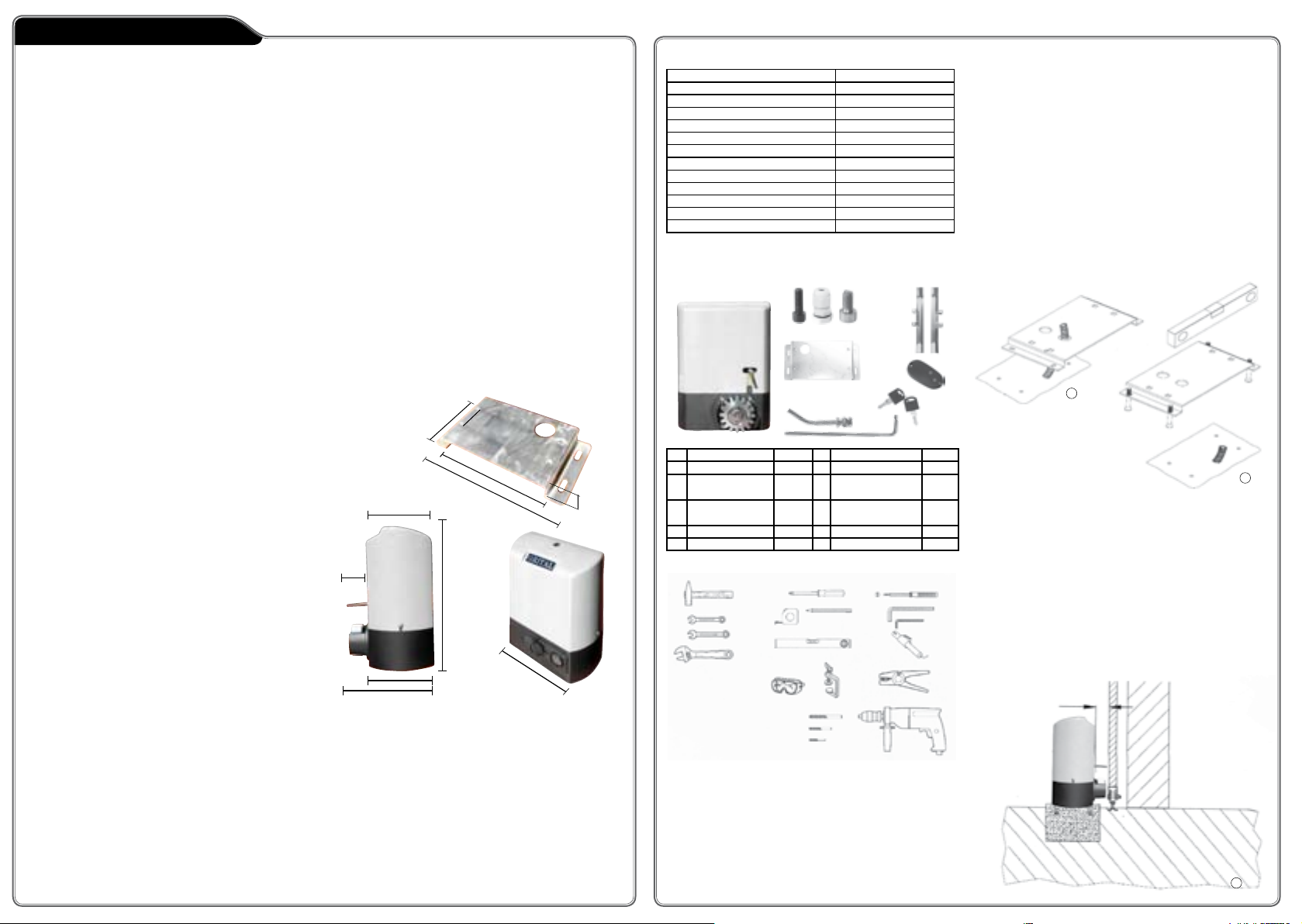
1.1. Διαστάσεις
3. Συσκευασία
Παρακαλούμε ελέγξτε τα περιεχόμενα πριν από την
εγκατάσταση του συστήματος.
4. Εργαλεία εγκατάστασης
No Περιγραφή Ποσοτ. No Περιγραφή Ποσοτ.
1 Μοτέρ 1 6 Βύσματα στήριξης 4
2 Αριστερό
τερματικό
1 7 Βίδες στήριξης 4
3 Δεξί τερματικό 1 8 Κλειδιά
απασφαλισης
2
4 Βίδες Μ6 4 9 Οδηγίες χρήσης 1
5 Βάση στήριξης 1 10 Τηλεχειριστήρια 2
5.3. Τοποθέτηση του μοτέρ
- Περάστε τα καλώδια για την σύνδεση των αξεσουάρ και την
παροχή του ηλεκτρικού ρεύματος όπως φαίνεται στο σχήμα.
Για μια πιο εύκολη σύνδεση αφήστε τα καλώδια σε μεγαλύτερο
μήκος.
- Στηρίξτε το μοτέρ στη βάση με τις 4 βίδες
- Ρυθμίστε την απόσταση του μοτέρ από την πόρτα
ελέγχοντας ώστε η πόρτα να κινείτε ομαλά και να μην μαγκώνει
πουθενά.
- Πολύ σημαντικό είναι να ελέγξετε να μην κολλάει πουθενά το
τερματικό ελατήριο.
11cm
22cm
3,5cm
3,7cm
13,7cm
9,5cm
28cm
6cm
13cm
32cm
22,5cm
18cm
ΕΛΛΗΝΙΚΑ
5
6
7
2.1 Τεχνικά χαρακτηριστικά
Τεχνικά χαρακτηριστικά
Βάρος πόρτας 500kg
Παροχή 220-230 Vac
Απορροφημένη ισχύς 250 watt
Ένταση ρεύματος 1.1 A
Πυκνωτής ( μF ) 10 μF
Θερμική προστασία 150o C
Θερμοκρασίες λειτουργίας -45o C + 65o C
Ταχύτητα θύρας m/min 10 m / min
Αρχική Ώθηση ( N ) 390Νm
Ταχύτητα μοτέρ ( rpm ) 1400
Βαθμός προστασίας IP IP 55
Κίνηση ( gear rack ) Κρεμμαγιερα module 4
5. Διαδικασία εγκατάστασης
5.1. Προκαταρτικοί έλεγχοι
Για να εξασφαλιστεί ηασφάλεια και ηαποτελεσματική
λειτουργία του συστήματος, βεβαιωθείτε ότι ισχύουν οι
ακόλουθες προϋποθέσεις :
- Η δομή της πόρτας θα πρέπει να είναι κατάλληλη για να
αυτοματοποιηθεί. Ελέγξτε αν η πόρτα είναι ισχυρή και άκαμπτη,
και ότι οι διαστάσεις και το βάρος της είναι σύμφωνες με αυτές
που αναφέρονται στις τεχνικές προδιαγραφές.
- Βεβαιωθείτε ότι η πόρτα κινείται ομαλά, εύκολα, χωρίς
τριβές και χωρίς κλήση.
- Βεβαιωθείτε ότι έχουν τοποθετηθεί οι κατάλληλες
στηρίξεις της πόρτας και ότι έχουν τοποθετηθεί μηχανικά stop
ορίων διαδρομής.
- Αφαιρέστε τυχόν κλειδαριές και σύρτες κλειδώματος. Σας
συμβουλεύουμε, όποιες σιδηρικές εργασίες της πόρτας να
πραγματοποιηθούν πριν την εγκατάσταση του
αυτοματοποιημένου συστήματος.
5.2.Τοποθέτηση της βάσης στήριξης
-Βάλτε τη βάση στήριξης στο πάτωμα,περάστε τα καλώδια
από τη διατομή της βάσης και στηρίξτε με τα κατάλληλα
βύσματα διαστολής.
- Είναι σημαντικό η βάση στήριξης να τοποθετηθεί και να
στηριχθεί σωστά
(βλέπε σχήμα 5 και 6)
-Χρησιμοποιήστε αλφάδι για να τοποθετηθεί ηβάση
απολύτως οριζόντια.
Σημειώσεις:
1)Για να περάσετε τα καλώδια χρησιμοποιήστε εύκαμπτο
σωλήνα .
2)Για να αποφύγετε κάθε είδους παρεμβολές συνίσταται να
ξεχωρίζεται πάντα τα καλώδια σύνδεσης χαμηλής τάσης από τα
καλώδια τροφοδοσίας 230Vac.
3)Η περιγραφή του συστήματος είναι ενός standard
συστήματος. Στην συσκευασία δεν παρέχονται
όλα τα αξεσουάρ. Για τα πρόσθετα αξεσουάρ συστήματος,
παρακαλούμε επικοινωνήστε μαζί μας η με εξουσιοδοτημένο
αντιπρόσωπο της GRITAL.

6.0. ΣΥΝΤΗΡΗΣΗ
Πραγματοποιήστε τουλάχιστον κάθε 6 μήνες τους παρακάτω
ελέγχους.
- Έλεγχος της αποτελεσματικότητας του συστήματος
απελευθέρωσης
- Έλεγχος της αποτελεσματικότητας των συστημάτων
ασφαλείας και των αξεσουάρ.
7.0. ΕΠΙΣΚΕΥΕΣ
Για οποιαδήποτε επισκευή, επικοινωνήστε μόνο
εξουσιοδοτημένα κέντρα επισκευής και τεχνικούς.
LISTA PARTI DI RICAMBIO / SPARE PARTS / ΑΝΤΑΛΛΑΚΤΙΚΑ
Description of the system
1. Drive unit
2. Control panel
3. Left limit
4. Right limit
5. Rack
6. Key operated selector switch
7. Safety photecells
8. Antenna
9. Pulsar ashing light
8
10
11
9A
9B
1
5
2
7
6
8
4
9
3
10
Denominazione Description Περιγραφή
1Carter Cover Καπάκι
2Carter motore Motor base Βάση μοτέρ
3Motore Statore Motor stator Περιέλιξη μοτέρ
4Motore rotore Motor rotor Ρότορας Μοτέρ
5Leva di sblocco Release lever Χερούλι απασφάλισης
6Albero uscita Output shaft Σύστημα μετάδοσης
7Ingranaggio Gear Εξωτερικό γρανάζι
8Finecorsa Limit switch Τερματοδιακόπτης
9Condesattore Capacitor Πυκνωτής
10 Centralina Control panel Ηλεκτρονική πλακέτα
modelGRITAL, GR5 / 220volt
5.4. Εγκατάσταση κρεμαγιέρας
-Τοποθετήστε τους 3αποστάτες στην κρεμαγιέρα με το
κεφάλι τους προς την κορυφή, βλέπε εικόνα.
- Απελευθερώστε το μοτέρ και μεταφέρεται την πόρτα στην
θέση κλεισίματος.
- Τοποθετήστε το πρώτο κομμάτι της κρεμαγιέρας πάνω στο
γρανάζι του μοτέρ και συγκολλήστε με ηλεκτροκολλητή.
- Βεβαιωθείτε ότι μεταξύ της κρεμαγιέρας και του γραναζιού
του μοτέρ υπάρχει πάντα περίπου 1 χιλ. αέρας.
- Φερτέ ένα άλλο κομμάτι κρεμαγιέρα κοντά στο πρώτο,
χρησιμοποιώντας ένα κομμάτι από κάτω για να συγχρονίσετε τα
δόντια από τις δυο κρεμαγιέρες. Βλέπε σχήμα
- Μετακινήστε την πόρτα με το χέρι και συγκολλήστε τους
αποστάτες έναν προς έναν.
- Συνεχίστε μέχρι να καλύψετε όλο το μήκος της πόρτας.
5.5. Εγκατάσταση τερματικών διακοπτών
-Φέρτε το φύλλο στη θέση κλεισίματος και ορίστε τη θέση
του τερματικού πάνω στην κρεμαγιέρα.
- Βιδώστε το τερματικό στην κρεμαγιέρα
- Επαναλάβετε τη διαδικασία για τη θέση ανοίγματος.
- Βεβαιωθείτε ότι η πόρτα αφήνει 1 – 3 cm αέρα, ανάλογα με
το βάρος της πόρτας, μεταξύ πόρτας & μηχανικών τερματικών
stop. Με αυτόν τον τρόπο αφενός μεν η πόρτα θα σταματήσει
χωρίς να κάνει θόρυβο άλλα το πιο σημαντικό, θα είναι
ευκόλοτερη η χειροκίνητη απελευθέρωση.
5.6. ΠΡΟΣΟΧΗ
- Βεβαιωθείτε ότι ηκρεμαγιέρα έχει συγκολληθεί σωστά
και ότι είναι σε επαφή με το γρανάζι σε όλη την κίνηση της
πόρτας.
- Μην κολλάτε τους αποστάτες με την κρεμαγιέρα.
- Μη χρησιμοποιείτε γράσο ή άλλα λιπαντικά ανάμεσα στην
κρεμαγιέρα και στο γρανάζι.
5.7. Χειροκίνητη λειτουργία
Για να λειτουργήσει ηπόρτα χειροκίνητα χρησιμοποιείστε το
μοχλό απελευθέρωσης ως εξής:
- Πάρτε το κλειδί και τοποθετήστε το στην κλειδαριά.
- Γυρίστε το κλειδί δεξιόστροφα 90ο
- Τραβήξτε και ανοίξτε το μοχλό απελευθέρωσης.
- Αφού ανοίξετε το μοχλό απελευθέρωσης, μπορείτε να
χειρίζεστε την πόρτα χειροκίνητα.
- Για να επαναφέρετε την τυπική λειτουργία του μοτέρ, κλείστε
το χειροκίνητο μοχλό απελευθέρωσης και λειτουργείστε την
πόρτα με το χέρι απαλά, μέχρι την εμπλοκή. Στη συνέχεια,
μπορείτε να χρησιμοποιήσετε τα τηλεχειριστήρια για τη
λειτουργία του αυτοματισμού.

manual Grital 5 vers01.12
DichiarazionediconformitàCE
L’operatoreper cancelli scorrevoli modelo GRITALGR5/
220Volt
a a ca a acca aba c a acca c a
macchina considerata dalla direttiva 89/382 CEE, come modificata
a c a
c a a CE:
Direttiva, Bassa Tensione 73/23/CEE e 96/38/CEE successiva modifica
Direttiva, compatibilita elettromagnetica 89/336/CE
E che:
a aca:
EN 60335-2-103:2003, EN62233: 2008, EN 60335-1:2002, EN61000-6-3: 2007,
EN61000-3-2: 2006, EN61000-3-3: 2008, EN61000-6-1: 2007.
e dichiara inoltre che è vietato mettere la macchina in servizio finché la macchina in cui sarà incorporato o di cui
diverrà componente sia stata identificata e dichiarata conforme alle condizioni della Direttiva 98/37/CE.
Declarationof Conformity CE
Theoperator forsliding gatesmodel GRITAL5/ 220Volt
I b c ac b abw ac c ac
covered by Directive 89/382 EEC, as amended
D c cw c
D cw w EEc Dc :
Direttiva bassa tensione 73/23/CEE and subsequent amendment 96/38/CEE
Direttiva compatibilita elettromagnetica 89/336/CE
And that :
w aa a b a :
EN 60335-2-103:2003, EN62233:2008, EN 60335-1:2002, EN61000-6-3:2007,
EN61000-3-2:2006, EN61000-3-3:2008, EN61000-6-1:2007.
and furthermore declares that it is prohibited to put the machinery into service until the machinery in which it will be
integrated or of which it will become a component has been identified and declared as conforming to the conditions of
Directive 98/37/EC.
Δήλωση Συμμόρφωσης CE
Μοτέρ για συρόμενες πόρτες μοντέλο GRITALGR5/ 220Volt
προορίζεται να ενσωματωθεί σε μηχάνημα ήνα συναρμολογηθεί με άλλες μηχανές για να αποτελέσει μηχανήματα
που καλύπτονται από την οδηγία 89/382 ΕΟΚ, όπως τροποποιήθηκε
Επομένως από κάθε άποψη πληρούν τις διατάξεις της εν λόγωοδηγίας
Έχει συμμορφωθεί με τις διατάξεις των ακόλουθων οδηγιών ΕΚάλλων:
Direttiva Bassa Tensione 73/23/ΕΚ και την επακόλουθη τροποποίηση 96/38/CEE
Direttiva Compatibilità elettromagnetica 89/336/CE
Και ότι:
Τα παρακάτω πρότυπα έχουν εφαρμοστεί:
EN 60335-2-103:2003, EN62233: 2008, ΕΝ 60335-1:2002, EN61000-6-3: 2007,
EN61000-3-2: 2006, EN61000-3-3: 2008, EN61000-6-1: 2007.
και επιπλέον δηλώνει ότι απαγορεύεται η διάθεση του μηχανήματος σε λειτουργία μέχρι το μηχάνημα στο οποίο θα
ενσωματωθεί ή του οποίου θα γίνει ένα συστατικό έχει αναγνωριστεί και δηλώνονται ως σύμφωνα με τους όρους της
οδηγίας 98/37/ΕΚ.
Table of contents
Languages:
Other GRITAL Garage Door Opener manuals
Popular Garage Door Opener manuals by other brands

Cumberland
Cumberland FLX-5363 installation manual

EINHELL
EINHELL TAF 362 Mounting and operating instructions

MOX
MOX C40 Series Instruction and warnings for the installer

Automatic Technology
Automatic Technology SecuraLift Trio installation instructions

Chamberlain
Chamberlain LiftMaster Professional Security+ 3850 owner's manual

Autoglide
Autoglide CASA-M Series product manual