Grizzly G0761 User manual

MODEL G0761
HEAVY-DUTY BENCHTOP
MILL/DRILL w/POWER FEED
& TAPPING
OWNER'S MANUAL
(For models manufactured since 10/13)
COPYRIGHT © MAY, 2014 BY GRIZZLY INDUSTRIAL, INC.
WARNING: NO PORTION OF THIS MANUAL MAY BE REPRODUCED IN ANY SHAPE
OR FORM WITHOUT THE WRITTEN APPROVAL OF GRIZZLY INDUSTRIAL, INC.
#TS16056 PRINTED IN CHINA V1.05.14

This manual provides critical safety instructions on the proper setup,
operation, maintenance, and service of this machine/tool. Save this
document, refer to it often, and use it to instruct other operators.
Failure to read, understand and follow the instructions in this manual
may result in fire or serious personal injury—including amputation,
electrocution, or death.
The owner of this machine/tool is solely responsible for its safe use.
This responsibility includes but is not limited to proper installation in
a safe environment, personnel training and usage authorization,
proper inspection and maintenance, manual availability and compre-
hension, application of safety devices, cutting/sanding/grinding tool
integrity, and the usage of personal protective equipment.
The manufacturer will not be held liable for injury or property damage
from negligence, improper training, machine modifications or misuse.
Some dust created by power sanding, sawing, grinding, drilling, and
other construction activities contains chemicals known to the State
of California to cause cancer, birth defects or other reproductive
harm. Some examples of these chemicals are:
• Lead from lead-based paints.
• Crystalline silica from bricks, cement and other masonry products.
• Arsenic and chromium from chemically-treated lumber.
Your risk from these exposures varies, depending on how often you
do this type of work. To reduce your exposure to these chemicals:
Work in a well ventilated area, and work with approved safety equip-
ment, such as those dust masks that are specially designed to filter
out microscopic particles.

Table of Contents
INTRODUCTION............................................... 2
Machine Description ...................................... 2
Contact Info.................................................... 2
Manual Accuracy ........................................... 2
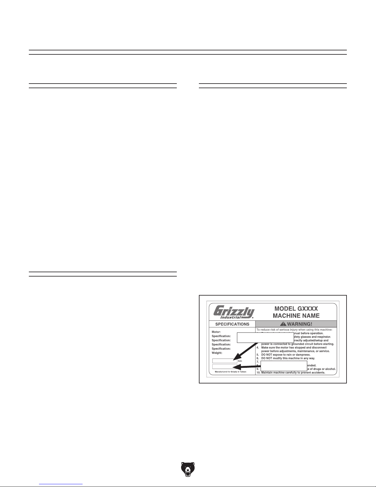
Identification ................................................... 3
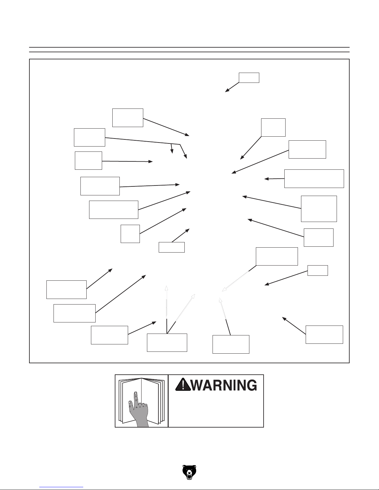
Basic Controls ................................................ 4
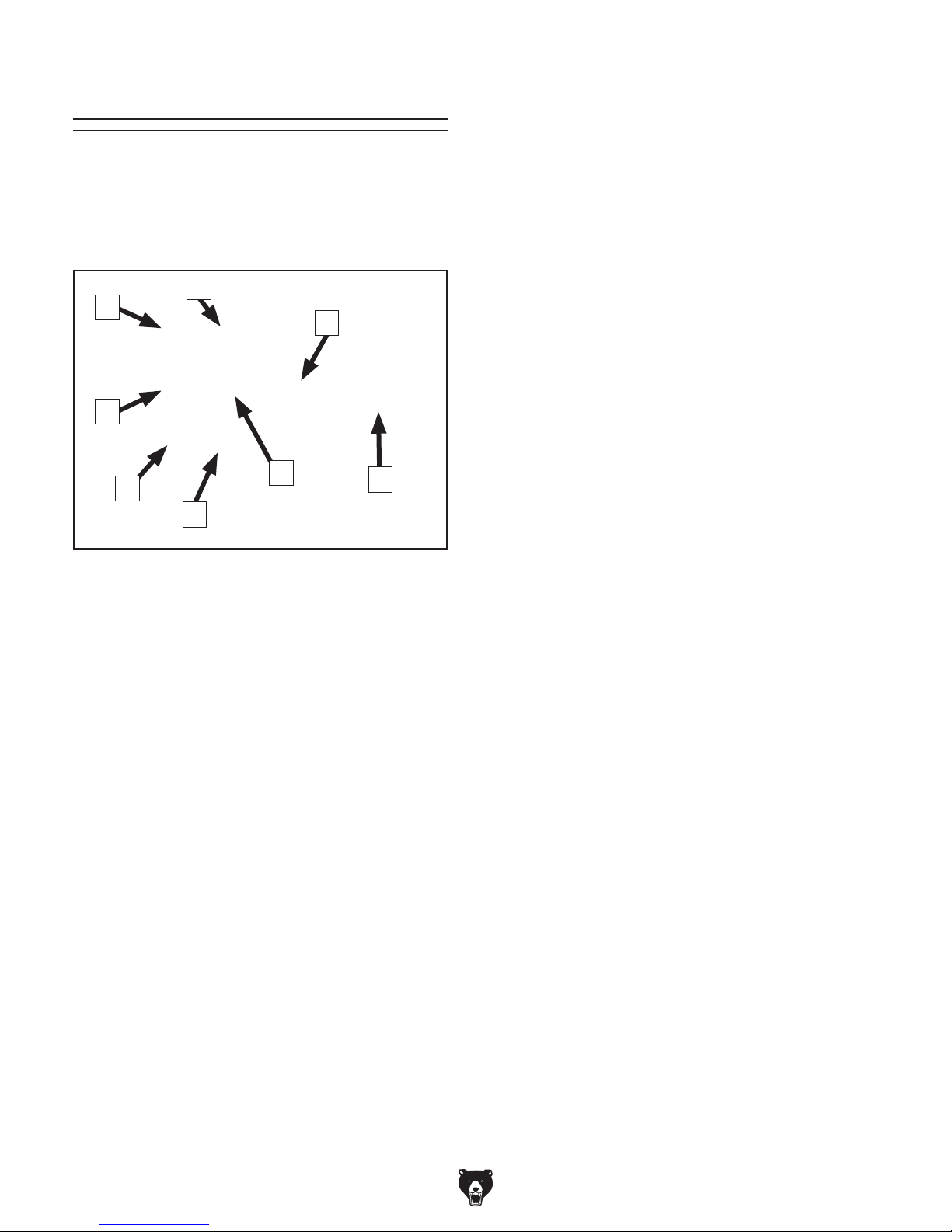
Machine Data Sheet ...................................... 5
SECTION 1: SAFETY....................................... 7
Safety Instructions for Machinery .................. 7
Additional Safety for Mill/Drills ....................... 9
SECTION 2: POWER SUPPLY ...................... 10
Availability .................................................................10
Full-Load Current Rating ...........................................10
Circuit Requirements for 220V ..................................10
Grounding Instructions ..............................................11
Extension Cords ........................................................11
SECTION 3: SETUP ....................................... 12
Unpacking .................................................... 12
Needed for Setup ......................................... 12
Inventory ...................................................... 12
Cleanup ........................................................ 13
Site Considerations ...................................... 14
Lifting & Placing ........................................... 15
Bench Mounting ........................................... 15
Assembly ..................................................... 16
Joining Drill Chuck & Arbor .......................... 16
Lubricating Mill/Drill ...................................... 17
Test Run ...................................................... 17
Spindle Bearing Break-In ............................. 19
Inspections & Adjustments .......................... 19
SECTION 4: OPERATIONS ........................... 20
Operation Overview ..................................... 20
Downfeed Controls ...................................... 21
Identification ..............................................................21
Using Coarse Downfeed ...........................................21
Using Fine Downfeed ................................................21
Depth Stop ................................................... 21
Headstock Movement .................................. 22
Raising/Lowering Headstock .....................................22
Tilting Headstock .......................................................22
Table Travel ................................................. 23
Graduated Dials ........................................................23
X-Axis Handwheel .....................................................23
Y-Axis Handwheel .....................................................23
X-Axis Power Feed ...................................................24
Installing/Removing Tooling ......................... 24
Installing Tooling .......................................................25
Removing Tooling .....................................................25
Spindle Speed.............................................. 26
Determining Spindle Speed ......................................26
Setting Spindle Speed ...............................................26
Tapping Mode .............................................. 27
SECTION 5: ACCESSORIES ......................... 28
SECTION 6: MAINTENANCE......................... 30
Schedule ...................................................... 30
Cleaning and Protecting .............................. 30
Lubrication ................................................... 30
Headstock .................................................................31
Ball Oilers ..................................................................32
Table & Column Ways ..............................................32
Quill Outside Surface ................................................33
Table Leadscrews .....................................................33
Column Leadscrew, Nut, & Pinion Gear ...................34
Quill Rack & Pinion ...................................................34
SECTION 7: SERVICE ................................... 35
Troubleshooting ........................................... 35
Adjusting Gibs .............................................. 37
Adjusting Leadscrew Backlash .................... 37
Tightening Return Spring Tension ............... 38
SECTION 8: WIRING...................................... 39
Wiring Safety Instructions ............................ 39
Electrical Box & Control Panel Wiring ......... 40
Motor & Tapping Switches Wiring ............... 42
SECTION 9: PARTS....................................... 43
Headstock .................................................... 43
Table & Column ........................................... 46
Electrical ...................................................... 48
Accessories .................................................. 49
Labels & Cosmetics ..................................... 50
WARRANTY & RETURNS ............................. 53

-2- Model G0761 (Mfd. Since 10/13)
INTRODUCTION
Machine Description
We are proud to provide a high-quality owner’s
manual with your new machine!
We
made every effort to be exact with the
instruc-
tions, specifications, drawings, and photographs
contained inside. Sometimes we make mistakes,
but
our policy of continuous improvement
also
means that
sometimes the machine
you receive
will be slightly different than what is shown in
the manual
.
If you find this to be the case, and the difference
between the manual and machine leaves you
confused about a procedure
, check our website
for an updated version. W
e post current
manuals
and
manual updates for free on our website at
www.grizzly.com
.
Alternatively, you can call our Technical Support
for help. Before calling, please write down the
Manufacture Date
and Serial Number
stamped
into the machine ID label (see below). This infor-
mation helps us determine if updated documenta-
tion is available for your machine.
Manufacture Date
Serial Number
Manual Accuracy
We stand behind our machines. If you have
any questions or need help, use the information
below to contact us. Before contacting, please get
the serial number and manufacture date of your
machine. This will help us help you faster.
Grizzly Technical Support
1203 Lycoming Mall Circle
Muncy, PA 17756
Phone: (570) 546-9663
Email: [email protected]
We want your feedback on this manual. What did
you like about it? Where could it be improved?
Please take a few minutes to give us feedback.
Grizzly Documentation Manager
P.O. Box 2069
Bellingham, WA 98227-2069
Email: [email protected]
Contact Info
The mill/drill is used to shape metal workpieces
by removing material with the use of a rotating
cutting tool.
In milling operations, the cutting tool rotates in
place while the workpiece is drawn across it by
moving the table.
In drilling operations, the workpiece is held sta-
tionary on the table while the rotating cutting tool
moves up-and-down with the movement of the
spindle.
In tapping operations, the tap is lowered into the
workpiece and threads itself down until the depth
stop is reached. At this point, spindle direction
automatically reverses and the tap rotates back-
wards out of the hole.

Model G0761 (Mfd. Since 10/13) -3-
Identification
To reduce your risk of
serious injury, read this
entire manual BEFORE
using machine.
Drawbar
Cover
Motor
Z-Axis
Lock
Y-Axis
Handwheel
X-Axis
Power Feed
Spindle
Control
Panel
Fine Downfeed
Handwheel
Depth Stop
& Scale
Power Feed
Stop
X-Axis
Table Locks
Coarse Downfeed
Handle
X-Axis
Handwheel
Table
Downfeed
Selector
Knob
Power Feed
Stop
Y-Axis
Table Lock
Dovetail
Column
Headstock
Tilt Scale
Gearbox
Levers
Quill
Lock

-4- Model G0761 (Mfd. Since 10/13)
Basic Controls
Use Figure 1 and the descriptions below to gain
a basic understanding of the control panel and
spindle speed controls. Knowing this information
is required to safely complete the Test Run in the
SETUP section.
A. POWER Lamp: Illuminates when the machine
is connected to power.
B. Mode Switch: Sets the spindle mode to
either drilling/milling or tapping.
C. High/Low Range Lever: Selects either high
or low spindle speed range.
D. Spindle Speed Lever: Selects one of three
spindle speeds in the selected speed range.
E. SPINDLE REVERSE Button: Starts coun-
terclockwise spindle rotation (as viewed from
above). The spindle must be completely
stopped before this button is pushed.
F. EMERGENCY STOP Button: Cuts power
to the spindle motor and remains depressed
until reset. Twist clockwise until it pops out to
reset.
G. STOP Button: Stops spindle rotation.
H. SPINDLE FORWARD Button: Starts clock-
wise spindle rotation (as viewed from above).
The spindle must be completely stopped
before this button is pushed.
Figure 1. Control panel and spindle speed
controls.
A
B
C
F
G
H
ED

Model G0761 (Mfd. Since 10/13) -5-
The information contained herein is deemed accurate as of 5/14/2014 and represents our most recent product specifications.
Due to our ongoing improvement efforts, this information may not accurately describe items previously purchased. PAGE 1 OF 2Model G0761
MACHINE DATA
SHEET
Customer Service #: (570) 546-9663 · To Order Call: (800) 523-4777 · Fax #: (800) 438-5901
MODEL G0761 HEAVY-DUTY BENCHTOP MILL/DRILL WITH
POWER FEED AND TAPPING
Product Dimensions:
Weight.............................................................................................................................................................. 716 lbs.
Width (side-to-side) x Depth (front-to-back) x Height............................................................... 49-5/8 x 30-3/4 x 57 in.
Footprint (Length x Width)............................................................................................................... 21-5/8 x 17-3/4 in.
Shipping Dimensions:
Type.......................................................................................................................................................... Wood Crate
Content........................................................................................................................................................... Machine
Weight.............................................................................................................................................................. 772 lbs.
Length x Width x Height....................................................................................................................... 34 x 30 x 46 in.
Electrical:
Power Requirement............................................................................................................ 220V, Single-Phase, 60Hz
Prewired Voltage.................................................................................................................................................. 220V
Full-Load Current Rating....................................................................................................................................... 8.6A
Minimum Circuit Size.............................................................................................................................................. 15A
Power Cord Included.............................................................................................................................................. Yes
Power Cord Length................................................................................................................................................. 5 ft.
Power Cord Gauge......................................................................................................................................... 14 AWG
Plug Included........................................................................................................................................................... No
Recommended Plug Type..................................................................................................................................... 6-15
Switch Type........................................................................................... Control Panel w/ Magnetic Switch Protection
Motors:
Main
Type................................................................................................................. TEFC Capacitor-Start Induction
Horsepower................................................................................................................................................ 2 HP
Phase............................................................................................................................................ Single-Phase
Amps........................................................................................................................................................... 8.6A
Speed................................................................................................................................................ 1720 RPM
Power Transfer ................................................................................................................................. Gear Drive
Bearings..................................................................................................... Shielded & Permanently Lubricated
Main Specifications:
Operation Info
Spindle Travel........................................................................................................................................ 4-3/4 in.
Max Distance Spindle to Column........................................................................................................ 10-1/8 in.
Max Distance Spindle to Table............................................................................................................ 18-1/8 in.
Longitudinal Table Travel (X-Axis).............................................................................................................. 22 in
Cross Table Travel (Y-Axis).................................................................................................................. 7-1/2 in.
Vertical Head Travel (Z-Axis)............................................................................................................... 13-3/4 in
Head Tilt (Left/Right)........................................................................................................ Right 45, Left 45 deg.
Drilling Capacity for Cast Iron................................................................................................................ 1-3/4 in.
Drilling Capacity for Steel...................................................................................................................... 1-1/4 in.
End Milling Capacity............................................................................................................................. 1-1/4 in.
Face Milling Capacity............................................................................................................................ 3-1/8 in.
Machine Data Sheet

-6- Model G0761 (Mfd. Since 10/13)
The information contained herein is deemed accurate as of 5/14/2014 and represents our most recent product specifications.
Due to our ongoing improvement efforts, this information may not accurately describe items previously purchased. PAGE 2 OF 2Model G0761
Table Info
Table Length........................................................................................................................................ 31-1/2 in.
Table Width........................................................................................................................................... 9-1/2 in.
Table Thickness.................................................................................................................................... 2-1/2 in.
Number of T-Slots............................................................................................................................................ 3
T-Slot Size................................................................................................................................................ 1/2 in.
T-Slots Centers...................................................................................................................................... 3-1/8 in.
Spindle Info
Spindle Taper............................................................................................................................................... R-8
Number of Vertical Spindle Speeds.................................................................................................................. 6
Range of Vertical Spindle Speeds............................................................................................... 90–1970 RPM
Quill Diameter.............................................................................................................................................. 3 in.
Drawbar Thread Size............................................................................................................................. 7/16-20
Drawbar Length................................................................................................................................... 17-3/4 in.
Spindle Bearings........................................................................... High-Precision "P5" Tapered Roller Bearing
Construction
Spindle Housing/Quill........................................................................................................................... Cast Iron
Table.................................................................................................................................................... Cast Iron
Head.................................................................................................................................................... Cast Iron
Column/Base....................................................................................................................................... Cast Iron
Paint Type/Finish.................................................................................................................................... Enamel
Other Specifications:
Country Of Origin ............................................................................................................................................... China
Warranty ........................................................................................................................................................... 1 Year
Serial Number Location .................................................................................................................................. ID Label
Sound Rating ................................................................................................................................................... <80 dB
ISO 9001 Factory ................................................................................................................................................. Yes
CSA Certified .......................................................................................................................................................... No
Features:
Hand-scraped dovetail ways
Tapping capability
High-precision P5 tapered-roller spindle bearings
Coolant trough built into table
45 degree right/left head tilt
Accessories Included:
Drill chuck 1-13mm with B16 taper
Tool box
Oil bottle

Model G0761 (Mfd. Since 10/13) -7-
ELECTRICAL EQUIPMENT INJURY RISKS. You
can be shocked, burned, or killed by touching live
electrical components or improperly grounded
machinery. To reduce this risk, only allow qualified
service personnel to do electrical installation or
repair work, and always disconnect power before
accessing or exposing electrical equipment.
DISCONNECT POWER FIRST.
Always discon-
nect machine from power supply BEFORE making
adjustments, changing tooling, or servicing machine.
This prevents an injury risk from unintended startup
or contact with live electrical components.
EYE PROTECTION. Always wear ANSI-approved
safety glasses or a face shield when operating or
observing machinery to reduce the risk of eye
injury or blindness from flying particles. Everyday
eyeglasses are NOT approved safety glasses.
OWNER’S MANUAL. Read and understand this
owner’s manual BEFORE using machine.
TRAINED OPERATORS ONLY. Untrained oper-
ators have a higher risk of being hurt or killed.
Only allow trained/supervised people to use this
machine. When machine is not being used, dis-
connect power, remove switch keys, or lock-out
machine to prevent unauthorized use—especially
around children. Make workshop kid proof!
DANGEROUS ENVIRONMENTS. Do not use
machinery in areas that are wet, cluttered, or have
poor lighting. Operating machinery in these areas
greatly increases the risk of accidents and injury.
MENTAL ALERTNESS REQUIRED. Full mental
alertness is required for safe operation of machin-
ery. Never operate under the influence of drugs or
alcohol, when tired, or when distracted.
For Your Own Safety, Read Instruction
Manual Before Operating This Machine
The purpose of safety symbols is to attract your attention to possible hazardous conditions.
This manual uses a series of symbols and signal words intended to convey the level of impor-
tance of the safety messages. The progression of symbols is described below. Remember that
safety messages by themselves do not eliminate danger and are not a substitute for proper
accident prevention measures. Always use common sense and good judgment.
Indicates a potentially hazardous situation which, if not avoided,
MAY result in minor or moderate injury. It may also be used to alert
against unsafe practices.
Indicates a potentially hazardous situation which, if not avoided,
COULD result in death or serious injury.
Indicates an imminently hazardous situation which, if not avoided,
WILL result in death or serious injury.
This symbol is used to alert the user to useful information about
proper operation of the machine.
NOTICE
Safety Instructions for Machinery
SECTION 1: SAFETY

-8- Model G0761 (Mfd. Since 10/13)
WEARING PROPER APPAREL. Do not wear
clothing, apparel or jewelry that can become
entangled in moving parts. Always tie back or
cover long hair. Wear non-slip footwear to avoid
accidental slips, which could cause loss of work-
piece control.
HAZARDOUS DUST. Dust created while using
machinery may cause cancer, birth defects, or
long-term respiratory damage. Be aware of dust
hazards associated with each workpiece material,
and always wear a NIOSH-approved respirator to
reduce your risk.
HEARING PROTECTION. Always wear hear-
ing protection when operating or observing loud
machinery. Extended exposure to this noise
without hearing protection can cause permanent
hearing loss.
REMOVE ADJUSTING TOOLS. Tools left on
machinery can become dangerous projectiles
upon startup. Never leave chuck keys, wrenches,
or any other tools on machine. Always verify
removal before starting!
USE CORRECT TOOL FOR THE JOB. Only use
this tool for its intended purpose—do not force
it or an attachment to do a job for which it was
not designed. Never make unapproved modifica-
tions—modifying tool or using it differently than
intended may result in malfunction or mechanical
failure that can lead to personal injury or death!
AWKWARD POSITIONS. Keep proper footing
and balance at all times when operating machine.
Do not overreach! Avoid awkward hand positions
that make workpiece control difficult or increase
the risk of accidental injury.
CHILDREN & BYSTANDERS. Keep children and
bystanders at a safe distance from the work area.
Stop using machine if they become a distraction.
GUARDS & COVERS. Guards and covers reduce
accidental contact with moving parts or flying
debris. Make sure they are properly installed,
undamaged, and working correctly.
FORCING MACHINERY. Do not force machine.
It will do the job safer and better at the rate for
which it was designed.
NEVER STAND ON MACHINE. Serious injury
may occur if machine is tipped or if the cutting
tool is unintentionally contacted.
STABLE MACHINE. Unexpected movement dur-
ing operation greatly increases risk of injury or
loss of control. Before starting, verify machine is
stable and mobile base (if used) is locked.
USE RECOMMENDED ACCESSORIES. Consult
this owner’s manual or the manufacturer for rec-
ommended accessories. Using improper acces-
sories will increase the risk of serious injury.
UNATTENDED OPERATION. To reduce the
risk of accidental injury, turn machine OFF and
ensure all moving parts completely stop before
walking away. Never leave machine running
while unattended.
MAINTAIN WITH CARE. Follow all maintenance
instructions and lubrication schedules to keep
machine in good working condition. A machine
that is improperly maintained could malfunction,
leading to serious personal injury or death.
CHECK DAMAGED PARTS. Regularly inspect
machine for any condition that may affect safe
operation. Immediately repair or replace damaged
or mis-adjusted parts before operating machine.
MAINTAIN POWER CORDS. When disconnect-
ing cord-connected machines from power, grab
and pull the plug—NOT the cord. Pulling the cord
may damage the wires inside. Do not handle
cord/plug with wet hands. Avoid cord damage by
keeping it away from heated surfaces, high traffic
areas, harsh chemicals, and wet/damp locations.
EXPERIENCING DIFFICULTIES. If at any time
you experience difficulties performing the intend-
ed operation, stop using the machine! Contact our
Technical Support at (570) 546-9663.

Model G0761 (Mfd. Since 10/13) -9-
Additional Safety for Mill/Drills
UNDERSTAND ALL CONTROLS. Make sure
you understand the function and proper use of all
controls before starting. This will help you avoid
making mistakes that result in serious injury.
WEAR FACE SHIELD. Always wear a face shield
in addition to safety glasses. This provides more
complete protection for your face than safety
glasses alone.
REMOVE CHUCK KEY & SPINDLE TOOLS.
Always remove chuck key, drawbar wrench, and
other tools used on the spindle immediately after
use. This will prevent them from being thrown by
the spindle upon startup.
PROPERLY SECURE CUTTER. Firmly secure
cutting tool or drill bit so it does not fly out of spin-
dle during operation.
USE CORRECT SPINDLE SPEED. Follow rec-
ommended speeds and feeds for each size and
type of cutting tool. This helps ensure best cutting
results and avoid tool breakage during operation.
INSPECT CUTTING TOOL. Inspect cutting tools
for sharpness, chips, or cracks before each use.
Replace dull, chipped, or cracked cutting tools
immediately.
ALLOW SPINDLE TO STOP. To minimize your
risk of entanglement, always allow spindle to stop
on its own. DO NOT stop spindle using your hand
or any other object.
The primary risks of operating a Mill/Drill are as follows: You can be seriously injured or killed
by getting clothing, jewelry, or long hair entangled with rotating cutter. You can be severely cut
or your fingers can be amputated by contacting the rotating cutter. You can be blinded or struck
with great force by broken cutting tools, metal chips, workpieces, or adjustment tools thrown
from the rotating spindle. To reduce your risk of serious injury when operating this machine,
completely heed and understand the following:
SECURE WORKPIECE TO TABLE. Clamp work-
piece to table or secure in a vise mounted to table,
so workpiece cannot unexpectedly shift or spin
during operation. NEVER hold workpiece by hand
during operation.
CLEAN MACHINE SAFELY. Metal chips or shav-
ings can be razor sharp. DO NOT clear chips
by hand or compressed air that can force chips
farther into machine—use a brush or vacuum
instead. Never clear chips while spindle is turning.
PROPERLY MAINTAIN MACHINE. Keep machine
in proper working condition to help ensure that it
functions safely and all guards and other compo-
nents work as intended. Perform routine inspec-
tions and all necessary maintenance. Never oper-
ate machine with damaged or worn parts that can
break or result in unexpected movement during
operation.
DISCONNECT POWER FIRST. To reduce risk of
electrocution or injury from unexpected startup,
make sure mill/drill is turned OFF, disconnected
from power, and all moving parts have come to
a complete stop before changing cutting tools or
starting any inspection, adjustment, or mainte-
nance procedure.
POWER DISRUPTION. In the event of a local
power outage during operation, turn spindle switch
OFF to avoid a possible sudden startup once
power is restored.

-10- Model G0761 (Mfd. Since 10/13)
SECTION 2: POWER SUPPLY
Availability
Before installing the machine, consider the avail-
ability and proximity of the required power supply
circuit. If an existing circuit does not meet the
requirements for this machine, a new circuit must
be installed. To minimize the risk of electrocution,
fire, or equipment damage, installation work and
electrical wiring must be done by an electrican or
qualified service personnel in accordance with all
applicable codes and standards.
Electrocution, fire, or
equipment damage may
occur if machine is not
correctly grounded and
connected to the power
supply.
Full-Load Current Rating
The full-load current rating is the amperage a
machine draws at 100% of the rated output power.
On machines with multiple motors, this is the
amperage drawn by the largest motor or sum of all
motors and electrical devices that might operate
at one time during normal operations.
Full-Load Current Rating at 220V .... 8.6 Amps
The full-load current is not the maximum amount
of amps that the machine will draw. If the machine
is overloaded, it will draw additional amps beyond
the full-load rating.
If the machine is overloaded for a sufficient length
of time, damage, overheating, or fire may result—
especially if connected to an undersized circuit.
To reduce the risk of these hazards, avoid over-
loading the machine during operation and make
sure it is connected to a power supply circuit that
meets the requirements in the following section.
Circuit Requirements for 220V
This machine is prewired to operate on a 220V
power supply circuit that has a verified ground and
meets the following requirements:
Nominal Voltage ................... 220V, 230V, 240V
Cycle ..........................................................60 Hz
Phase .................................................... 1-Phase
Power Supply Circuit ......................... 15 Amps
Plug/Receptacle ............................. NEMA 6-15
For your own safety and protection of
property, consult an electrician if you are
unsure about wiring practices or electrical
codes in your area.
Note: The circuit requirements listed in this man-
ual apply to a dedicated circuit—where only one
machine will be running at a time. If this machine
will be connected to a shared circuit where mul-
tiple machines will be running at the same time,
consult a qualified electrician to ensure that the
circuit is properly sized for safe operation.
A power supply circuit includes all electrical
equipment between the breaker box or fuse panel
in the building and the machine. The power sup-
ply circuit used for this machine must be sized to
safely handle the full-load current drawn from the
machine for an extended period of time. (If this
machine is connected to a circuit protected by
fuses, use a time delay fuse marked D.)

Model G0761 (Mfd. Since 10/13) -11-
Extension Cords
We do not recommend using an extension cord
with this machine.
If you must use an extension
cord, only use it if absolutely necessary and only
on a temporary basis.
Extension cords cause voltage drop, which may
damage electrical components and shorten motor
life. Voltage drop increases as the extension cord
size gets longer and the gauge size gets smaller
(higher gauge numbers indicate smaller sizes).
Any extension cord used with this machine must
contain a ground wire, match the required plug
and receptacle, and meet the following require-
ments:
Minimum Gauge Size ...........................14 AWG
Maximum Length (Shorter is Better).......50 ft.
Grounding Instructions
This machine MUST be grounded. In the event
of certain malfunctions or breakdowns, grounding
reduces the risk of electric shock by providing a
path of least resistance for electric current.
Figure 2. Typical 6-15 plug and receptacle.
Grounding Prong
Current Carrying Prongs
6-15 PLUG
GROUNDED
6-15 RECEPTACLE
Improper connection of the equipment-grounding
wire can result in a risk of electric shock. The
wire with green insulation (with or without yellow
stripes) is the equipment-grounding wire. If repair
or replacement of the power cord or plug is nec-
essary, do not connect the equipment-grounding
wire to a live (current carrying) terminal.
Check with a qualified electrician or service per-
sonnel if you do not understand these grounding
requirements, or if you are in doubt about whether
the tool is properly grounded. If you ever notice
that a cord or plug is damaged or worn, discon-
nect it from power, and immediately replace it with
a new one.
Serious injury could occur if you connect
the machine to power before completing the
setup process. DO NOT connect to power
until instructed later in this manual.
The power cord and plug specified under “Circuit
Requirements for 220V”
on the previous page
has an equipment-grounding wire and a ground-
ing prong. The plug must only be inserted into
a matching receptacle (outlet) that is properly
installed and grounded in accordance with all
local codes and ordinances (see figure below).
No adapter should be used with the
required plug. If the plug does not fit the
available receptacle, or the machine must
be reconnected for use on a different type
of circuit, the reconnection must be made
by a qualified electrician and comply with all
local codes and ordinances.

-12- Model G0761 (Mfd. Since 10/13)
SECTION 3: SETUP
Your machine was carefully packaged for safe
transportation. Remove the packaging materials
from around your machine and inspect it. If you
discover any damage, please call us immediately
at (570) 546-9663
for advice.
Save the containers and all packing materials for
possible inspection by the carrier or its agent.
Otherwise, filing a freight claim can be difficult.
When you are completely satisfied with the condi
-
tion of your shipment, inventory the contents.
Unpacking
The following are needed to complete the setup
process, but are not included with your machine.
Description Qty
• Additional People ....................................... 1
• Safety Glasses ........................ 1 Per Person
• Cleaner/Degreaser (Page 13) .... As Needed
• Disposable Shop Rags ............... As Needed
• Forklift ......................................................... 1
• Lifting Strap (rated for at least 1000 lbs.) ... 1
• Mounting Hardware (Page 15) ... As Needed
• Flat Head Screwdriver #2 ........................... 1
• Brass Hammer (Page 16) .......................... 1
• Mineral Spirits (Page 16) ............ As Needed
Needed for Setup
Inventory
The following is a list of items shipped with your
machine. Before beginning setup, lay these items
out and inventory them.
If any non-proprietary parts are missing (e.g. a
nut or a washer), we will gladly replace them; or
for the sake of expediency, replacements can be
obtained at your local hardware store.
Small Item Inventory (Figure 3) Qty
A. Handwheel Handles w/Screws ................... 2
B. T-Bolts M12-1.75 x 55 w/Washers & Nuts .. 2
C. Bottle for Oil ............................................... 1
D. Toolbox ....................................................... 1
E. Wrenches 17/19, 22/24mm ....................1 Ea
F. Hex Wrenches 3, 4, 5, 10mm ................1 Ea
G. Drift Key ...................................................... 1
H. Drill Chuck w/Chuck Key B16, 1–13mm ..... 1
I. Spindle Sleeve R-8 x MT#3 ....................... 1
J. Drill Chuck Arbor R-8 x B16 ....................... 1
K. Spindle Sleeve MT#3 x MT#2 .................... 1
Figure 3. Small item inventory.
K
A
B
C
D
E
F
G
H
I
J
NOTICE
If you cannot find an item on this list, care-
fully check around/inside the machine and
packaging materials. Often, these items get
lost in packaging materials while unpack-
ing or they are pre-installed at the factory.

Model G0761 (Mfd. Since 10/13) -13-
The unpainted surfaces of your machine are
coated with a heavy-duty rust preventative that
prevents corrosion during shipment and storage.
This rust preventative works extremely well, but it
will take a little time to clean.
Be patient and do a thorough job cleaning your
machine. The time you spend doing this now will
give you a better appreciation for the proper care
of your machine's unpainted surfaces.
There are many ways to remove this rust preven-
tative, but the following steps work well in a wide
variety of situations. Always follow the manufac-
turer’s instructions with any cleaning product you
use and make sure you work in a well-ventilated
area to minimize exposure to toxic fumes.
Before cleaning, gather the following:
• Disposable rags
• Cleaner/degreaser (WD•40 works well)
• Safety glasses & disposable gloves
• Plastic paint scraper (optional)
Basic steps for removing rust preventative:
1.
Put on safety glasses.
2.
Coat the rust preventative with a liberal
amount of cleaner/degreaser, then let it soak
for 5–10 minutes.
3.
Wipe off the surfaces. If your cleaner/degreas-
er is effective, the rust preventative will wipe
off easily. If you have a plastic paint scraper,
scrape off as much as you can first, then wipe
off the rest with the rag.
4.
Repeat Steps 2–3 as necessary until clean,
then coat all unpainted surfaces with a quality
metal protectant to prevent rust.
Gasoline and petroleum
products have low flash
points and can explode
or cause fire if used to
clean machinery. Avoid
using these products
to clean machinery.
Many cleaning solvents
are toxic if inhaled. Only
work in a well-ventilated
area.
NOTICE
Avoid chlorine-based solvents, such as
acetone or brake parts cleaner, that may
damage painted surfaces.
T23692—Orange Power Degreaser
A great product for removing the waxy shipping
grease from your machine during clean up.
Figure 4. T23692 Orange Power Degreaser.
Cleanup

-14- Model G0761 (Mfd. Since 10/13)
Site Considerations
Figure 5. Minimum working clearances.
621⁄2"
31"
495⁄8"
Weight Load
Refer to the Machine Data Sheet for the weight
of your machine. Make sure that the surface upon
which the machine is placed will bear the weight
of the machine, additional equipment that may be
installed on the machine, and the heaviest work-
piece that will be used. Additionally, consider the
weight of the operator and any dynamic loading
that may occur when operating the machine.
Space Allocation
Consider the largest size of workpiece that will
be processed through this machine and provide
enough space around the machine for adequate
operator material handling or the installation of
auxiliary equipment. With permanent installations,
leave enough space around the machine to open
or remove doors/covers as required by the main-
tenance and service described in this manual.
See below for required space allocation.
Physical Environment
The physical environment where the machine is
operated is important for safe operation and lon-
gevity of machine components. For best results,
operate this machine in a dry environment that is
free from excessive moisture, hazardous chemi-
cals, airborne abrasives, or extreme conditions.
Extreme conditions for this type of machinery are
generally those where the ambient temperature
range exceeds 41°–104°F; the relative humidity
range exceeds 20–95% (non-condensing); or the
environment is subject to vibration, shocks, or
bumps.
Electrical Installation
Place this machine near an existing power source.
Make sure all power cords are protected from
traffic, material handling, moisture, chemicals,
or other hazards. Make sure to leave access to
a means of disconnecting the power source or
engaging a lockout/tagout device, if required.
Lighting
Lighting around the machine must be adequate
enough that operations can be performed safely.
Shadows, glare, or strobe effects that may distract
or impede the operator must be eliminated.
Children or untrained people
may be seriously injured by
this machine. Only install in an
access restricted location.

Model G0761 (Mfd. Since 10/13) -15-
Lifting & Placing
To move machine into position:
1. Move shipping crate next to workbench or
stand, then unbolt machine from pallet.
2. Move table as close to column as possible,
and raise headstock to its highest position.
This will help balance machine when moving.
3. Tighten Z-axis locks to avoid sudden shifts
when lifting.
4. Place a lifting strap under headstock, as
shown in Figure 6, connect strap ends to a
forklift, then lift and place machine.
Figure 6. Recommended lifting strap position.
Lifting
Strap Lifting
Strap
Bench Mounting
Figure 8. Example of a "Direct Mount" setup.
Machine Base
Workbench
Lag Screw
Flat Washer
Another option is a "Direct Mount" (see example
below) where the machine is secured directly to
the workbench with lag screws and washers.
The base of this machine has mounting holes
that allow it to be fastened to a workbench or
other mounting surface to prevent it from moving
during operation and causing accidental injury or
damage.
The strongest mounting option is a "Through
Mount" (see example below) where holes are
drilled all the way through the workbench—and
hex bolts, washers, and hex nuts are used to
secure the machine in place.
Machine Base
Workbench
Hex
Bolt
Flat Washer
Flat Washer
Lock Washer
Hex Nut
Figure 7. Example of a "Through Mount" setup.
Number of Mounting Holes ............................ 4
Diameter of Mounting Hardware................. 1⁄2"
HEAVY LIFT!
Straining or crushing injury
may occur from improperly
lifting machine or some of
its parts. To reduce this
risk, get help from other
people and use a forklift
(or other lifting equipment)
rated for weight of this
machine.

-16- Model G0761 (Mfd. Since 10/13)
Assembly
The mill/drill was fully assembled at the factory
except for the handwheel handles.
Use a flat-head screwdriver to attach the
handwheels handles, as shown in Figure 9.
Figure 9. Handwheel handles attached.
Handwheel Handles
An arbor is included for the drill chuck that
comes with this machine. The following procedure
describes how to install the arbor in the chuck.
After the arbor is installed in the drill chuck, it
is very difficult to separate the assembly. If you
would like to use a different chuck in the future,
we recommend obtaining a new arbor.
Important: DO NOT install the drill chuck and
arbor into the spindle until AFTER the test run.
To join the drill chuck and arbor:
1. Use mineral spirits to clean drill chuck and
arbor mating surfaces, especially the bore.
2. Retract chuck jaws completely into chuck.
3. Insert small end of arbor into chuck.
4. Hold assembly by arbor and tap chuck onto
a block of wood with medium force, as illus-
trated in Figure 10.
Joining Drill Chuck
& Arbor
Figure 10. Tapping drill chuck/arbor on block of
wood.
5. Try to separate drill chuck and arbor by hand .
If you can pull them apart, repeat this proce-
dure.

Model G0761 (Mfd. Since 10/13) -17-
HEADSTOCK MUST
BE FILLED WITH OIL!
OIL MAY NOT BE
SHIPPED WITH MACHINE!
Refer to Lubrication Section
for Correct Oil Type.
The headstock oil reservoir must have the proper
amount of oil in it before the mill/drill can be oper-
ated for the first time.
Damage caused by running the mill/drill without
oil in the reservoir will not be covered under war-
ranty. Refer to the Lubrication subsection, begin-
ning on Page 30, for details on how to check and
add oil.
Lubricating Mill/Drill Test Run
Once assembly is complete, test run the machine
to ensure it is properly connected to power and
safety components are functioning properly.
If you find an unusual problem during the test run,
immediately stop the machine, disconnect it from
power, and fix the problem BEFORE operating the
machine again. The
Troubleshooting
table in the
SERVICE section of this manual can help.
To test run the mill/drill:
1. Clear all setup tools away from machine.
2. Connect machine to power supply. Power
lamp should light.
DO NOT start machine until all preceding
setup instructions have been performed.
Operating an improperly setup machine
may result in malfunction or unexpect-
ed results that can lead to serious injury,
death, or machine/property damage.
Serious injury or death can result from
using this machine BEFORE understanding
its controls and related safety information.
DO NOT operate, or allow others to operate,
machine until the information is understood.

-18- Model G0761 (Mfd. Since 10/13)
7. Press SPINDLE FORWARD button. Spindle
should rotate clockwise (as viewed from top)
and machine should run smoothly with little to
no vibration or rubbing noises.
8. Press STOP button and wait for spindle to
completely stop.
9. Press SPINDLE REVERSE button. Spindle
should rotate counterclockwise (as viewed
from top).
10. Press EMERGENCY STOP button and wait
for spindle to completely stop.
11. Without resetting EMERGENCY STOP but-
ton, press SPINDLE FORWARD button.
Machine should not start.
—If machine does start (with EMERGENCY
STOP button pushed in), immediately dis-
connect power to machine. EMERGENCY
STOP safety feature is not working correct-
ly. This safety feature must work properly
before proceeding with regular operations.
Refer to Troubleshooting on Page for
help.
13. Twist EMERGENCY STOP button clockwise
to reset it.
14. Rotate mode switch right to TAPPING.
15. Use coarse downfeed lever to move spindle
down. Spindle should rotate clockwise.
16. Continue to move spindle down until it bot-
toms out at depth stop—spindle should
momentarily stop, then rotate counterclock-
wise.
17. Use coarse downfeed lever to move spindle
all the way up. Spindle rotation should stop.
Congratulations! The Test Run is complete.
Continue to the next subsection, Spindle Bearing
Break-In.
EMERGENCY STOP
Button
Figure 12. Twisting EMERGENCY STOP button
to reset it.
4. Rotate mode switch left to DRILLING/
MILLING.
5. Shift high/low range lever right to “L” and
spindle speed lever left to “2”. This selects a
spindle speed of 210 RPM (refer to spindle
speed chart on headstock).
Note: You may need to rotate spindle back-
and-forth by hand while putting pressure on
the shift lever to allow gears to mesh.
6. Twist EMERGENCY STOP button clockwise
until it pops out (see Figure 12)—this resets
button and enables power to control panel
and motor.
3. Press EMERGENCY STOP button (see
Figure 11). This will help prevent unexpected
startup when machine is connected to power.
Figure 11. Control panel and spindle speed
controls.
Stop
Button
Spindle
Direction
Buttons Spindle Range
& Speed Levers
Emergency
Stop
Mode Switch
Table of contents
Other Grizzly Drill manuals

Grizzly
Grizzly G7945 User manual

Grizzly
Grizzly G0484 User manual

Grizzly
Grizzly G7942 Quick start guide

Grizzly
Grizzly H7792 User manual

Grizzly
Grizzly G7943 User manual

Grizzly
Grizzly T10538 User manual

Grizzly
Grizzly G1131 User manual

Grizzly
Grizzly G5351 User manual

Grizzly
Grizzly H6363 Quick start guide

Grizzly
Grizzly G1126 User manual

Grizzly
Grizzly G0758 User manual

Grizzly
Grizzly G4014 User manual

Grizzly
Grizzly G7945 User manual

Grizzly
Grizzly G7945/46 User manual

Grizzly
Grizzly G3358 User manual

Grizzly
Grizzly G0795Z User manual

Grizzly
Grizzly G3183 User manual

Grizzly
Grizzly H0603 User manual

Grizzly
Grizzly G0795 User manual

Grizzly
Grizzly G8593 User manual