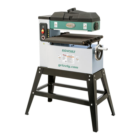
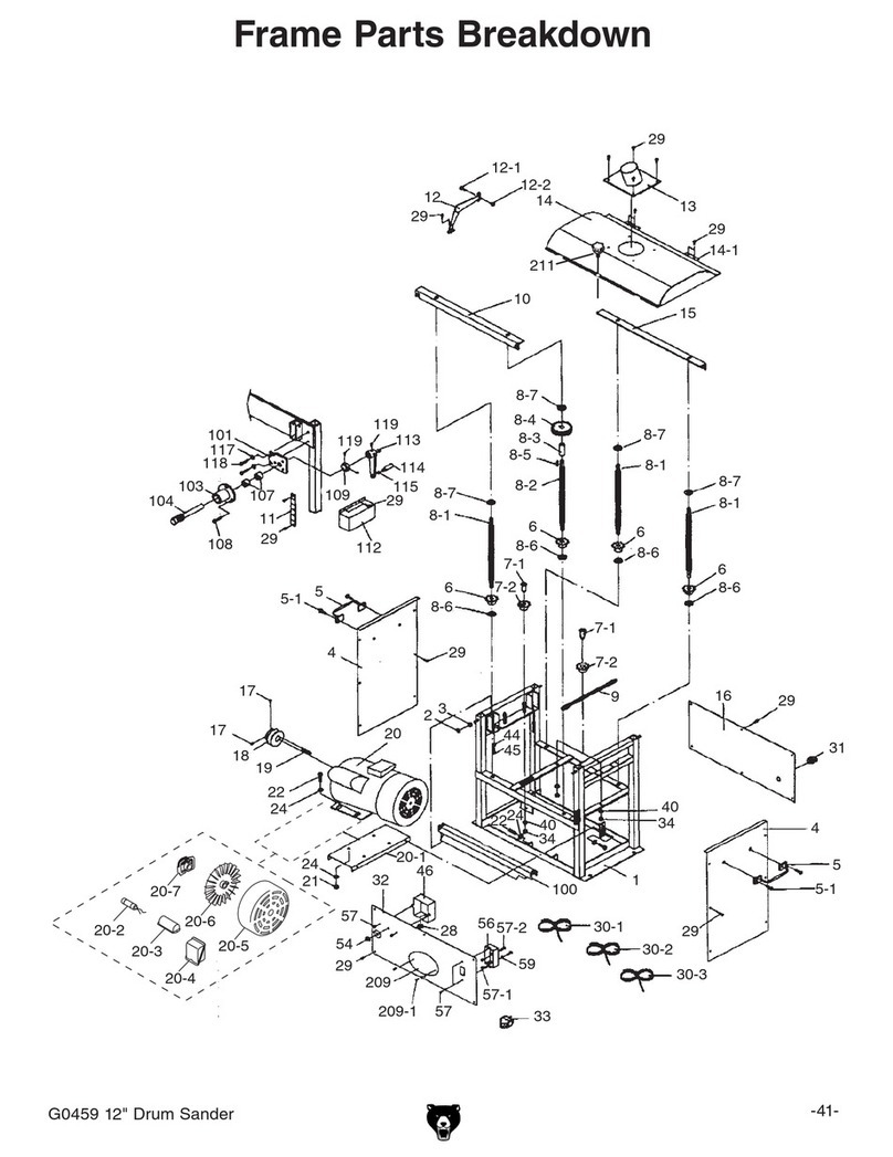
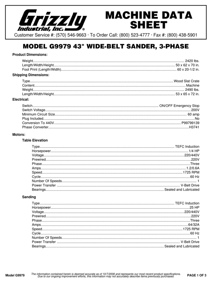
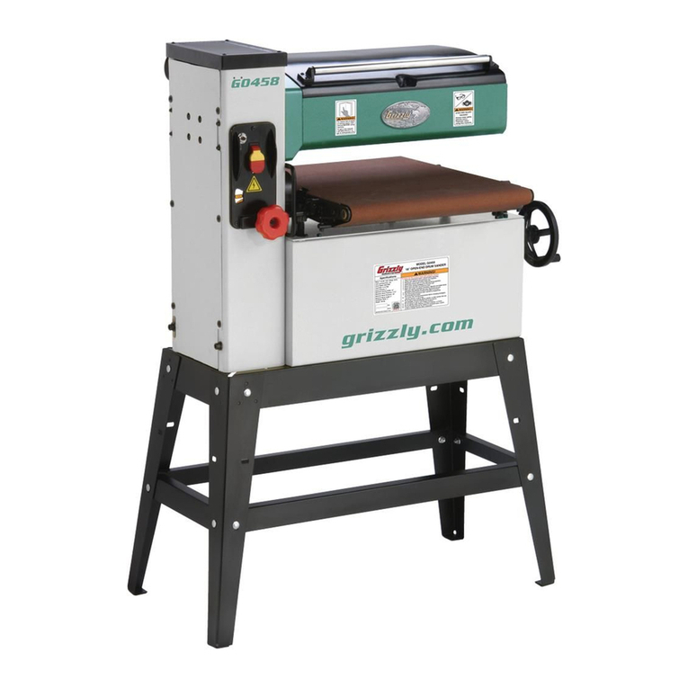
Grizzly G0458ZX User manual

COPYRIGHT © NOVEMBER, 2023 BY GRIZZLY INDUSTRIAL, INC.
WARNING: NO PORTION OF THIS MANUAL MAY BE REPRODUCED IN ANY SHAPE
OR FORM WITHOUT THE WRITTEN APPROVAL OF GRIZZLY INDUSTRIAL, INC.
#JP22949 PRINTED IN TAIWAN
The Model G0458ZX is the same machine as the Model G0458Z except for motor size, sanding drum, and
stand. Except for the differences noted in this insert, all other content in the Model G0458Z owner's manual
applies to this machine.
: To reduce the risk of serious injury, you MUST read and understand this insert—and
the entire Model G0458Z manual—BEFORE assembling, installing, or operating this machine!
If you have any further questions about this manual insert or the differences between the Model G0458ZX and
the Model G0458Z, contact our Technical Support at (570) 546-9663 or email techsupport@grizzly.com.
MODEL G0458ZX
18" OPEN-END DRUM
SANDER
MANUAL INSERT
For Machines Mfd. Since 11/23
and Owner's Manual Revised 09/22
***Keep for Future Reference***

-2- Model G0458ZX (Mfd. Since 11/23)
The information contained herein is deemed accurate as of 11/14/2023 and represents our most recent product specifications.
Due to our ongoing improvement efforts, this information may not accurately describe items previously purchased.
PAGE 1 OF 2
Model G0458ZX
MACHINE DATA
SHEET
Customer Service #: (570) 546-9663 · To Order Call: (800) 523-4777 · Fax #: (800) 438-5901
MODEL G0458ZX 18"/36" 2 HP OPEN‐END VARIABLE‐
SPEED DRUM SANDER
Product Dimensions:
Weight.............................................................................................................................................................. 202 lbs.
Width (side-to-side) x Depth (front-to-back) x Height..................................................................... 41 x 22-1/2 x 50 in.
Footprint (Length x Width)..................................................................................................................... 37 x 20-1/2 in.
Shipping Dimensions:
Type.............................................................................................................................. Cardboard Box w/Wood Skids
Content........................................................................................................................................................... Machine
Weight.............................................................................................................................................................. 224 lbs.
Length x Width x Height....................................................................................................................... 25 x 33 x 33 in.
Must Ship Upright................................................................................................................................................... Yes
Electrical:
Power Requirement............................................................................................................ 120V, Single-Phase, 60Hz
Full-Load Current Rating................................................................................................................................... 16.92A
Minimum Circuit Size.............................................................................................................................................. 20A
Connection Type....................................................................................................................................... Cord & Plug
Power Cord Included.............................................................................................................................................. Yes
Power Cord Length................................................................................................................................................. 6 ft.
Power Cord Gauge......................................................................................................................................... 14 AWG
Plug Included.......................................................................................................................................................... Yes
Included Plug Type................................................................................................................................................ 5-15
Switch Type.................................................................................................. Paddle Safety Switch w/Removable Key
Motors:
Main
Horsepower................................................................................................................................................ 2 HP
Phase............................................................................................................................................ Single-Phase
Amps............................................................................................................................................................ 16A
Speed................................................................................................................................................ 3450 RPM
Type................................................................................................................... ODP Capacitor-Start Induction
Power Transfer ............................................................................................................................................ Belt
Bearings..................................................................................................... Shielded & Permanently Lubricated
Centrifugal Switch/Contacts Type......................................................................................................... External
Conveyor Belt
Horsepower................................................................................................................................................. 90W
Amps......................................................................................................................................................... 0.92A
Speed................................................................................................................................................ 1800 RPM
Type.............................................................................................................................................. Universal DC
Power Transfer ......................................................................................................................................... Direct
MODEL G0458ZX 18" OPEN-END DRUM SANDER
The information contained herein is deemed accurate as of 11/14/2023 and represents our most recent product specifications.
Due to our ongoing improvement efforts, this information may not accurately describe items previously purchased. PAGE 1 OF 2
Model G0458ZX
MACHINE DATA
SHEET
Customer Service #: (570) 546-9663 · To Order Call: (800) 523-4777 · Fax #: (800) 438-5901
MODEL G0458ZX 18"/36" 2 HP OPEN‐END VARIABLE‐
SPEED DRUM SANDER
Product Dimensions:
Weight.............................................................................................................................................................. 202 lbs.
Width (side-to-side) x Depth (front-to-back) x Height..................................................................... 41 x 22-1/2 x 50 in.
Footprint (Length x Width)..................................................................................................................... 37 x 20-1/2 in.
Shipping Dimensions:
Type.............................................................................................................................. Cardboard Box w/Wood Skids
Content........................................................................................................................................................... Machine
Weight.............................................................................................................................................................. 224 lbs.
Length x Width x Height....................................................................................................................... 25 x 33 x 33 in.
Must Ship Upright................................................................................................................................................... Yes
Electrical:
Power Requirement............................................................................................................ 120V, Single-Phase, 60Hz
Full-Load Current Rating................................................................................................................................... 16.92A
Minimum Circuit Size.............................................................................................................................................. 20A
Connection Type....................................................................................................................................... Cord & Plug
Power Cord Included.............................................................................................................................................. Yes
Power Cord Length................................................................................................................................................. 6 ft.
Power Cord Gauge......................................................................................................................................... 14 AWG
Plug Included.......................................................................................................................................................... Yes
Included Plug Type................................................................................................................................................ 5-15
Switch Type.................................................................................................. Paddle Safety Switch w/Removable Key
Motors:
Main
Horsepower................................................................................................................................................ 2 HP
Phase............................................................................................................................................ Single-Phase
Amps............................................................................................................................................................ 16A
Speed................................................................................................................................................ 3450 RPM
Type................................................................................................................... ODP Capacitor-Start Induction
Power Transfer ............................................................................................................................................ Belt
Bearings..................................................................................................... Shielded & Permanently Lubricated
Centrifugal Switch/Contacts Type......................................................................................................... External
Conveyor Belt
Horsepower................................................................................................................................................. 90W
Amps......................................................................................................................................................... 0.92A
Speed................................................................................................................................................ 1800 RPM
Type.............................................................................................................................................. Universal DC
Power Transfer ......................................................................................................................................... Direct

Model G0458ZX (Mfd. Since 11/23) -3-
The information contained herein is deemed accurate as of 11/14/2023 and represents our most recent product specifications.
Due to our ongoing improvement efforts, this information may not accurately describe items previously purchased. PAGE 2 OF 2
Model G0458ZX
Main Specifications:
Operation Information
Number of Sanding Heads............................................................................................................................... 1
Maximum Board Width.............................................................................................................................. 36 in.
Minimum Board Width................................................................................................................................. 1 in.
Maximum Board Thickness................................................................................................................... 4-1/2 in.
Minimum Board Thickness....................................................................................................................... 1/8 in.
Minimum Board Length................................................................................................................................ 6 in.
Sandpaper Speed.................................................................................................................... 2600, 3400 FPM
Conveyor Feed Rate......................................................................................................................... 0 - 12 FPM
Sandpaper Length..................................................................................................................................... 86 in.
Sandpaper Width......................................................................................................................................... 3 in.
Drum Information
Infeed Sanding Drum Type................................................................................................................. Aluminum
Infeed Sanding Drum Size........................................................................................................................... 4 in.
Construction
Conveyor Belt................................................................................................................................... Sandpaper
Body........................................................................................................................................................... Steel
Base........................................................................................................................................................... Steel
Paint Type/Finish....................................................................................................................... Powder Coated
Other Related Information
Floor To Table Height......................................................................................................................... 35 - 40 in.
Number of Pressure Rollers............................................................................................................................. 2
Pressure Roller Type.................................................................................................................................. Steel
Pressure Roller Size................................................................................................................................ 21 mm
Conveyor Table Length....................................................................................................................... 21-5/8 in.
Conveyor Belt Length................................................................................................................................ 45 in.
Conveyor Belt Width.................................................................................................................................. 18 in.
Belt Roller Size...................................................................................................................................... 1-3/8 in.
Number of Dust Ports....................................................................................................................................... 1
Dust Port Size.............................................................................................................................................. 4 in.
Other Specifications:
Country of Origin .............................................................................................................................................. Taiwan
Warranty ........................................................................................................................................................... 1 Year
Approximate Assembly & Setup Time ...................................................................................................... 1-1/2 Hours
Serial Number Location .................................................................................................................................. ID Label
Features:
Open-Ended Design Accommodates Workpieces up to 36" Wide
Hook-and-Loop Sanding Belt
Sandpaper Conveyor Belt
4" Dust Port
Electronic Variable-Speed Conveyor Motor
4" Aluminum Sanding Drum
Durable Powder-Coated Finish
Stationary Drum Headstock
Paddle Switch with Removable Key
Easy Access for Sandpaper Changes
Built-In Mobile Base

-4- Model G0458ZX (Mfd. Since 11/23)
POWER SUPPLY
Full-Load Current Rating at 120V 16.92 Amps
Availability
Before installing the machine, consider the avail-
ability and proximity of the required power supply
circuit. If an existing circuit does not meet the
requirements for this machine, a new circuit must
be installed. To minimize the risk of electrocution,
fire, or equipment damage, installation work and
electrical wiring must be done by an electrician or
qualified service personnel in accordance with all
applicable codes and standards.
Electrocution, fire, shock,
or equipment damage
may occur if machine is
not properly grounded
and connected to power
supply.
Full-Load Current Rating
The full-load current rating is the amperage a
machine draws at 100% of the rated output power.
On machines with multiple motors, this is the
amperage drawn by the largest motor or sum of all
motors and electrical devices that might operate
at one time during normal operations.
The full-load current is not the maximum amount
of amps that the machine will draw. If the machine
is overloaded, it will draw additional amps beyond
the full-load rating.
If the machine is overloaded for a sufficient length
of time, damage, overheating, or fire may result—
especially if connected to an undersized circuit.
To reduce the risk of these hazards, avoid over-
loading the machine during operation and make
sure it is connected to a power supply circuit that
meets the specified circuit requirements.
For your own safety and protection of
property, consult an electrician if you are
unsure about wiring practices or electrical
codes in your area.
Note: Circuit requirements in this manual apply to
a dedicated circuit—where only one machine will
be running on the circuit at a time. If machine will
be connected to a shared circuit where multiple
machines may be running at the same time, con-
sult an electrician or qualified service personnel to
ensure circuit is properly sized for safe operation.
A power supply circuit includes all electrical
equipment between the breaker box or fuse panel
in the building and the machine. The power sup-
ply circuit used for this machine must be sized to
safely handle the full-load current drawn from the
machine for an extended period of time. (If this
machine is connected to a circuit protected by
fuses, use a time delay fuse marked D.)
120V Circuit Requirements
This machine is prewired to operate on a power
supply circuit that has a verified ground and meets
the following requirements:
Nominal Voltage .................... 110V, 115V, 120V
Cycle ..........................................................60 Hz
Phase ........................................... Single-Phase
Power Supply Circuit ......................... 20 Amps
Plug/Receptacle ............................. NEMA 5-15
Serious injury could occur if you connect
machine to power before completing setup
process. DO NOT connect to power until
instructed later in this manual.

Model G0458ZX (Mfd. Since 11/23) -5-
Minimum Gauge Size ...........................12 AWG
Maximum Length (Shorter is Better).......50 ft.
Grounding & Plug Requirements
This machine MUST be grounded. In the event
of certain malfunctions or breakdowns, grounding
reduces the risk of electric shock by providing a
path of least resistance for electric current.
This machine is equipped with a power cord that
has an equipment-grounding wire and a grounding
plug. Only insert plug into a matching receptacle
(outlet) that is properly installed and grounded in
accordance with all local codes and ordinances.
DO NOT modify the provided plug!
Improper connection of the equipment-grounding
wire can result in a risk of electric shock. The
wire with green insulation (with or without yellow
stripes) is the equipment-grounding wire. If repair
or replacement of the power cord or plug is nec-
essary, do not connect the equipment-grounding
wire to a live (current carrying) terminal.
Check with a qualified electrician or service per-
sonnel if you do not understand these grounding
requirements, or if you are in doubt about whether
the tool is properly grounded. If you ever notice
that a cord or plug is damaged or worn, discon-
nect it from power, and immediately replace it with
a new one.
Extension Cords
We do not recommend using an extension cord
with this machine. If you must use an extension
cord, only use it if absolutely necessary and only
on a temporary basis.
Extension cords cause voltage drop, which can
damage electrical components and shorten motor
life. Voltage drop increases as the extension cord
size gets longer and the gauge size gets smaller
(higher gauge numbers indicate smaller sizes).
Any extension cord used with this machine must
be in good condition and contain a ground wire
and matching plug/receptacle. Additionally, it must
meet the following size requirements:
Figure 1. Typical 5-15 plug and receptacle.
Grounding Pin
Neutral Hot
5-15 PLUG
GROUNDED
5-15 RECEPTACLE
SHOCK HAZARD!
Two-prong outlets do not meet the
grounding requirements for this machine.
Do not modify or use an adapter on the plug
provided—if it will not fit the outlet, have a
qualified electrician install the proper outlet
with a verified ground.

-6- Model G0458ZX (Mfd. Since 11/23)
Needed for Setup
The following are needed to complete the setup
process, but are not included with your machine:
Description Qty
• Lifting Equipment (Rated for 280 lbs.)........ 1
• Additional People ....................................... 1
• Safety Glasses (for each person)............... 1
• Open-End Wrench or Socket 12mm .......... 1
• Open-End Wrench or Socket 13mm .......... 2
• Small Hammer or Mallet............................. 1
• Hex Wrench 4mm....................................... 1
• Hex Wrench 5mm....................................... 1
• Dust Hose 4" ............................. As Needed
• Hose Clamp 4" .......................... As Needed
• Dust Collection System .............................. 1
This machine was carefully packaged for safe
transport. When unpacking, separate all enclosed
items from packaging materials and inspect them
for shipping damage.
If items are damaged
,
please
call us immediately at (570) 546-9663.
IMPORTANT: Save all packaging materials until
you are completely satisfied with the machine and
have resolved any issues between Grizzly or the
shipping agent. You MUST have the original pack-
aging to file a freight claim. It is also extremely
helpful if you need to return your machine later.
Unpacking
This machine presents
serious injury hazards
to untrained users. Read
through this entire manu-
al to become familiar with
the controls and opera-
tions before starting the
machine!
Wear safety glasses during
the entire setup process!
HEAVY LIFT!
Straining or crushing injury
may occur from improperly
lifting machine or some of
its parts. To reduce this risk,
get help from other people
and use a forklift (or other
lifting equipment) rated for
weight of this machine.
SETUP

Model G0458ZX (Mfd. Since 11/23) -7-
Inventory
Box 1 (Figures 2—3) Qty
A. Drum Sander (Not Shown) ......................... 1
B. Top Long Brackets ..................................... 2
C. Top Short Brackets..................................... 2
D. Bottom Short Brackets ............................... 2
E. Bottom Long Brackets................................ 2
F. Stand Legs ................................................. 4
G. Caster Lock Assemblies............................. 2
H. Swivel Casters............................................ 4
I. Handwheel w/Handle ................................. 1
J. Hardware and Tools (Not Shown)
—Carriage Bolts M8-1.25 x 15 ................. 24
—Flange Nuts M8-1.25............................. 24
—Rubber Foot Pads M8-1.25 x 22............. 4
—Hex Bolts M8-1.25 x 60 .......................... 4
—Lock Nuts M8-1.25.................................. 4
—Button Head Cap Screws M8-1.25 x 16.. 8
—Hex Bolts M8-1.25 x 20........................... 4
—Hex Nuts M8-1.25 ................................... 8
—Flat Washers 8mm................................ 12
—Cap Screw M5-.8 x 35............................ 1
—Flat Washer 5mm.................................... 1
—Combination Wrench 8/12mm ................ 1
—Hex Wrenches 4, 5, 6mm .................1 Ea.
The following is a list of items shipped with your
machine. Before beginning setup, lay these items
out and inventory them.
If any non-proprietary parts are missing (e.g. a
nut or a washer), we will gladly replace them; or
for the sake of expediency, replacements can be
obtained at your local hardware store.
NOTICE
If you cannot find an item on this list, care-
fully check around/inside the machine and
packaging materials. Often, these items get
lost in packaging materials while unpack-
ing or they are pre-installed at the factory.
Figure 2. Stand components..
B
C
D
E
F
G
Figure 3. Mobile base components &
handwheel.
I
H

-8- Model G0458ZX (Mfd. Since 11/23)
Site Considerations
Figure 4. Minimum working clearances.
41"
221/2"
Ensure adequate infeed clearance.
Ensure adequate outfeed clearance.
= Electrical Connection
Feed Direction
Weight Load
Refer to the
Machine Data Sheet for the weight
of your machine. Make sure that the surface upon
which the machine is placed will bear the weight
of the machine, additional equipment that may be
installed on the machine, and the heaviest work-
piece that will be used. Additionally, consider the
weight of the operator and any dynamic loading
that may occur when operating the machine.
Space Allocation
Consider the largest size of workpiece that will
be processed through this machine and provide
enough space around the machine for adequate
operator material handling or the installation of
auxiliary equipment. With permanent installations,
leave enough space around the machine to open
or remove doors/covers as required by the main-
tenance and service described in this manual.
See below for required space allocation.
Physical Environment
The physical environment where the machine is
operated is important for safe operation and lon-
gevity of machine components. For best results,
operate this machine in a dry environment that is
free from excessive moisture, hazardous chemi-
cals, airborne abrasives, or extreme conditions.
Extreme conditions for this type of machinery are
generally those where the ambient temperature
range exceeds 41°–104°F; the relative humidity
range exceeds 20%–95% (non-condensing); or
the environment is subject to vibration, shocks,
or bumps.
Electrical Installation
Place this machine near an existing power source.
Make sure all power cords are protected from
traffic, material handling, moisture, chemicals, or
other hazards. Make sure to leave enough space
around machine to disconnect power supply or
apply a lockout/tagout device, if required.
Lighting
Lighting around the machine must be adequate
enough that operations can be performed safely.
Shadows, glare, or strobe effects that may distract
or impede the operator must be eliminated.
Children or untrained people
may be seriously injured by
this machine. Only install in an
access restricted location.

Model G0458ZX (Mfd. Since 11/23) -9-
Note: We recommend assembling the stand
upside down. To make it easier, have an assistant
hold the pieces while you assemble the stand.
DO NOT final-tighten stand bolts until
stand components have been assembled.
The machine must be fully assembled before it
can be operated. Before beginning the assembly
process, refer to
Needed for Setup
and gather
all
listed items.
To ensure the assembly process
goes smoothly, first clean any
parts that are
cov-
ered or coated in heavy-duty rust preventative (if
applicable).
Assembly
HEAVY LIFT!
Straining or crushing injury
may occur from improperly
lifting machine or some of
its parts. To reduce this risk,
get help from other people
and use a forklift (or other
lifting equipment) rated for
weight of this machine.
To assemble sander:
1. Move sander pallet/box to an appropriate
location, as described in Site Considerations
on Page 8. Leave sander on pallet until
instructed to move it in Step 17.
4. Secure a second leg to top and bottom long
brackets, as shown in Figure 6.
3. Mount a bottom long bracket to stand leg and
secure by hand with (1) M8-1.25 x 15 carriage
bolt and (1) M8-1.25 flange nut, as shown in
Figure 5.
Figure 5. Top and bottom long brackets secured
to stand leg.
Top Long Bracket
Leg
Bottom Long
Bracket
x 3
Leg
Figure 6. Completed stand leg assembly.
x 3
2. Mount a top long bracket to a stand leg and
secure by hand with (2) M8-1.25 x 15 carriage
bolts and (2) M8-1.25 flange nuts, as shown
in Figure 5.
5. Repeat Steps 2–4to build second stand leg
assembly.

-10- Model G0458ZX (Mfd. Since 11/23)
7. Mount bottom short bracket to stand leg
assembly with (1) M8-1.25 x 15 carriage
bolt and (1) M8-1.25 flange nut,as shown in
Figure 7.
8. Assemble remaining stand components, as
shown in Figure 8, with remaining carriage
bolts and flange nuts.
Figure 8. Completed stand assembly.
10. Mount (2) casters on caster lock assembly
using (2) M8-1.25 x 60 hex bolts and (2)
M8-1.25 lock nuts, as shown in Figure 9.
Bottom
Short
Bracket
Top Short Bracket
Figure 7. Top and bottom short brackets secured
to stand leg assembly.
x 3
6. Mount top short bracket to stand leg assem-
bly with (2) M8-1.25 x 15 carriage bolts
and (2) M8-1.25 flange nuts,as shown in
Figure 7.
9. Position caster lock assembly so pedal faces
down, and mounting blocks face toward
pedal as shown in Figure 9.
12. Mount assembled caster assembly to end of
completed stand using (4) M8-1.25 x 16 but-
ton head cap screws (see Figure 10.)
13. Install (2) rubber foot pads with (2) M8-1.25
hex nuts and (2) 8mm flat washers.
Tip: You may need to use a small hammer or
mallet to get casters onto mounting blocks.
Note: Do not fully tighten lock nuts. Leave
some room so casters are able to pivot.
11. Repeat Steps 9—10 to install casters on sec-
ond caster lock assembly.
Figure 9. Casters installed on caster lock
assembly.
Mounting Block
(1 of 2)
Pedal
Swivel Caster
(1 of 2)
x 2
Figure 10. Caster assembly installed on stand.
x 4
x 2
Foot Pad
(1 of 2)

Model G0458ZX (Mfd. Since 11/23) -11-
14. Repeat Steps 12—13 to install caster lock
assemblies and foot pads to other end of
stand.
17. With help of an assistant, tilt sander back so
side with belt access panel faces pallet, move
left bottom edge of sander forward, and con-
veyor motor hangs over edge, as shown in
Figure 12.
Note: Base should be even with or just
beyond edge of pallet to properly install stand
assembly.
16. To prevent damage to side of machine,
remove wood support blocks from right side
of pallet (see Figure 11).
Figure 11. Location of support blocks.
Remove
(4) Blocks
15. Turn stand upright and adjust it so legs are
evenly positioned, then tighten all stand
fasteners.
18. While one person holds stand to bottom of
sander, attach stand using (4) M8-1.25 x
20 hex bolts, (8) 8mm flat washers, and (4)
M8-1.25 hex nuts (see Figure 13).
19. With help from an assistant, carefully tilt
sander upright, as shown in Figure 14.
Figure 14. Example of tilting sander upright.
Figure 13. Attaching stand to sander.
x 4
Figure 12. Example of sander tipped back on
pallet against belt access panel.
Machine Base
Beyond End of
Pallet

-12- Model G0458ZX (Mfd. Since 11/23)
20.Slide table elevation handwheel over shaft
pin (see Figure 15) and secure with (1) 5mm
flat washer and (1) M6-1 x 35 cap screw.
Shaft Pin
Slots
Figure 15. Installing table elevation handwheel.
21.Rotate handwheel counterclockwise to lower
table, and remove shipping block shown in
Figure 16.
Figure 16. Location of shipping block.
Shipping Block

Model G0458ZX (Mfd. Since 11/23) -13-
4. Remove tape from left end of drum (see
Figure 19), then carefully unwrap sandpaper
from drum; loosen flat head screw to release
clip on right side of drum to remove sandpa-
per completely.
OPERATION
Figure 17. Location of top cover cap screw.
Replacing
Sandpaper
The Model G0458ZX is designed for 3" wide,
hook-and-loop sandpaper rolls.
Items Needed Qty
Hex Wrench 5mm.............................................. 1
Phillips Screwdriver #2 ...................................... 1
Sandpaper Roll, Hook-and-Loop 3" x 86" ......... 1
Utility Knife ........................................................ 1
Filament Tape 3⁄4".............................. As Needed
To replace sandpaper:
1. DISCONNECT MACHINE FROM POWER!
2. Remove cap screw and flat washer (see
Figure 17), then open top cover.
3. Remove (3) flat head screws as shown in
Figure 18, then remove chip deflector pate.
Figure 18. Location of chip deflector plate.
x 3
Chip Deflector Plate
Figure 19. Location of sandpaper fasteners.
Filament Tape Sandpaper Clip

-14- Model G0458ZX (Mfd. Since 11/23)
5. Use old sandpaper strip as pattern, if pos-
sible. Otherwise, use pattern in Figure 20 to
cut new piece of sandpaper.
86"
12"
3"
Grit Side Down
12"
Figure 20. Sandpaper pattern.
6. While keeping sandpaper even with end of
drum, insert 1" of end into slot in end of drum
(see Figure 21), then tighten flat head screw
to secure end of sandpaper.
Figure 21. Fastening end of sandpaper.
Tip: To make life easier, work from rear side
of machine when installing sandpaper.
7. Carefully wrap sandpaper around drum, keep-
ing approximately 1⁄32" gap between edge,
without any overlap or bubbles in sandpaper
(see Figure 22).
Figure 22. Wrapping sandpaper around drum.
8. When you have reached trailing end of sand-
paper, tightly wrap 2—3 layers of filament
tape around left side of drum (see Figure 23)
to secure end of sandpaper.
Figure 23. Example of sandpaper installed.
Filament Tape
9. Install chip deflector plate, then close and
secure top cover.
Note: If sandpaper has directional arrows on
backing, install sandpaper with arrow facing
rear of machine.

Model G0458ZX (Mfd. Since 11/23) -15-
READ ELECTRICAL SAFETY
ON PAGE 41 IN MANUAL!
ON/OFF
Paddle Switch
Ground
Circuit Breaker
KEDU HY18-4P
F2H11853A0
Circuit Board
Conveyor Belt Motor
L1 Series 25A 125V
LINELOAD
120V Motor
Run Capacitor
40uF
450V
Start Capacitor
350uF
250V
ACL
ACN
Doout + Doout -
FUSE T3.15A L250V
C3
C1 C7
C2
Q7
R7
C4
D3
D5
D2
D4
Neutral
Hot
Ground
120 VAC
5-15 Plug
Potentiometer
Cabinet
WARNING!
SHOCK HAZARD!
Disconnect power
before working on
wiring!
Wiring Diagram
WIRING

-16- Model G0458ZX (Mfd. Since 11/23)
READ ELECTRICAL SAFETY
ON PAGE 41 IN MANUAL!
Electrical Components
Figure 24. Capacitor wiring.
Figure 25. Conveyor motor.
Figure 26. Control panel wiring.

BUY PARTS ONLINE AT GRIZZLY.COM!
Scan QR code to visit our Parts Store.
Model G0458ZX (Mfd. Since 11/23) -17-
Main
29
25
33
34
31
32
2
89
90
147
84
22 137
123
24
5
136
27
25
28
118 2
26
112
99
99
165 142
26
160
3
83 145
6
7
4
899
60
152
30
23
13
14 15
108 16 23
153
17
72
9-3
10
11
12
117
120
121
40
57
92
93
80
9-1
9-2
164 163 162161
42
99
51 60
143
144
146
145
144
38
36
37
35
99
51
60
39 35
129
54 123
100
94
124
104
124
1
3
2
42-1
105
106
0
1
2
3
4
5
6
7
8
9
10
11
12
13
14
15
16
0
1
2
3
4
5
6
cmin.
9
PARTS

BUY PARTS ONLINE AT GRIZZLY.COM!
Scan QR code to visit our Parts Store.
Model G0458ZX (Mfd. Since 11/23)
-18-
74-274-1 74-3 74-4
74-8
74-774-5 74-6 74-9
46
3
2
99
51 60
90
81
41
47
56
55
57
58
70
57
84
19 48
2
3
155
49
43
101
52
70 60
99
37
44
45
90
150
157
102
86
86
53
103
96
73
109
110
111
97
71
67
68-2
62
61
66
65
77
64
116 63
85
79
113
114
152
35
76
69
61
62
63
64
100
78 156 87
82 67
92
18
89
57
93
80
2391
59
122
127
128
20 68-3
68-4
88
68-1
95
74 75 98
21
68
64
67
Main (Cont.)

BUY PARTS ONLINE AT GRIZZLY.COM!
Scan QR code to visit our Parts Store.
Model G0458ZX (Mfd. Since 11/23) -19-
Main Parts List
REF PART # DESCRIPTION REF PART # DESCRIPTION
1 P0458ZX001 SIDE COVER 55 P0458ZX055 LEADSCREW FIXED PLATE
2 P0458ZX002 PHLP HD SCR M5-.8 X 8 56 P0458ZX056 BASE COVER PLATE
3 P0458ZX003 FLAT WASHER 5MM 57 P0458ZX057 CAP SCREW M6-1 X 12
4 P0458ZX004 DRIVE PULLEY 58 P0458ZX058 BUTTON HD CAP SCR M6-1 X 14
5 P0458ZX005 SET SCREW M6-1 X 10 59 P0458ZX059 SET SCREW M5-.8 X 5
6 P0458ZX006 FIXED COVER 60 P0458ZX060 LOCK WASHER 8MM
7 P0458ZX007 CAP SCREW M5-.8 X 16 61 P0458ZX061 BALL BEARING 61904ZZ
8 P0458ZX008 CAP SCREW M8-1.25 X 20 62 P0458ZX062 BEARING SEAT
9 P0458ZX009 SIDE CABINET ASSEMBLY 63 P0458ZX063 SPROCKET 10T
9-1 P0458ZX009-1 SIDE CABINET PLATE (FRONT) 64 P0458ZX064 ELEVATION SCREW CAP
9-2 P0458ZX009-2 SIDE CABINET PLATE (REAR) 65 P0458ZX065 GEAR 65T
9-3 P0458ZX009-3 SIDE CABINET PLATE (SIDE) 66 P0458ZX066 BRACKET
10 P0458ZX010 ELECTRICAL BOX COVER 67 P0458ZX067 ELEVATION LEADSCREW
11 P0458ZX011 CIRCUIT BREAKER L1 SERIES 25A 68 P0458ZX068 BASE ASSEMBLY
12 P0458ZX012 PADDLE SAFETY SWITCH KEDU HY18-4P 68-1 P0458ZX068-1 BASE PANEL (FRONT)
13 P0458ZX013 POTENTIOMETER KNOB 68-2 P0458ZX068-2 BASE PANEL (REAR)
14 P0458ZX014 PHLP HD SCR M5-.8 X 16 68-3 P0458ZX068-3 BASE PANEL (RIGHT)
15 P0458ZX015 CIRCUIT BOARD F2H11853A0 120V 68-4 P0458ZX068-4 BASE PANEL (LEFT)
16 P0458ZX016 TAP SCREW M2.9 X 9.5 69 P0458ZX069 V-BELT A40
17 P0458ZX017 POTENTIOMETER W/WIRES B50K 70 P0458ZX070 CAP SCREW M8-1.25 X 16
18 P0458ZX018 FENDER WASHER 6.4 x 18 x 1.6mm 71 P0458ZX071 DRIVE PULLEY
19 P0458ZX019 POINTER 72 P0458ZX072 STRAIN RELIEF TYPE-3 M20-2.5
20 P0458ZX020 EXT RETAINI NG RI NG 17MM 73 P0458ZX073 WRENCH 8 X 12 OPEN-ENDS
21 P0458ZX021 FLAT WASHER 12MM 74 P0458ZX074 MOTOR 2HP 120V 1-PH
22 P0458ZX022 HEAD CASTING 74-1 P0458ZX074-1 MOTOR FAN COVER
23 P0458ZX023 TABLE HEIGHT SCALE 74-2 P0458ZX074-2 MOTOR FAN
24 P0458ZX024 CAP SCREW M6-1 X 12 74-3 P0458ZX074-3 S CAPACITOR 350M 250V
25 P0458ZX025 TORSION SPRING (LH) 74-4 P0458ZX074-4 R CAPACITOR 40M 450V
26 P0458ZX026 TORSI ON SPRING (RH) 74-5 P0458ZX074-5 CAPACITOR COVER
27 P0458ZX027 PRESSURE ROLLER PIVOT PLATE 74-6 P0458ZX074-6 CONTACT PLATE
28 P0458ZX028 PRESSURE ROLLER 74-7 P0458ZX074-7 CENTRIFUGAL SWI TCH
29 P0458ZX029 PIVOT SHOULDER PIN 74-8 P0458ZX074-8 BALL BEARING 6203-RS (FRONT)
30 P0458ZX030 CHI P DEFLECTOR PLATE 74-9 P0458ZX074-9 BALL BEARING 6202-2RS (REAR)
31 P0458ZX031 FLAT HD SCR M6-1 X 10 75 P0458ZX075 WORM GEAR
32 P0458ZX032 TAP SCREW M4.8 X 10 76 P0458ZX076 EXT RETAINI NG RI NG 12MM
33 P0458ZX033 TOP COVER 77 P0458ZX077 SHAFT
34 P0458ZX034 HINGE 3" 78 P0458ZX078 ROLL PIN 3 X 20
35 P0458ZX035 EXT RETAINI NG RI NG 20MM 79 P0458ZX079 HANDWHEEL TYPE-3 177D X M6-1
36 P0458ZX036 CONVEYOR ROLLER BRACKET (REAR) 80 P0458ZX080 LOCK WASHER 10MM
37 P0458ZX037 BUSHI NG 81 P0458ZX081 HEX BOLT M6-1 X 40
38 P0458ZX038 FEED BELT ROLLER (REAR) 82 P0458ZX082 CHAIN 410-130
39 P0458ZX039 MOTOR SUPPORT BRACKET 83 P0458ZX083 CAP SCREW M5-.8 X 8
40 P0458ZX040 MOTOR MOUNTING BRACKET 84 P0458ZX084 FLAT WASHER 6MM
41 P0458ZX041 FIXED BLOCK (RIGHT) 85 P0458ZX085 ADJUSTMENT BLOCK
42 P0458ZX042 MOTOR 4GN-50K 90W 110VDC 86 P0458ZX086 CAP SCREW M8-1.25 X 55 DOG-PT
42-1 P0458ZX042-1 MOTOR BRUSHES (2-PC SET) 87 P0458ZX087 CAP SCREW M5-.8 X 35
43 P0458ZX043 CONVEYOR TABLE 88 P0458ZX088 BUTTON HD CAP SCR M5-. 8 X 8
44 P0458ZX044 CONVEYOR TABLE BRACKET (LEFT) 89 P0458ZX089 BUTTON HD CAP SCR M6-1 X 20
45 P0458ZX045 FIXED BLOCK (LEFT) 90 P0458ZX090 HEX NUT M6-1
46 P0458ZX046 PLATE 91 P0458ZX091 CORD CLAMP
47 P0458ZX047 LOCK COLLAR 16MM 92 P0458ZX092 CAP SCREW M10-1.5 X 25
48 P0458ZX048 SET SCREW M5-.8 X 8 93 P0458ZX093 FLAT WASHER 10MM
49 P0458ZX049 FEED BELT ROLLER (FRONT) 94 P0458ZX094 HOOK-AND-LOOP DRUM COVER
50 P0458ZX050 HEX BOLT M8-1.25 X 20 95 P0458ZX095 CONVEYOR BELT
51 P0458ZX051 HEX NUT M8-1. 25 96 P0458ZX096 CAP SCREW M6-1 X 30
52 P0458ZX052 CONVEYOR ROLLER BRACKET (LF) 97 P0458ZX097 POWER CORD 14G 3W 72" 5-15P
53 P0458ZX053 ADJUSTMENT FI XED PLATE (LEFT) 98 P0458ZX098 FLAT WASHER 12MM
54 P0458ZX054 BEARING COVER (LEFT) 99 P0458ZX099 FLAT WASHER 8MM

BUY PARTS ONLINE AT GRIZZLY.COM!
Scan QR code to visit our Parts Store.
Model G0458ZX (Mfd. Since 11/23)
-20-
Main Parts List (Cont.)
REF PART # DESCRIPTION REF PART # DESCRIPTION
100 P0458ZX100 KEY 6 X 6 X 40 128 P0458ZX128 SHOULDER SCREW M8-1.25 X 14, 9 X 100
101 P0458ZX101 CONVEYOR TABLE BRACKET (RIGHT) 129 P0458ZX129 SANDI NG DRUM
102 P0458ZX102 CONVEYOR ROLLER BRACKET (RF) 136 P0458ZX136 WAVY WASHER 51MM
103 P0458ZX103 ADJUSTMENT FI XED PLATE (RI GHT) 137 P0458ZX137 BEARING COVER (RIGHT)
104 P0458ZX104 SANDING ROLL 3" X 86" 80 GRIT H&L 142 P0458ZX142 HEX NUT M3-.5
105 P0458ZX105 SANDPAPER CLIP 143 P0458ZX143 CAP SCREW M5-.8 X 70
106 P0458ZX106 FLAT HD SCR M5-. 8 X 13 144 P0458ZX144 FLAT WASHER 5MM
108 P0458ZX108 CONTROL PANEL FACE PLATE 145 P0458ZX145 LOCK WASHER 5MM
109 P0458ZX109 HEX WRENCH 6MM 146 P0458ZX146 HEX NUT M5-.8
110 P0458ZX110 HEX WRENCH 5MM 147 P0458ZX147 CAP SCREW M6-1 X 20
111 P0458ZX111 HEX WRENCH 4MM 150 P0458ZX150 HEX BOLT M6-1 X 30
112 P0458ZX112 DEPTH STOP 152 P0458ZX152 SET SCREW M8-1.25 X 10
113 P0458ZX113 SPACER BLOCK 153 P0458ZX153 FLAT WASHER 3MM
114 P0458ZX114 BUSHI NG 155 P0458ZX155 SET SCREW M6-1 X 6
116 P0458ZX116 SPROCKET 10T 156 P0458ZX156 FLAT WASHER 5MM
117 P0458ZX117 HEX NUT M5-.8 157 P0458ZX157 LOCK WASHER 6MM
118 P0458ZX118 FLAT WASHER 5 X 14 X 0.8MM 160 P0458ZX160 CAP SCREW M6-1 X 16
120 P0458ZX120 CAP SCREW M5-.8 X 8 161 P0458ZX161 KEY 4 X 4 X 8
121 P0458ZX121 FLAT WASHER 5MM 162 P0458ZX162 SET SCREW M4-.7 X 8
122 P0458ZX122 WAVY WASHER 10.5 X 17.5 X .5MM 163 P0458ZX163 RUBBER CUSHION
123 P0458ZX123 BALL BEARING 6205-2RS 164 P0458ZX164 BUSHI NG
124 P0458ZX124 EXT RETAINI NG RI NG 25MM 165 P0458ZX165 PHLP HD SCR M3-.5 X 12
127 P0458ZX127 HOLLOW HANDLE 26 X 106, 9
Table of contents
Other Grizzly Sander manuals

Grizzly
Grizzly H6070 Instruction Manual

Grizzly
Grizzly H8120 User manual

Grizzly
Grizzly G0512 User manual

Grizzly
Grizzly H7760 User manual

Grizzly
Grizzly G1066 User manual

Grizzly
Grizzly G0459 User manual

Grizzly
Grizzly G0489 Quick start guide

Grizzly
Grizzly G1183 User manual

Grizzly
Grizzly G1014Z User manual

Grizzly
Grizzly G0864 User manual

Grizzly
Grizzly G0563 User manual

Grizzly
Grizzly G0449 Quick start guide

Grizzly
Grizzly G0563 User manual

Grizzly
Grizzly G9984 User manual

Grizzly
Grizzly G0547 Quick start guide

Grizzly
Grizzly G0472 User manual

Grizzly
Grizzly G0529 User manual

Grizzly
Grizzly G0538 User manual

Grizzly
Grizzly G1013 User manual

Grizzly
Grizzly G1079R User manual