Grizzly G0622 User manual

MODEL G0622
4" x 6" METAL CUTTING
BANDSAW
OWNER'S MANUAL
COPYRIGHT © AUGUST, 2006 BY GRIZZLY INDUSTRIAL, INC.
WARNING: NO PORTION OF THIS MANUAL MAY BE REPRODUCED IN ANY SHAPE
OR FORM WITHOUT THE WRITTEN APPROVAL OF GRIZZLY INDUSTRIAL, INC.
#PC8472 PRINTED IN CHINA


Table of Contents
INTRODUCTION ............................................................................................................................... 2
Foreword .................................................................................................................................... 2
Contact Info ................................................................................................................................ 2
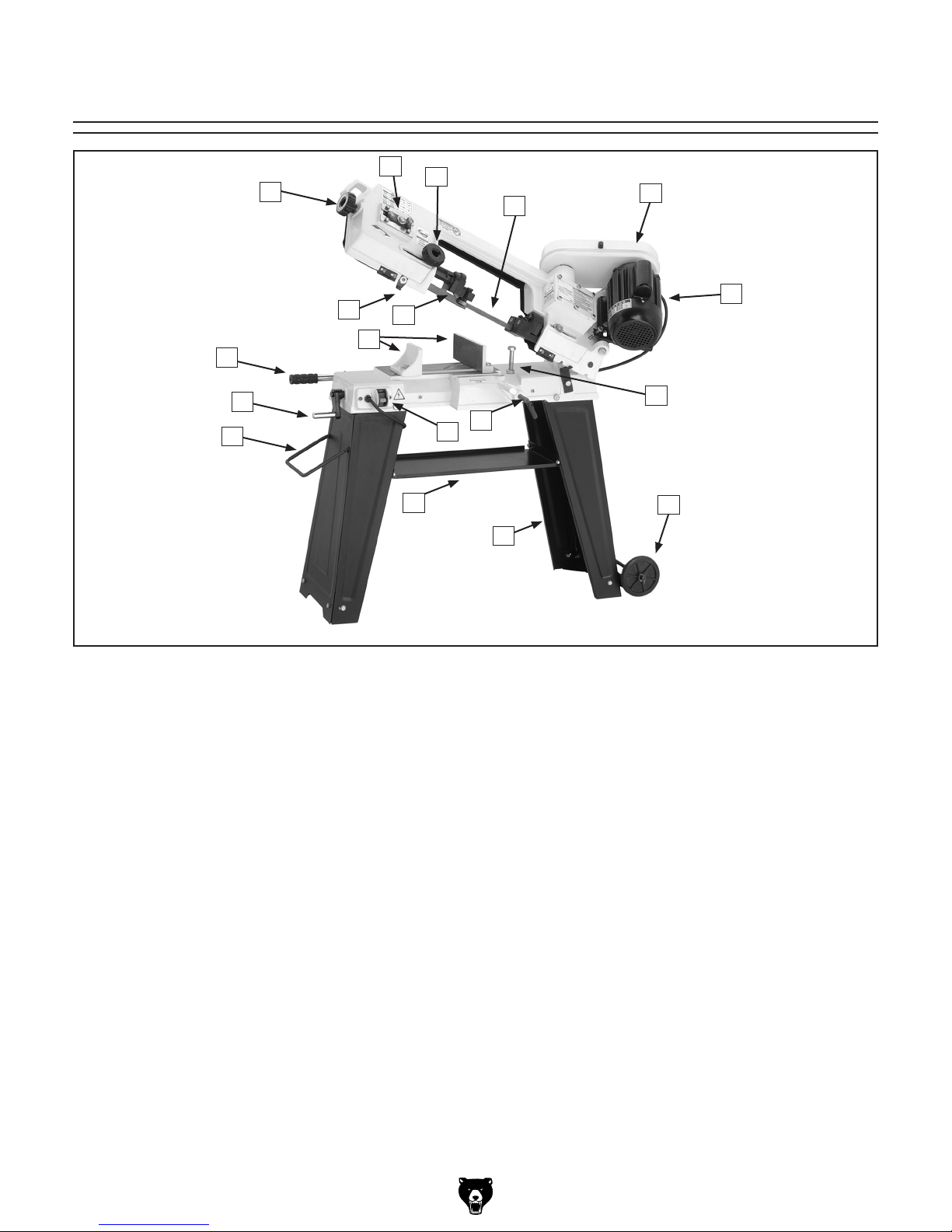
Identification ............................................................................................................................... 5
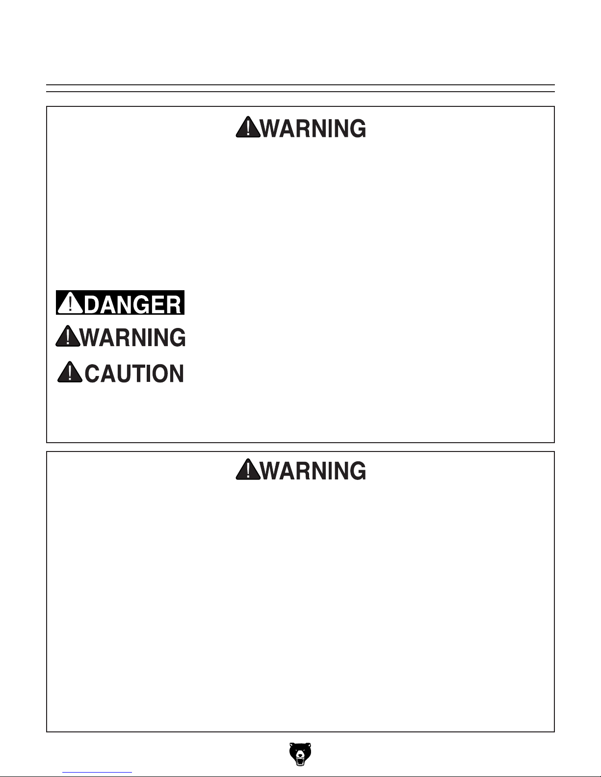
SECTION 1: SAFETY ....................................................................................................................... 6
Additional Safety Instructions for Metal Cutting Bandsaws ....................................................... 8
SECTION 2: CIRCUIT REQUIREMENTS ........................................................................................ 9
110V Operation .......................................................................................................................... 9
SECTION 3: SET UP ...................................................................................................................... 10
Set Up Safety ........................................................................................................................... 10
Items Needed for Set Up ......................................................................................................... 10
Unpacking ................................................................................................................................ 10
Inventory ................................................................................................................................... 11
Hardware Recognition Chart .................................................................................................... 12
Clean Up .................................................................................................................................. 13
Site Considerations .................................................................................................................. 13
Stand Assembly ....................................................................................................................... 14
Installing Pulleys ...................................................................................................................... 15
Installing V-Belt ........................................................................................................................ 16
Installing Work Stop ................................................................................................................. 17
Vertical Assembly ..................................................................................................................... 17
Test Run ................................................................................................................................... 19
Recommended Adjustments .................................................................................................... 19
SECTION 4: OPERATIONS ........................................................................................................... 20
Operation Safety ...................................................................................................................... 20
Vise .......................................................................................................................................... 20
Blade Speed ............................................................................................................................. 21
Blade Selection ........................................................................................................................ 22
Blade Guides ............................................................................................................................ 23
Feed Rate ................................................................................................................................ 23
Operation Tips .......................................................................................................................... 24
SECTION 5: ACCESSORIES ......................................................................................................... 25
SECTION 6: MAINTENANCE ........................................................................................................ 27
Schedule .................................................................................................................................. 27
Cleaning ................................................................................................................................... 27
Lubrication ................................................................................................................................ 27
SECTION 7: SERVICE ................................................................................................................... 28
Troubleshooting ........................................................................................................................ 28
Blade Change .......................................................................................................................... 30
Blade Tracking ......................................................................................................................... 31
Blade Tension .......................................................................................................................... 32
Squaring the Blade ................................................................................................................... 32
Blade Guide Bearings .............................................................................................................. 33
Electrical Components ............................................................................................................. 34
Wiring Diagram ........................................................................................................................ 34
Parts Breakdown ...................................................................................................................... 35
Parts List .................................................................................................................................. 36
Parts List .................................................................................................................................. 37
WARRANTY AND RETURNS ........................................................................................................ 38

-2- G0622 4" X 6" Metal Cutting Bandsaw
If you have any comments regarding this manual,
please write to us at the address below:
Grizzly Industrial, Inc.
C/O Technical Documentation Manager
P.O. Box 2069
Bellingham, WA 98227-2069
We stand behind our machines. If you have any
service questions or parts requests, please call or
write us at the location listed below.
Grizzly Industrial, Inc.
1203 Lycoming Mall Circle
Muncy, PA 17756
Phone: (570) 546-9663
Fax: (800) 438-5901
E-Mail: [email protected]
Web Site: http://www.grizzly.com
Foreword
INTRODUCTION
Contact Info
We are proud to offer the Model G0622 4" X 6"
Metal Cutting Bandsaw. This machine is part
of a growing Grizzly family of fine metalworking
machinery. When used according to the guide-
lines set forth in this manual, you can expect
years of trouble-free, enjoyable operation and
proof of Grizzly’s commitment to customer satis-
faction.
We are pleased to provide this manual with the
Model G0622. It was written to guide you through
assembly, review safety considerations, and cover
general operating procedures.
The specifications, drawings, and photographs
illustrated in this manual represent the Model
G0622 as supplied when the manual was pre-
pared. For your convenience, we always keep cur-
rent Grizzly manuals available on our website at
www.grizzly.com. Any updates to your machine
will be reflected in these manuals as soon as they
are complete.

G0622 4" X 6" Metal Cutting Bandsaw -3-
MODEL G0622 4" X 6" METAL CUTTING BANDSAW
Customer Service #: (570) 546-9663 • To Order Call: (800) 523-4777 • Fax #: (800) 438-5901
MACHINE DATA
SHEET
Product Dimensions:
Weight .............................................................................................................................................................144 lbs.
Length/Width/Height .......................................................................................................................... 16 x 39 x 19 in.
Foot Print (Length/Width) ................................................................................................................ 13-3/4 x 19-3/4 in.
Shipping Dimensions:
Type ............................................................................................................................................................ Cardboard
Content ............................................................................................................................................................Machine
Weight ..............................................................................................................................................................148 lbs.
Length/Width/Height ................................................................................................................ 17-3/4 x 21-1/2 x 37 in.
Electrical:
Switch .............................................................................................................................................Automatic Shut-Off
Switch Voltage .....................................................................................................................................................110V
Cord Length ..................................................................................................................................................... 8-1/2 ft.
Cord Gauge .................................................................................................................................................. 16 gauge
Recommended Breaker Size ........................................................................................................................... 15 amp
Plug ........................................................................................................................................................................ Yes
Motors:
Main
Type..................................................................................................................TEFC Capacitor Start Induction
Horsepower ............................................................................................................................................. 3/4 HP
Voltage.......................................................................................................................................................110V
Prewired .....................................................................................................................................................110V
Phase ....................................................................................................................................................... Single
Amps ..............................................................................................................................................................5A
Speed ................................................................................................................................................ 1725 RPM
Cycle .........................................................................................................................................................60 Hz
Number Of Speeds .......................................................................................................................................... 1
Power Transfer .................................................................................................................. V-Belt & Gear Drive
Bearings ...................................................................................................................... Shielded and Lubricated
Main Specifications:
Operation Information
Blade Speeds ........................................................................................................................ 78, 108, 180 FPM
Standard Blade Length ................................................................................................. 1/2 x 0.028 x 64-1/2 in.

-4- G0622 4" X 6" Metal Cutting Bandsaw
Cutting Capacities
Angle Cuts ................................................................................................................................................0-60°.
Vise Jaw Depth ..................................................................................................................................... 6-1/2 in.
Vise Jaw Height .................................................................................................................................... 3-1/4 in.
Max. Capacity Rectangle Height at 90° ...................................................................................................... 6 in.
Max. Capacity Rectangle Width at 90° ....................................................................................................... 6 in.
Max. Capacity Round at 90° ....................................................................................................................... 6 in.
Max. Capacity Rectangle Height at 45° ................................................................................................ 4-1/2 in.
Max. Capacity Rectangle Width at 45° ....................................................................................................... 4 in.
Max. Capacity Round at 45° ................................................................................................................. 4-1/2 in.
Max. Capacity Rectangle Height at 60° ................................................................................................ 2-1/2 in.
Max. Capacity Rectangle Width at 60° ................................................................................................. 2-1/2 in.
Max. Capacity Round at 60° ................................................................................................................. 2-1/2 in.
Construction
Table Construction ...............................................................................................................................Cast Iron
Stand Construction ................................................................................................................Pre-Formed Steel
Body Construction ..................................................................................................................... Aluminium Cast
Wheel Construction ..............................................................................................................................Cast Iron
Base Construction ................................................................................................................................Cast Iron
Paint. ..............................................................................................................................Urethane Hammertone
Other
Wheel Size ............................................................................................................................................ 7-3/8 in.
Blade Guides Upper ........................................................................................................................Ball Bearing
Blade Guides Lower ........................................................................................................................Ball Bearing
Table Information
Table Length ....................................................................................................................................... 10-1/4 in.
Table Width ........................................................................................................................................... 6-3/4 in.
Table Thickness .................................................................................................................................... 1-1/4 in.
Floor To Table Height ............................................................................................................................... 33 in.
Other Specifications:
Country Of Origin ................................................................................................................................................ China
Warranty .............................................................................................................................................................1 Year
Serial Number Location ..................................................................................................................ID on Body Frame
Assembly Time ...........................................................................................................................................25 minutes
Features:
Horizontal and Vertical Operation
Automatic Shut-Off
3/4 HP Motor
Work Stop

G0622 4" X 6" Metal Cutting Bandsaw -5-
Figure 1. Model G0622 controls and features.
A. Motor
B. Pulley Cover
C. Blade
D. Blade Guard Adjustment Knob
E. Blade Tracking Mechanism
F. Blade Tension Knob
G. Auto Off Tab
H. Blade Guide Bearing Assemblies
I. Feed Adjustment Handle
J. Vise Crank
K. Stand Handle
L. Power Switch
M. Vise Jaws
N. Tool Tray
O. Stand Wheels
P. Stand
Q. Work Stop
R. Horizontal Stop
Identification
A
M
F
I
J
K
GH
ED
CB
O
P
N
LQ
R

-6- G0622 4" X 6" Metal Cutting Bandsaw
SECTION 1: SAFETY

G0622 4" X 6" Metal Cutting Bandsaw -7-

-8- G0622 4" X 6" Metal Cutting Bandsaw
Additional Safety Instructions for Metal
Cutting Bandsaws
8. ATTENTION TO WORK AREA. Never
leave a machine running and unattended.
Pay attention to the actions of others in the
area to avoid unintended accidents.
9. MAINTENANCE/SERVICE. All inspec-
tions, adjustments, and maintenance are
to be done with the machine OFF and the
power disconnected to the machine. Wait
for all moving parts to come to a complete
stop.
10. HEARING PROTECTION & HAZARDS.
Noise generated by blade and workpiece
vibration, material handling, and power
transmission can cause permanent hear-
ing loss over time and interfere with com-
munication and audible signals. Always
wear hearing protection.
11. HOT SURFACES. Due to friction, the
workpiece, chips, and some machine com-
ponents can be hot enough to burn you.
12. STARTING POSITION. Never turn the
saw ON with the blade resting on the
workpiece.
13. EXPERIENCING DIFFICULTIES. If at
any time you are experiencing difficulties
performing the intended operation, stop
using the machine! Contact our Technical
Support Department at (570) 546-9663.
1. BLADE CONDITION. Do not operate with
dull, cracked or badly worn blade. Inspect
blades for cracks and missing teeth before
each use.
2. HAND PLACEMENT. Never position fin-
gers or thumbs in line with the cut. Hands
could be crushed in vise or by falling
machine components or cut by the blade.
3. ENTANGLEMENT HAZARDS. Do not
operate this bandsaw without blade guard
in place. Otherwise, loose clothing, jewelry,
long hair and work gloves can be drawn
into working parts.
4. BLADE REPLACEMENT. When replacing
blades, make sure teeth face toward the
workpiece. Wear gloves to protect hands
and safety glasses to protect eyes.
5. WORKPIECE HANDLING. Always sup-
port the workpiece with table, vise, or other
support fixture. Flag long pieces to avoid a
tripping hazard. Never hold the workpiece
with your hands during a cut.
6. LOSS OF STABILITY. Unsupported
workpieces may jeopardize machine sta-
bility and cause the machine to tip and fall,
which could cause serious injury.
7. POWER INTERRUPTION. Unplug machine
after power interruption. Machines without
magnetic switches can start up after power
is restored.
No list of safety guidelines can be complete. Every shop environment is different. Like all
machines there is danger associated with the Model G0622. Accidents are frequently caused by
lack of familiarity or failure to pay attention. Use this machine with respect and caution to lessen
the possibility of operator injury. If normal safety precautions are overlooked or ignored, serious
personal injury may occur.

G0622 4" X 6" Metal Cutting Bandsaw -9-
Figure 2. Typical type 5-15 plug and receptacle.
Serious personal injury could occur if you
connect the machine to the power source
before you have completed the set up pro-
cess. DO NOT connect the machine to the
power source until instructed to do so.
110V Operation
Amperage Draw
The Model G0622 motor draws the following
amps under maximum load:
Motor Draw .............................................. 5 Amps
Circuit Recommendations
We recommend using a dedicated circuit for this
machine. You MUST connect your machine to a
grounded circuit that is rated for the amperage
given below. Never replace a circuit breaker on
an existing circuit with one of higher amper-
age without consulting a qualified electrician to
ensure compliance with wiring codes. If you are
unsure about the wiring codes in your area or
you plan to connect your machine to a shared
circuit, consult a qualified electrician.
110V Circuit ...........................................15 Amps
Plug/Receptacle Type
Included Plug Type ........................... NEMA 5-15
This machine must have a ground prong in
the plug to help ensure that it is grounded.
DO NOT remove ground prong from plug
to fit into a two-pronged outlet! If the plug
will not fit the outlet, have the proper outlet
installed by a qualified electrician.
Extension Cords
We do not recommend the use of extension
cords, but if you find it absolutely necessary:
• Use at least a 16 gauge cord that does not
exceed 50 feet in length!
• The extension cord must also contain a
ground wire and plug pin.
• A qualified electrician MUST size cords over
50 feet long to prevent motor damage.
SECTION 2: CIRCUIT REQUIREMENTS
Electrocution or fire could
result if this machine is
not grounded correctly or
if your electrical configu-
ration does not comply
with local and state codes.
Ensure compliance by
checking with a qualified
electrician!

-10- G0622 4" X 6" Metal Cutting Bandsaw
The Model G0622 was carefully packed when it
left our warehouse. If you discover the machine
is damaged after you have signed for delivery,
please immediately call Customer Service at
(570) 546-9663 for advice.
Save the containers and all packing materials for
possible inspection by the carrier or its agent.
Otherwise, filing a freight claim can be difficult.
When you are completely satisfied with the con-
dition of your shipment, you should inventory the
contents.
Wear safety glasses dur-
ing the entire set up pro-
cess!
This machine presents
serious injury hazards
to untrained users. Read
through this entire manu-
al to become familiar with
the controls and opera-
tions before starting the
machine!
Unpacking
Set Up Safety
SECTION 3: SET UP
The Model G0622 is a
heavy machine. DO NOT
over-exert yourself while
unpacking or moving
your machine—get assis-
tance.
The following items are needed to complete the
set up process, but are not included with your
machine:
Description Qty
• Safety Glasses (for each person) .............. 1
• 12mm Open End Wrench ........................... 1
• 14mm Open End Wrench ........................... 1
• Sawhorses .................................................. 2
• Helper for Lifting ......................................... 1
• Cleaning Supplies ...................................... 1
• Pliers .......................................................... 1
• Phillips Head Screwdriver #2 ..................... 1
• Straightedge, 12" Minimum ........................ 1
Items Needed for
Set Up

G0622 4" X 6" Metal Cutting Bandsaw -11-
Inventory
After all the parts have been removed from the
two boxes, you should have the following items:
Box 1: (Figure 3) Qty
A. Bandsaw (not shown) ................................. 1
B. Stand Legs ................................................. 2
C. Tool Tray .................................................... 1
D. Corner Support Braces .............................. 4
E. Wheels ....................................................... 2
F. Axle ............................................................ 1
G. Wheel Mounting Bracket ............................ 1
H. Work Stop Rod ........................................... 1
I. Work Stop ................................................... 1
J. Transport Handle ........................................ 1
K. Pulley Cover ............................................... 1
L. V-Belt .......................................................... 1
M. Pulleys w Keys ........................................... 2
N. Table .......................................................... 1
O. Table Support ............................................. 1
Hardware Bag (not shown)
• Hex Wrench 4mm (Work Stop) .................. 1
• Hex Bolt M8-1.25 x 20 (Saw to Stand) ...... 6
• Hex Nut M8-1.25 (Saw to Stand) ............... 6
• Flat Washer 8mm (Saw to Stand) .............. 6
• Lock Washer 8mm (Saw to Stand) ............ 6
• Hex Bolt M6-1 x 12 (Stand) ........................ 8
• Phillips Head Screw M6-1 x 12 (Tray) ....... 4
• Hex Nut M6-1 (Stand, Tray, Table) .......... 13
• Flat Washer 6mm (Stand, Tray) ............... 12
• Fender Washer 6mm (Table) ..................... 1
• Flat Head Screw M6-1 x 10 (Table) ........... 1
• Cotter Pins (Axle & Handle) ....................... 4
Figure 3. Model G0622 Inventory.
In the event that any nonproprietary parts are
missing (e.g. a nut or a washer), we would be
glad to replace them, or for the sake of expedi-
ency, replacements can be obtained at your local
hardware store.
NOTICE
Some hardware/fasteners on the inventory
list may arrive pre-installed on the machine.
Check these locations before assuming that
any items from the inventory list are miss-
ing.
BC
D
E
F
G
H
I
J
K
LM
N
O
SUFFOCATION HAZARD!
Immediately discard all plas-
tic bags and packing materi-
als to eliminate choking/suf-
focation hazards for children
and animals.

-12- G0622 4" X 6" Metal Cutting Bandsaw
Hardware Recognition Chart

G0622 4" X 6" Metal Cutting Bandsaw -13-
Figure 4. Minimum working clearances.
Floor Load
Refer to the Machine Data Sheet for the weight
and footprint specifications of your machine.
Some floors may require additional reinforcement
to support both the machine and operator.
Placement Location
Consider existing and anticipated needs, size of
material to be processed through each machine,
and space for auxiliary stands, work tables or
other machinery when establishing a location for
your new machine. See Figure 4 for the minimum
working clearances.
Unsupervised children and
visitors inside your shop
could cause serious per-
sonal injury to themselves.
Lock all entrances to the
shop when you are away and
DO NOT allow unsupervised
children or visitors in your
shop at any time!
The unpainted surfaces are coated with a waxy
oil to protect them from corrosion during ship-
ment. Remove this protective coating with a sol-
vent cleaner or citrus-based degreaser such as
Grizzly’s G7895 Degreaser. To clean thoroughly,
some parts may need to be removed. For opti-
mum performance from your machine, make
sure you clean all moving parts or sliding
contact surfaces that are coated. Avoid chlo-
rine-based solvents, such as acetone or brake
parts cleaner, as they may damage painted sur-
faces should they come in contact. Always follow
the manufacturer’s instructions when using any
type of cleaning product.
Site ConsiderationsClean Up
Gasoline and petroleum
products have low flash
points and could cause
an explosion or fire if
used to clean machinery.
DO NOT use gasoline or
petroleum products to
clean the machinery.
Many of the solvents
commonly used to clean
machinery can be toxic
when inhaled or ingest-
ed. Lack of ventilation
while using these sol-
vents could cause seri-
ous personal health risks
or fire. Take precautions
from this hazard by only
using cleaning solvents
in a well ventilated area.

-14- G0622 4" X 6" Metal Cutting Bandsaw
Stand Assembly
Components and Hardware Needed: Qty
Bandsaw .............................................................1
Hex Bolts M6-1 x 12 ...........................................8
Flat Washer 6mm .............................................12
Hex Nuts M6-1 .................................................12
Stand Legs .........................................................2
Corner Support Braces ......................................4
Axle ....................................................................1
Wheels ................................................................2
Cotter Pins ..........................................................4
Transport Handle ................................................1
Wheel Mounting Bracket ....................................1
Hex Bolts M8-1.25 x 20 ......................................6
Hex Nuts M8-1.25 .............................................6
Flat Washers 8mm ............................................6
Tool Tray .............................................................1
Phllips Head Screws M6-1 x 12 .........................4
To assemble the stand:
1. Unfold the two stand leg assemblies. They
are hinged on the edges for easy set up.
2. Using the M6-1 hex nuts, hex bolts and flat
washers, install the corner support braces
in the bottom corners of the leg assemblies
(Figure 5).
3. On one of the leg assemblies, attach the
wheel mounting bracket along with the cor-
ner support braces to the outside bottom
edge as shown in Figure 5.
6. On the other leg, Insert the handle into the
pre-drilled holes and secure with the cotter
pins (see Figure 7).
Figure 5. Corner braces and wheel bracket.
Wheel Mounting
Bracket
Corner Support
Braces
Figure 7. Cotter pins installed into
the handle.
Figure 6. Wheel assembly.
Cotter Pin
4. Slide the axle through the holes in the mount-
ing bracket on the bottom edge of the stand.
5. Slide the wheels onto the axle on the outside
of the mounting brackets, and secure with the
cotter pins as shown in Figure 6.
Cotter Pin

G0622 4" X 6" Metal Cutting Bandsaw -15-
Installing Pulleys
The V-belt drive system for the bandsaw requires
the installation of two pulleys. The pulleys are
covered for operator safety and to keep the V-belt
and pulleys clean.
Components and Hardware Needed: Qty
Pulley Cover ...................................................... 1
Pulleys & Keys ................................................... 2
Phillips Head Screws M6-1 x 25 (installed) ....... 2
Flat Washers 6mm (installed) ............................ 2
To install the pulley cover:
1. KEEP BANDSAW UNPLUGGED!
2. Place the pulley cover over the motor and
gear shafts, and secure with the (already
installed) M6-1 x 12 Phillips head screws and
flat washers as shown in Figure 10.
7. With the help of an assistant, lift the bandsaw
onto a pair of closely spaced sawhorses or
other suitable support (see Figure 8).
Figure 9. Tool tray.
Figure 8. Leg assembly.
8. Attach the legs to the bandsaw with the M8-
1.25 x 20 hex bolts, flat washers, and hex
nuts.
Note: At this time, tighten with a 14mm
wrench or socket just enough to secure the
parts. Final tightening will take place when
the stand is fully assembled.
9. Remove the sawhorses and install the tool
tray in the middle of the stand as shown in
Figure 9 with M6-1 Phillips head screws, flat
washers and hex nuts.
10. Check to see if the bandsaw is relatively level
then final tighten all the nuts.
Figure 10. Installing pulley cover.

-16- G0622 4" X 6" Metal Cutting Bandsaw
To install the pulleys:
1. Open pulley cover.
2. Insert the woodruff keys into the slots on the
shafts.
3. Slide the large diameter motor pulley onto
the motor shaft, closest (Figure 11).
Figure 11. Installing motor pulley.
Figure 12. Checking pulley alignment.
3. Install the worm gear pulley with the small
diameter wheel closest to the gear box.
4. Use a straightedge to check the alignment of
the pulley wheels as shown in Figure 12.
Motor Pulley
with Key Slot
5. When the pulley wheels are aligned, tighten
the setscrews on both pulleys.
To install the V-belt around the pulleys:
1. KEEP BANDSAW UNPLUGGED!
2. Unthread the motor lock bolt to allow the
motor to pivot up.
3. Open the pulley cover door and pivot the
motor up to allow the V-belt to slide into the
pulley grooves as shown in Figure 13.
Figure 13. V-belt installation.
Installing V-Belt
4. Release the motor, letting the weight tension
the V-belt, and thread the motor lock bolt
against the side of the bandsaw.
Motor Lock
Bolt

G0622 4" X 6" Metal Cutting Bandsaw -17-
Installing Work Stop
The work stop is designed to provide the operator
a quick reference for making multiple cuts at the
same length.
To install the work stop onto the bandsaw:
1. KEEP BANDSAW UNPLUGGED!
2. Install the work stop shaft into the side of the
bandsaw then lock it in place by tightening
the setscrew (see Figure 14).
3. Slide the work stop onto the end of the shaft
and lock it into position with the locking lever
shown in Figure 15.
Figure 14. Installing work stop shaft.
Figure 15. Work stop locking lever.
Locking Lever
Vertical Assembly
The Model G0622 can easily be set up for vertical
cutting operations.
Components and Hardware Needed: Qty
Table ...................................................................1
Table Bracket .....................................................1
Flat Head Screw 1⁄4"-20 x 1⁄2" ..............................1
Switch Safety Bracket ........................................1
Hex Nut 1⁄4"-20 ....................................................1
To assemble the bandsaw for vertical cut-
ting:
1. Remove the two flat head screws and the
blade guide cover shown in Figure 16.
2. Install the table and replace the two screws
removed in Step 1.
3. Install the table bracket shown in Figure 17
with the bolt (already in the casting), the flat
head screw, and the hex nut.
Figure 16. Blade guide cover.
Blade Guide Cover
Figure 17. Table and bracket installed.
Bolt Already
in Casting

-18- G0622 4" X 6" Metal Cutting Bandsaw
Figure 19. Adjustment bolt.
Figure 18. Adjusting table level.
Figure 20. Safety bracket.
5. Place a level on the table, as shown in Figure
18, and adjust the adjustment bolt shown in
Figure 19 until the table is level.
6. Install the safety bracket and lock in place
with the pin shown in Figure 20 to keep the
saw from falling.
Note: To ensure the safety bracket fits
securely in the notch on the body frame, the
safety bracket may need to be slightly "modi-
fied" with a hammer or other appropriate
implement to fit securely.
Safety Bracket
Pin
Other manuals for G0622
3
Table of contents
Other Grizzly Saw manuals

Grizzly
Grizzly G0561 User manual

Grizzly
Grizzly G0700 User manual

Grizzly
Grizzly G0659 User manual

Grizzly
Grizzly T31634 User manual

Grizzly
Grizzly G0623X Instruction Manual

Grizzly
Grizzly G5045 User manual

Grizzly
Grizzly G1073 User manual

Grizzly
Grizzly G0605X1-6X1 User manual

Grizzly
Grizzly G1023RLX User manual

Grizzly
Grizzly G0622 User manual

Grizzly
Grizzly G0962A40 User manual

Grizzly
Grizzly G0580 Quick start guide

Grizzly
Grizzly G1538 User manual

Grizzly
Grizzly G9743 User manual

Grizzly
Grizzly H6246 Quick start guide

Grizzly
Grizzly G0478 User manual

Grizzly
Grizzly G0504 User manual

Grizzly
Grizzly G1011Z User manual

Grizzly
Grizzly G0681 User manual

Grizzly
Grizzly G0524 User manual