manuals.online logo
Brands
  1. Home
  2. •
  3. Brands
  4. •
  5. Grizzly
  6. •
  7. Storage
  8. •
  9. Grizzly Conwood Wood Display User manual

Grizzly Conwood Wood Display User manual

Conwood Wood Display - Basic
ASSEMBLY INSTRUCTIONS
Before you begin:
Check the contents to make sure the following items
came with your kit:
L eft H S ide
(1 ea.)
R ight H S ide
(1 ea.)
B ac k
(2 ea.)
H-C hannel
(1 ea.)
G raphic
E nd
(2 ea.)
B as e S helf
(1 ea.)
S helf
(2 ea.)
Header B as e
(1 ea.)
Top
(1 ea.)
T ag C hannel
(4 ea.)
Toe K ic k
(1 ea.)
Header
(1 ea.)
R ight H B as e
Angle
(1 ea.)
L eft H B as e
Angle
34mm
C onnec ting
B olt
(8 ea.)
8mm
C onnec ting
B olt
(16 ea.)
3/4" Wood S c rew
(13 ea.)
1/4-20 Hex Nut
(8 ea.)
1/4-20 x 3/4
C ros s -Head S c rew
(8 ea.)
1/2" Wood S c rew
(23 ea.)
C am
(8 ea.)
C as ter
(2 ea.)
W hite P las tic C am
(16 ea.)
Top S helf
(1 ea.)
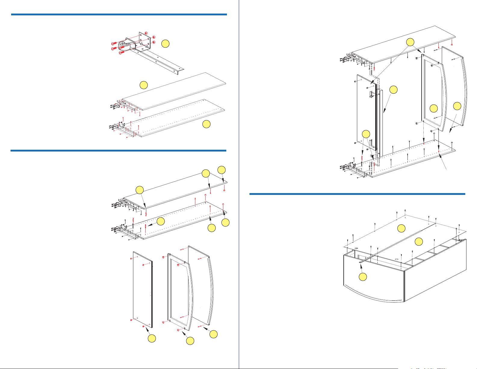
Section 1: Install Casters and Base Angles
Section 2: Attach Top and Sides
Section 3: Attach Back Panel
a. Install a C as ter onto each of the two
B as e Angles using four 1/4-20 x 3/4"
Cross-head Screws and four 1/4-20
Hex Nuts for each.
b. Attach L eft B as e Angle to the bottom
of L eft H S ide using three 1/2" Wood
Screws on the side and three 3/4"
Wood Screws on the bottom.
c. Attach R ight B as e Angle to the
bottom of R ight H S ide using three
1/2" Wood S c rews on the side and
three 3/4" Wood S c rews on the
bottom.
a. Insert two Cams into holes at top of
R ight H S ide. Arrows on cams must
point to connecting holes at top edge.
Do the same on the L eft H S ide.
b. Screw two 8mm Connecting Bolts into
the 7th hole from the top on right and
left sides of R ight H S ide. Do the
same on L eft H S ide.
c. Screw two 34mm Connecting Bolts into
the bottom holes on right and left sides
of R ight H S ide. Do the same on L eft
H S ide.
d. Screw four 34mm Connecting Bolts
into the four holes on the bottom of
Top.
e. Insert four White Plastics Cams into
holes on bottom of Header B as e.
f. Screw four Cams into holes on bottom
of B as e S helf.
g. Place Header B as e over connectors
at top of R ight H S ide. Cams must be
facing towards the bottom and curved
edge facing the front of display. Turn
Cams fully clockwise to attach.
h. Place B as e S helf on bottom 34mm
Connectors on R ight H S ide. Cams in
Base Shelf must be facing towards
bottom of display. Turn Plastic Cams
on B as e S helf fully clockwise to
attach.
i. Lower L eft H S ide onto B as e S helf
and Header B as e and attach in the
same manner.
j. Attach Top by inserting Connecting
Boltsinto holes on the top of L eft H
S ide and R ight H S ide. Make sure
Top and S ides fit securely. Turn Cams
in each S ide to attach Top.
k. Attach Toe K ick to bottom front of the
display with six 1/2" Wood Screws on
the sides and two 3/4" Wood Screws
on the bottom.
Carefully turn Display unit over onto its
face.
a. Place B ac k P anels on unit with large
holes facing top of unit.
b. Insert H-channel between Back
Panels pressing each Panel into
grooves in the H-channel.
c. Align B ac k P anels with holes on back
of Display unit and attach using 3/4"
Wood Screws (14).
Left H Side
Right H Side
Left
H Side
Right
H Side
a
b
c
Header Base
Located Here
(Hole 7)
a
a
b
b
c
c
Header Base
Located Here
(Hole 7)
k
h
j
g
Lay L eft H S ide and R ight H S ide adjacent
to each other with holes pointing upward.
e
d
f
Top
Header
Base
Base
Shelf
Top
Header
Base
Base
Shelf
i
a
a
b
32
Section 4: Install Shelves
Section 5: Finishing
Carefully turn Display over onto its back.
a. Insert four White Plastic Cams into
holes on bottom of Top S helf and
remaining S helves .
b. Screw four 8mm Connecting Bolts at
desired Shelf levels for each Shelf,
two Connecting Bolts each side.
c. Place each S helf over Connecting
Bolts (Cams must face bottom of
Display). Attach each by turning Cam
fully clockwise. (Top S helf will be the
one placed under Header B as e).
Carefully stand display up.
a. Install Tag C hannel to front of each Shelf by
placing tab on back of C hannel into groove on
front of Shelf. Press Tag C hannels firmly in
place.
b. Install L ight onto bottom of Top using two
1/2" Wood Screws. It may be necessary to
remove the cover on the light to gain access to
the L ight's mounting holes.
c. Attach G raphic E nd to each side of Display unit
between Top and Header B as e with two
1/2" Wood Screws for each.
d. Place Header G raphic B anner by inserting it
through Top slot behind Graphic Ends into
groove on Header B as e.
e. Adjust Levelers on bottom of Toe Kick to level
Display unit.
a
b
a
c
e
b
d
Display Source Info
2005 Copyright Notice

Other Grizzly Storage manuals

Grizzly H8140 User manual

Grizzly

Grizzly H8140 User manual

Grizzly T26898 User manual

Grizzly

Grizzly T26898 User manual

Grizzly H8140 User manual

Grizzly

Grizzly H8140 User manual

Popular Storage manuals by other brands

Alpha ESS SMILE5 AU Installation, operation & maintenance manual

Alpha ESS

Alpha ESS SMILE5 AU Installation, operation & maintenance manual

Promise Pegasus2 R4 quick start guide

Promise

Promise Pegasus2 R4 quick start guide

Contec PC-SDD32V3-SC user guide

Contec

Contec PC-SDD32V3-SC user guide

Black Box NBC26S-R2 manual

Black Box

Black Box NBC26S-R2 manual

ORi NS200RC3 user manual

ORi

ORi NS200RC3 user manual

Promise Apollo user guide

Promise

Promise Apollo user guide

Qlogic iSR6200 quick start guide

Qlogic

Qlogic iSR6200 quick start guide

VST FireWire user guide

VST

VST FireWire user guide

HP Surestore 6164 - Switch user guide

HP

HP Surestore 6164 - Switch user guide

Netstor NA381TB Quick installation guide

Netstor

Netstor NA381TB Quick installation guide

Sony CSM200B installation manual

Sony

Sony CSM200B installation manual

Spectra T200 user guide

Spectra

Spectra T200 user guide

Freecom LTO OEM HH datasheet

Freecom

Freecom LTO OEM HH datasheet

VERITAS Access 3340 Hardware Service Procedure

VERITAS

VERITAS Access 3340 Hardware Service Procedure

Sony AIT-SDX550 Product specifications manual

Sony

Sony AIT-SDX550 Product specifications manual

Maxtor SATAII/300 INTERNAL HARD DRIVE installation guide

Maxtor

Maxtor SATAII/300 INTERNAL HARD DRIVE installation guide

Fujitsu ETERNUS AX Series Installation and cabling guide

Fujitsu

Fujitsu ETERNUS AX Series Installation and cabling guide

Imation Apollo Expert 1.5TB Specifications

Imation

Imation Apollo Expert 1.5TB Specifications

manuals.online logo
manuals.online logoBrands
  • About & Mission
  • Contact us
  • Privacy Policy
  • Terms and Conditions

Copyright 2025 Manuals.Online. All Rights Reserved.