
8 OM-HY/6G
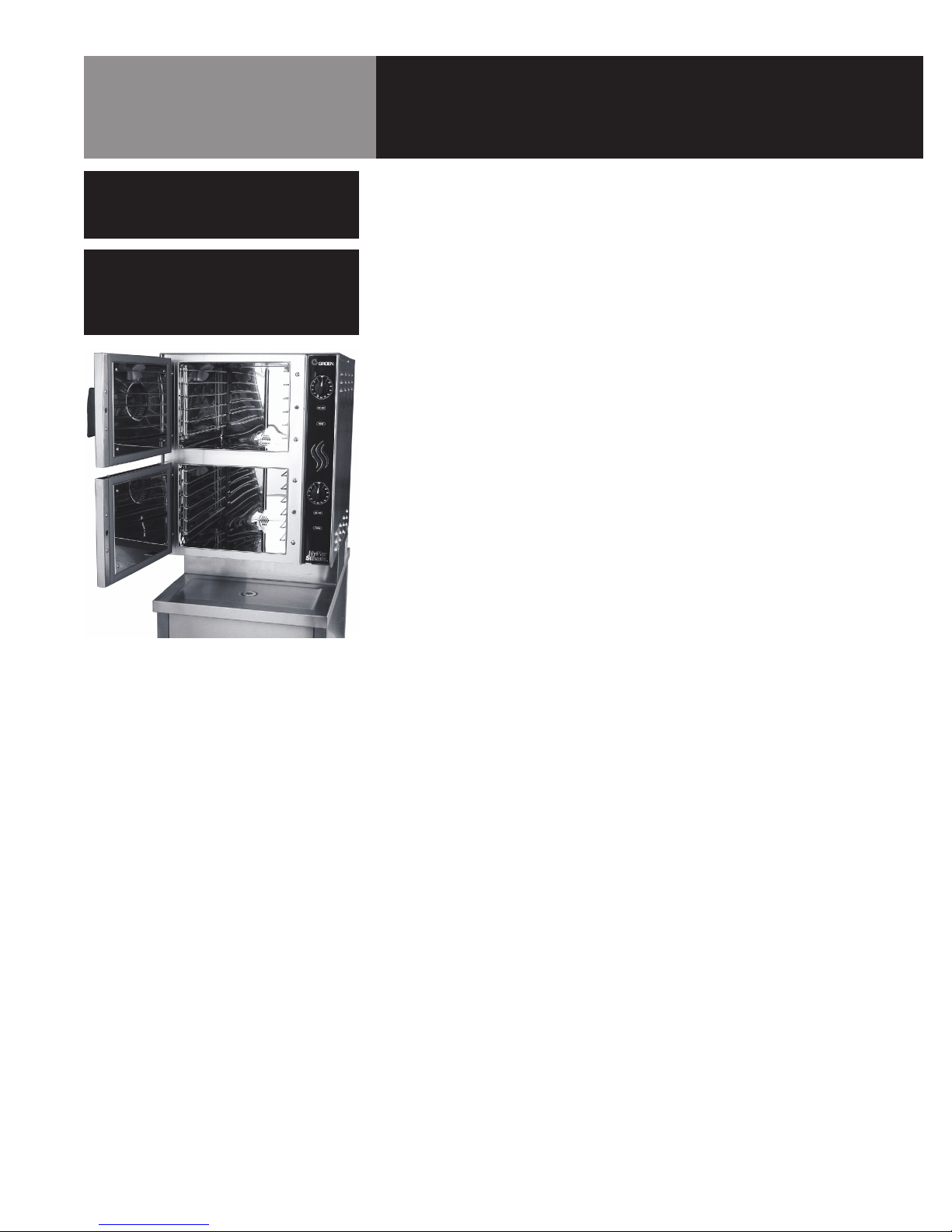
The HY-6G steamer is suitable for installation on or near both combustible and
noncombustible surfaces. Minimum installation clearances are:
Right Side 2 inches
Left Side 0 inches
Rear 6 inches
However, for easy service at least 12 inches clearance is required for the right side of
the unit, and it may not be installed within 12 inches of a heat source, as stated in the
Caution above.
The unit must be installed in a well-ventilated room with an adequate air supply. The
steamer must be installed beneath a ventilation hood, since gas combustion products
exit the appliance.
Any item which might obstruct or restrict the flow of air for combustion and ventilation
must be removed. Do not obstruct the flue cover or any front, side, rear, or top vents
after installation.
The area directly around the appliance must be cleared of all combustible material.
The installation must conform with local codes or, in the absence of local codes, with
the National Fuel Gas Code, ANSI Z223.1, latest edition, including the following:
The unit and its individual shutoff valve must be disconnected from the gas supply
system during any pressure testing of that system at test pressures in excess of 1/2
PSI (3.45 kPa). It must be isolated from the gas supply piping system by closing its
individual manual shutoff valve during any pressure testing of the gas supply piping
system at test pressures equal to or less than 1/2 PSI (3.45 kPa).
1. Electrical Supply Connection
Provide 115 VAC, 60 HZ, 1 PH, 15 AMP service. Bring conduit in through open
frame on the under-side of cabinet. Local codes and/or the National Electrical
Code should be observed in accordance with ANSI/NFPA 70-1987 (or latest
edition). AN ELECTRICAL GROUND IS REQUIRED. The electrical schematic is
located in the service compartment and in this manual. Maximum load is 2
AMPs. In Canada, provide electrical service in accordance with the Canadian
Electrical Code, CSA C22.1 Part 1 and/or local codes.
2. Gas Supply Connection
Connection to the gas supply can be completed with 1/2” NPT pipe or approved
equivalent. Although the immediate connection to the appliance is “ NPT, gas
supply piping must be large enough to provide 90,000 BTU/hr. Supply pressure
must be at least 4.5” W.C. (maximum 14” W.C.) for natural gas or 12” W.C.
(maximum 14” W.C.) for LP gas. In Canada, the installation must conform to the
Canadian Gas Code, CAN 1-B149, Installation Codes for Gas Burning Appliances
and Equipment and/or local codes. After the unit has been connected to the gas
supply, all gas joints must be checked for leaks.
No flame should be used when checking for leaks. A thick soap solution or other
suitable leak detector should be used.
WARNING
THE UNIT MUST BE INSTALLED BY
PERSONNEL WHO ARE QUALIFIED TO WORK
WITH GAS, ELECTRICITY AND PLUMBING.
IMPROPER INSTALLATION CAN CAUSE
INJURY TO PERSONNEL AND/OR DAMAGE
TO THE EQUIPMENT. THE UNIT MUST BE
INSTALLED IN ACCORDANCE WITH
APPLICABLE CODES. THE UNIT MUST BE
INSTALLED BY A LICENSED PLUMBER OR
GAS FITTER WHEN INSTALLED WITHIN THE
COMMONWEALTH OF MASSACHUSETTS.
CAUTION
DO NOT INSTALL THE UNIT WITH THE RIGHT
SIDE VENTS BLOCKED OR WITHIN 12 INCHES
OF A HEAT SOURCE (LIKE A BRAISING PAN,
DEEP FRYER, CHAR BROILER, OR KETTLE).
TO AVOID DRAIN PROBLEMS, LEVEL THE
UNIT FRONT TO BACK, OR PITCH IT
SLIGHTLY TO THE REAR.
Installation
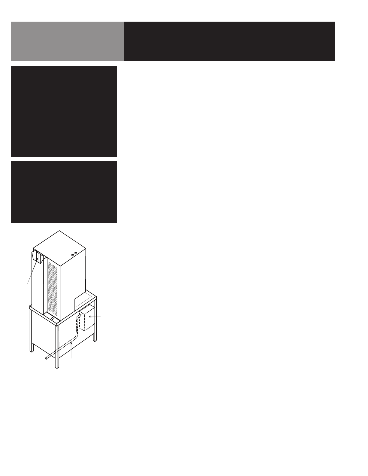
Flue
UNIT
REAR
Electrical
Conduit
Control
Box
UNIT
FRONT
The knockout hole is sized for a one inch
conduit fitting. Pass the wire up the back
through this knockout hole to the front. Make
the connections from the front.


HY-3E User manual")

 User manual")


