3
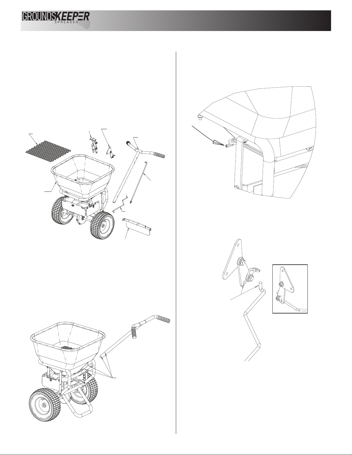
I. Set the Restrictor
Plate Fully Open and
the Control Handle to
"30" (as shown)
F. Attach Control Handle
Assembly to Frame
Using M6x40 Bolts
G. Remove Control
Handle from Assembly,
Insert Upper Linkage
into Control Handle,
Reattach Control Handle
H. Thread First Jam Nut
onto Upper Linkage and
Insert Linkage into Control
Plate Assembly
Secure Linkage with Second Jam Nut and Tighten
First Jam Nut
Step E
Attach Control Plate Assembly
To Frame Using M6x40 Bolts
This End Of Rod To
Be Facing Upward
J. Attach Rear Deflector
Using M6x20 Bolts
Rod To Be Flat (Parallel
To The Ground)
Fig. 5
Fig. 6
Fig. 7
Attach Control Handle Assembly, Upper Linkage,
& Rear Deflector – Figure 6 & 7
F. Mount the Control Handle Assembly to the Handle using two
M6x40 bolts as shown.
G. Insert the Upper Linkage into the Control Handle as shown.
H. Thread one Jam Nut so that the Restrictor Plate underneath the
Hopper is fully open when the Control Handle is at "30". Assemble
the second jam nut in this position to lock the linkage in place.
I. Verify that the Restrictor Plate may be fully closed by pushing
the Control Handle forward.
J. Using two M6x20 bolts, attach the rear deflector.
Final Assembly
A. Check And Tighten All Fasteners – Make sure the Gearbox
turns freely when pushing and pulling the unit.
B. Place the Screen in the hopper.
C. Install the Rain Cover on the hopper.
Operation
1. Before filling Hopper, ensure that the Restrictor Plate is fully
closed and the screen is in place.
2. Move and tighten the stop bolt to the desired setting.
3. Begin moving forward with the spreader.
4. Pull the Control Handle back to the stop bolt to open
Restrictor Plate and allow material to flow.
5. Before stopping, push the Control Handle forward to stop
the flow.
Maintenance
1. The Hopper and Spinner should be completely emptied and
cleaned before storage.
2. The Spreader should be washed and dried before storage.
3. Check that the Restrictor Plate and Linkage move freely. Clear
out any debris between the Restrictor Plate & the Hopper.
4. Check that the gearbox moves freely.
5. Check torque of all fasteners on a monthly basis.
Operation Notes
1. The spreader is designed to be operated at a brisk walking
pace (approx. 3mph). Walking slower or faster will alter the
distribution pattern & amount of the material, as will the moisture
content of the material & other environmental factors.
2. Grease should be applied to the gear box during seasonal
use, and prior to storing for the season.
WARNING
When filling hopper, make certain there are no large objects within the
material. Objects larger than the openings in the Screen may cause
the spreader to clog or even damage the drive system. Never leave
material in the hopper when not in use.
I. Set the Restrictor
Plate Fully Open and
the Control Handle to
"30" (as shown)
F. Attach Control Handle
Assembly to Frame
Using M6x40 Bolts
G. Remove Control
Handle from Assembly,
Insert Upper Linkage
into Control Handle,
Reattach Control Handle
H. Thread First Jam Nut
onto Upper Linkage and
Insert Linkage into Control
Plate Assembly
Secure Linkage with Second Jam Nut and Tighten
First Jam Nut
Step E
Attach Control Plate Assembly
To Frame Using M6x40 Bolts
This End Of Rod To
Be Facing Upward
J. Attach Rear Deflector
Using M6x20 Bolts
Rod To Be Flat (Parallel
To The Ground)