INTRODUCTION
A transistor ladder made with vintage transistors gives the same sonic
character to the GMS-294A Four Pole Low Pass filter recreation that the
original 904A Four Pole Low Pass filter possesses.
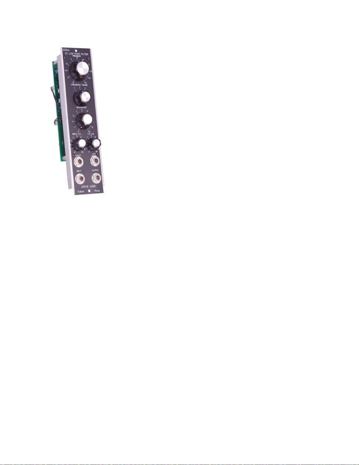
A rotary switch selects the frequency range and a panel fine tune
potentiometer allows setting the exact filter frequency. Gain controls are
provided for the audio input and the frequency voltage control inputs.
A resonance control on the panel will produce a variable peak at the filter
corner frequency. If the control is increased to within approximately 20 % of
the maximum, the filter will begin to oscillate with a fairly pure sine wave.
The frequency of the oscillation can be controlled by the 1V/Octave and the
exponential FM control voltage inputs.
The MU version is housed in a 1MU (2.125 inch wide by 8.75 inch high)
panel with DOTCOM compatible power connector.
The original 904a filter input amplitude before clipping was 7 Volts peak to peak. Incorporating an audio
attenuator on the input of the filter allows the accommodation of the somewhat higher signal levels found
in modern synthesizers without clipping the output waveform. It also permits overdriving the input when
that effect is desired.
The resonance control feeds back some of the output signal of the filter in phase with the input signal.
This causes a resonance peak to occur at the filter cutoff frequency. The resonance control on this filter,
as in the original, causes the signal below the cutoff frequency to be attenuated. While the peak value of
the signal rises somewhat, the overall effect of the resonance at the cutoff is enhanced by the reduction in
amplitude of other frequencies. This gives almost a bandpass effect at high resonances.