Grove Audio GMS-632 User manual

GMS-632 USB/MIDI/CV INTERFACE
PRELIMINARY OPERATION MANUAL
FEBRUARY22, 2018
Grove Audio LLC
Copyright 2018 –All Rights Reserved


INTRODUCTION
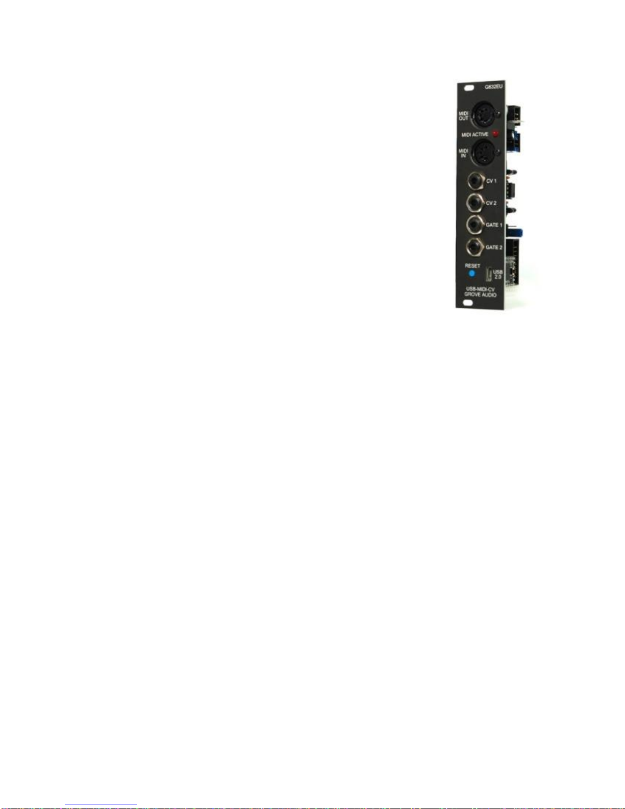
A Eurorack compatible USB MIDI to CV converter using the Teensy 3.1
microcontroller as its USB port and controller. The 6HP wide unit includes
2 CV channels, 2 gate channels, an isolated DIN MIDI input connector
and a DIN MIDI output connector.
When the module is sent from the factory, a simple operating sketch is
loaded that will permit the module to be recognized by an attached
computer as a USD MIDI device. MIDI note commands sent to the module
are echoed on the MIDI OUT DIN connector and valid MIDI note values
are converted to analog CV values on the CV output connectors. An
accompanying GATE signal is produced. When the MIDI note on value is
received the GATE output goes high (+5 VDC). When the MIDI note off
value is received, the GATE output goes low (O VDC).
When a valid MIDI note command is received on the MIDI IN DIN connector, it is converted to an analog
CV output value along with a accompanying GATE output. The MIDI note command is also sent to the
USB MIDI connector and to a connected computer. The MIDI IN DIN to analog CV output will operated
without an external computer connected so the module can be used as a standalone MIDI to CV
converter.
The source for the current factory installed program can be downloaded from the Grove Audio website.
Users with an Arduino IDE with Teensyduino extensions can customize this program to their own needs.
See appendix B for information regarding installing HEX image updates as well as instructions on how to
obtain and setup the Arduino development environment.
The control voltage output range is internally settable to 0-10 Volts or -5-+5 Volts. The gate signal is 0-5
Volts active-high. The software for the unit is open-source and can be reloaded and modified by the user.
A programming development environment that utilizes the Arduino IDE with a Teensy support add-in can
be used to create new functions using Arduino-like commands.
The Teensy 3.1 is a powerful microprocessor card containing a 72MHz Freescale MK20DX256 Cortex-
M4 processor and USB communications processor on a 3/4 inch by 1 1/3 inch PC board. It has 256KB of
program memory and 64KB of RAM. There is a Teensyduino add-in available for the Arduino IDE that
allow sketches developed in the Arduino enviroment to be loaded into the Teensy.

GMS-632 BLOCK DIAGRAM

INSTALLATION AND CONFIGURATION
The following picture shows the connectors and configurable jumpers on the GMS-632 board. Be sure to
connect the power cable only to the power connector. Connecting power to the expansion connector
could cause damage to the processor module. Set the 5V Power Source jumper before powering up the
board. This jumper determines where the card will get its +5V power from. One position derives the power
from the power bus. By setting the jumper to the other position, +5V power would come from an on-board
+5V power regulator. Using this method will result in a higher current draw from the +12V power bus.
SOFTWARE INSTALLATION AND UPDATES
Appendix B describes how toinstall the HalfKay bootloader software that allows installation of hex files
produced by the Arduino/Teensyduino integrated development environment. Initial and update
software files downloaded from the Grove Audio website use this bootloadersoftware for installation.

TECHNICAL SPECIFICATIONS
USB Device Interface
Supported as USB 2.0 class compliant device, additional supported endpoints
Analog outputs
Two analog outputs. Voltage input range is 0 - +10 Volts or +-5 Volts (jumper selectable).
Internal over and undervoltage protection.
Digital outputs
Two digital gate outputs are provided. Voltage output range is 0 - +5 Volts. Internal overvoltage
protection.
Internal expansion connector
External interface for host expander, additional analog ordigital I/O, or displays.
Downloadable Teensy library for controlling inputs and outputs.
On-board connectors
Eurorack standard shrouded 16 pin power connector, standard 16 pin to 16 pin ribbon cable
provided.
External I/O connector, shrouded 16 pin connector.
Physical size
6 HP width Eurorack module (1.2 inches, 30.5 mm)
5.03 inches high (128 mm)
Maximum depth behind panel 2.1inches (53 mm)
Power consumption
+- 12 Volts –25 mA., if also providing internal +5Volts, +12 Volts - 125mA.
Power bus +5 Volts (if selected) - >100mA.

APPENDIX A

APPENDIX B –INSTALLATION OF BOOTLOADER AND INTEGRATED DEVELOPMENT
ENVIRONMENT SOFTWARE
USING TEENSY LOADER AS A STANDALONE APPLICATION
It is possible the use the Teensy Loader host application without installing a development environment or
the Teensyduino add-in. This is useful for uploading pre-compiled HEX files to the Teensy 3.1 card and
will be the best way to install updates for Grove Audio modules that use the Teensy controller.
To get started, first download the Teensy Loader application appropriate to your operating system from
one of the links below:
Teensy Loader host (Mac OS X 10.5 and later)
Teensy Loader host (Windows Vista/7)
Teensy Loader host(32 bit - Ubuntu Linux)*
Teensy Loader host(64 bit - Ubuntu Linux)*
* See the instructions at this location for installing loader using udev - Linux udev install
Also download and save the two programs at this location. These will be used later to test the loader
functions.
LED Blink program (Slow and Fast)
1. The loader host program does not require installation. To run the program, just double click it.
2. Click "Run" if a Security Warning window opens.
3. Connect the Teensy card to the host machine using a USB cable if it is not already connected.
4. In order to start the HalfKay bootloader program stored in the Teensy, press the Reset button on the
Teensy card. The host program should identify and connect to the bootloader.
5. From the File menu choose "Open HEX File" and navigate to the folder where you stored the two
example programs. Select the blink_fast.hex file.
6. From the Operations menu select "Program". This should download the file to the Teensy. The
message "Download Complete" will appear when it is finished.
7. Select "Reboot" from the Operations menu or click the Reboot button in the Loader window. The
Teensy should immediately begin running the fast LED blink program.
8. To use the Automatic mode, choose "Automatic Mode" from the Operations menu or click the "Auto"
button on the toolbar. This will allow a file to be downloaded and executed immediately after pressing the
Reset button on the Teensy card.
9. Using "Open HEX File" from the File menu, select the blink_slow.hex file.

10. Press the Reset button on the Teensy card. The file should immediately download and begin
execution. This mode will only work if a program is already running on the Teensy card.
The Automatic mode is useful when doing program development as the user simply needs to compile the
current program version and press the button on the Teensy card todownload the program and begin
execution.
INSTALLING THE ARDUINO IDE WITH TEENSYDUINO EXTENSIONS
To set up the Arduino-like Teensyduino add-ins for the Arduino Integrated Development Environment,
download and install the following files:
Latest Arduino IDE version from http://www.arduino.cc/en/Main/Software . Chose the Windows
Installer version. Download and unzip the file. Install the file. (The Teensyduino 1.41 extension
supports these Arduino versions 1.0.6 and 1.6.5-r5 and 1.8.1 and 1.8.2 and 1.8.3 and 1.8.4 and
1.8.5. Be sure the version downloaded is one of the supported versions.)
Windows Serial Driver from https://www.pjrc.com/teensy/td_download.html . Download and install
the serial driver.
Teensyduino Installer from https://www.pjrc.com/teensy/td_download.html . Download and install
the Teensyduino add-in installer. Click on the Windows XP/7/8/10 installer version.
Table of contents
Other Grove Audio Recording Equipment manuals