Bioscreen C Microbiology Reader User's Manual
_______________________________________________________________________________________________
________
_______________________________________________________________________________________________
________
4
2. SYSTEM DESCRIPTION
2.1 Overview
The Bioscreen C Microbiology Reader is a fully automated system developed to perform a wide range of
microbiology experiments. The system consists of:
Bioscreen C reader
BioScreener software
Honeycomb microplates (consumables)
PC (not provided by Growth Curves Ltd.)
All microorganisms (bacteria, mold, yeast, etc.) increase the turbidity of liquid growth medium when growing
and multiplying in it. Bioscreen C monitors this growth by measuring the turbidity of the medium in the wells of
a microplate. These measurements are done kinetically, and recorded as optical density (OD)
measurements. All functions are controlled by BioScreener software according to the parameters entered by
the user. OD values are recorded automatically by the software.
Bioscreen C is an open system: the user can decide what is studied in the the wells. Any microorganism,
broth or chemical can be pipetted into the wells for monitoring growth kinetically and automatically. Most of
the conventional test tube tests where the turbidity or color change occurs can be run with the "mini-tubes" in
a Honeycomb microplate with Bioscreen C.
For vertical light photometry, all visible light wavelengths can be used. The eight standard filters provided in
the filter wheel of Bioscreen C are: 405, 420, 450, 492, 540, 580, 600 nm and a wide band (420-580 nm)
filter. Filters with special wavelengths are available by request.
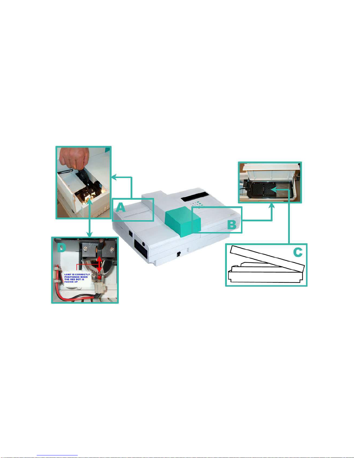
2.2 Bioscreen C Reader
The reader includes three interrelated systems: mechanical transport, incubator and optical system (for the
elements, see Figure 1). These three systems work in a coordinated way to provide automated
heating/cooling, sample indexing and OD readings.
2.2.1 Mechanical transport
The incubator tray assembly holds the Honeycomb microplates. The assembly shuttles from the microplate
loading section into the measurement compartment, where light is passed through each well of the
microplate and the detector makes the OD readings.
2.2.2 Incubator
The incubator consists of the incubator tray (fixed, non-removable), the incubator cover (on hinges) and a
temperature control system. After filling the microplate with experimental materials, the incubator cover is
placed manually on top of the incubator tray and properly closed. During the incubation and measuring, the
incubator cover remains in place.
The temperature control system maintains the incubation temperature set by the program. Ethylene glycol
and water mixture (1:1) is used as a heat transfer liquid. The liquid circulates continuously in the incubator
tray to keep the temperature stable and at a selected value. The temperature is continuously monitored and
saved by the software.
2.2.3 Optical system
The changes in turbidity or color in the culture medium, due to the growth of microorganisms, is measured
kinetically with a vertical photometer.