NT-MDT NTEGRA Spectra Probe NanoLaboratory User manual

Read me First!
Observe safety measures for operation with devices containing sources of laser radiation.
Do not stare into the beam. A label warning about the presence of laser radiation is
attached to the measuring head (Fig. 1) as well as to the laser sources.
Fig. 1
Before you start working with the instrument, get acquainted with the basic safety
measures and the operation conditions for the instrument!
If you are a beginner in scanning probe microscopy, we recommend you to familiarize with
basic SPM techniques. “Fundamentals of Scann ing Probe Microscopy” by V.L. Mironov
gives a good introduction to the subject. T his book is available on the Internet,
http://www.ntmdt.com/manuals.
Feedback
Should you have any questions, which are not explained in the manuals, please contact
give you comprehensive answers. Alternatively, you can contact our staff on-line using
the ask_on-line service.

User’s documentation set
The following manuals are included into the user’s documentation set:
-Instruction Manual – is the guidance on preparation of the instrument and other
equipment for operation on various techniques of Scanning Probe Microscopy. The
contents of the user’s documentation set may differ depending on the delivery set of the
instrument.
-SPM Software Reference Manual – is the description of the control program
interface functions, all commands and functions of the menu and, also a description of
the Image Analysis module and the Macro Language “Nova PowerScript”.
-Control Electronics. Reference Manual – is the guide to SPM controller,
Thermocontroller and Signal Access module.
Some equipment, which is described in the manuals, may not be included into your
delivery set. Read the specification of your contract for more information.
The manuals are updated regularly. Their latest versions can be found in the site of the
company, in the section “Customer support” (http://www.ntmdt.com/support).

NTEGRA Spectra Probe NanoLaboratory. (Inverted Configuration with Solar TII spectrometer)
NTEGRA Spectra Probe NanoLaboratory. Inverted Configuration
with Solar TII spectrometer
Table of Contents
1. OVERVIEW .............................................................................................................................................5
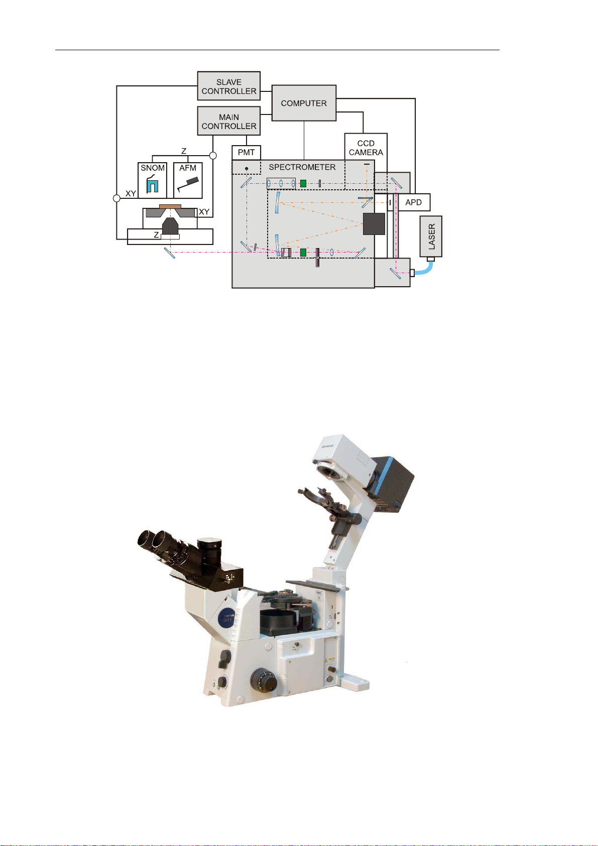
2. DESIGN.....................................................................................................................................................7
2.1. INVERTED OPTICAL MICROSCOPE .................................................................................................... 8
2.2. NTEGRA BASE UNIT....................................................................................................................... 9
2.3. XY SCANNING OPTICAL EXCHANGEABLE MOUNT......................................................................... 10
2.4. MEASURING HEADS........................................................................................................................ 12
2.5. SPECTROMETER .............................................................................................................................. 16
2.6. DETECTORS .................................................................................................................................... 16
2.7. LASER............................................................................................................................................. 20
2.8. OPTICAL FIBER TRANSPORT SYSTEM ............................................................................................. 21
2.9. ADDITIONAL CABLES ..................................................................................................................... 22
2.10. CONTROLLERS................................................................................................................................23
2.11. COMPUTER ..................................................................................................................................... 24
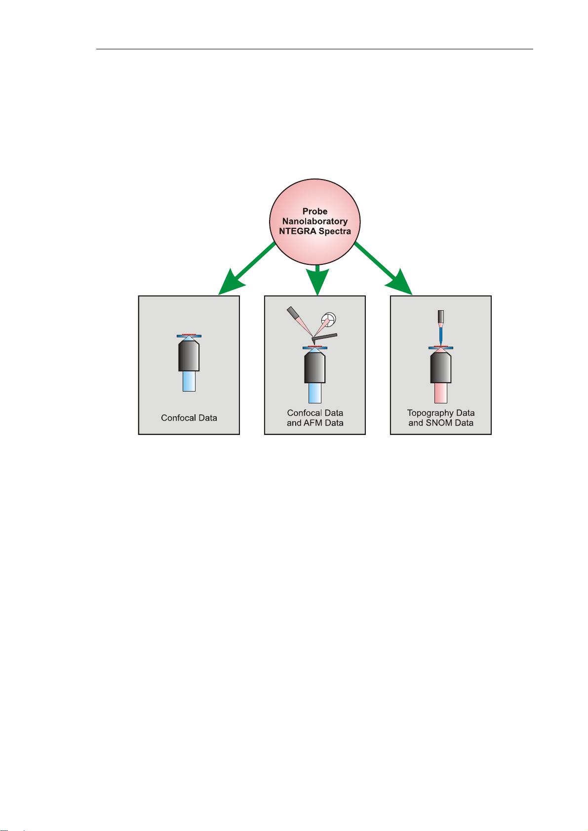
3. PRINCIPLE OF OPERATION OF THE NTEGRA SPECTRA PNL..............................................25
4. BASIC SAFETY MEASURES..............................................................................................................28
5. OPERATING CONDITIONS...............................................................................................................31
6. STORAGE AND TRANSPORT REGULATION ...............................................................................33
7. GENERAL REQUIREMENTS ON INSTALLATION......................................................................34
8. SETUP AND INSTALLATION............................................................................................................35
8.1. PREPARING THE SPECTROMETER .................................................................................................... 35
8.1.1. Installing and Aligning the Optical Fiber Transport System........................................... 35
8.1.2. Installing the Spectrometer and the Optical Microscope ................................................ 38
8.2. CONNECTING THE ELECTROMECHANICAL UNITS............................................................................ 39
8.3. POWERING SEQUENCE .................................................................................................................... 41
9. PREPARING FOR OPERATION........................................................................................................44
9.1. LAUNCHING THE CONTROL PROGRAM............................................................................................ 44
9.2. VERIFYING ADJUSTMENT OF THE DISPLACEMENT SENSORS........................................................... 45
9.3. ADJUSTING THE SPECTRAL UNIT .................................................................................................... 46
9.4. MOUNTING THE SAMPLE ................................................................................................................ 50
10. MEASURING WITH THE CONFOCAL MICROSCOPY MODE..................................................51
10.1. FOCUSING THE LASER BEAM .......................................................................................................... 51
10.2. ADJUSTING CHANNELS OF DETECTION........................................................................................... 52
10.2.1. Adjusting Detection Parameters of the CCD-camera ..................................................... 52
10.2.2. Adjusting Detection Parameters of the PMT Module...................................................... 57
10.2.3. Adjusting Detection Parameters of the APD Module...................................................... 59
10.3. ADJUSTING SCAN PARAMETERS ..................................................................................................... 61
10.4. ADDITIONAL ADJUSTING FOR SCANNING WITH AFM HEAD ........................................................... 63
10.5. SCANNING ...................................................................................................................................... 68
10.5.1. Scanning with Recording by the CCD-Camera............................................................... 68
10.5.2. Scanning with Recording by the PMT Module ................................................................ 71
10.5.3. Scanning with Recording by the APD Module ................................................................ 72
10.6. SAVING DATA................................................................................................................................. 73
10.7. FINISHING THE WORK..................................................................................................................... 73
11. AFM AND SNOM MEASUREMENTS ...............................................................................................75

Chapter 1. Overview
1. Overview
NTEGRA Spectra PNL combines measurement capabilities of spectrometry, SNOM and
AFM, which are enhanced by SNOM-spectrometry and AFM-spectrometry.
Theses capabilities are illustrated by the conceptual scheme of Fig. 1-1.
Fig. 1-1. Conceptual scheme of the NTEGRASpectra PNL
The spectrometer is based on the infinity-corrected confocal optical scheme that provides
submicron spatial resolution (200÷300 nm in the lateral (XY) and 500÷700 nm in the
normal (Z) directions). High spectral resolution (several tenths of angstrom) is achieved
due to the Czerny-Turner optical schematics of the spectrometer. For excitation of
secondary emission, a gas or solid-state laser is employed. The spatial (XYZ) information
is acquired with a special scanning system. A more detailed description of the instrument is
provided below.
NTEGRA Spectra PNL provides the following options of measurements:
-performing spectral measurements at a certain point and acquiring spectral
characteristics of various materials when the instrument operates as a regular
spectrometer;
-measuring secondary signal intensity in the selected wavelength range in the mode of
layer-specific volumetric scanning of the area 100x100x30 μm;
-acquiring optical images of the object when the instrument operates as a regular laser
confocal microscope.
5

NTEGRA Spectra Probe NanoLaboratory. (Inverted Configuration with Solar TII spectrometer)
6
In addition to measurements, the NTEGRA Spectra PNL facilitates to perform volumetric
lithography.
The SNOM-Spectrometer configuration allows the following:
-measuring surface topography with the Shear Force Microscopy;
-in the transmission mode, measuring optical and spectral properties of the object with
the resolution achievable by the Scanning Near-field Optical Microscopy.
The AFM-Spectrometer configuration allows the following:
-detecting the object landscape with atomic resolution as well as collecting its electrical,
magnetic and nanomechanical pro;
-perties with force microscopy techniques;
-measuring optical properties relevant to the Scanning Near-Field Optical Microscopy
in scales down to atomic sizes.
The NTEGRA Spectra PNL application area includes technology processes control in
chemical, food and medicine industries, environment monitoring, isotope composition
analysis, defects control, control of impurities in pure substances, analysis of materials of
quantum electronics and semiconductor industry, fundamental research in physics,
chemistry, medicine etc.
The instrument layout is quite flexible for the experimenter to change the configuration
with units designed especially for a given purpose. The software is advanced to facilitate:
-performing spectral measurements;
-controlling the scanning mechanism, the automated optical mechanical units, the light
detection systems (CCD camera and APD module);
-displaying 3D data, filtering, analysis and saving the collected data.

Chapter 2. Design
2. Design
Fig. 2-1 shows general view of the NTEGRA Spectra PNL instrument.
Fig. 2-1. NTEGRASpectra PNL
NTEGRA Spectra PNL consists of the following main parts:
-Inverted optical microscope Olympus IX71.
-Base Unit of NTEGRA.
-XY scanning optical exchangeable mount.
-Measuring heads:
-SNOM;
-AFM.
-Spectrometer.
-Light detection systems:
-CCD camera;
-APD module;
-PMT module.
-Lasers.
-Optical fiber transport system (OTS).
-Main and slave controllers.
-Computer.
The main units of the NTEGRA Spectra PNL are shown in the block diagram of the
Fig. 2-2.
7

NTEGRA Spectra Probe NanoLaboratory. (Inverted Configuration with Solar TII spectrometer)
Fig. 2-2. NTEGRASpectra PNL block diagram
2.1. Inverted Optical Microscope
An inverted optical microscope Olympus IX71 (Fig. 2-3) serves for taking common optical
images. The base unit of the instrument is mounted on it.
Fig. 2-3. Inverted optical microscope Olympus IX71
8

Chapter 2. Design
The microscope is equipped with an optical system that provides the following options for
NTEGRA Spectra:
-delivering laser beam to the sample;
-delivering the light reflected from the sample to the spectrometer;
-monitoring the process of approaching the lens to the sample;
-displaying the sample image taken from the video camera of the microscope.
2.2. NTEGRA Base Unit
The base unit of NTEGRA (Fig. 2-4) is the base platform for mounting the exchangeable
mount and the protective hood.
Fig. 2-4. Main components of the base unit
1 – approach lever; 2 – manual approach knob;
3 – temperature and humidity sensor; 4 – LC-display
The base unit includes the approach system that is used to approach the lens to the sample.
For manual operation, the manual approach knob 2 is used.
Data on ambient temperature and humidity are measured with the sensor 3 and then
displayed by the LC-display 4.
Base unit electrical slots
Slots for connecting the devices installed on the base unit:
HEAD – two identical connectors for connecting the measuring head;
SCANNER – scanner connector, used for connecting either the exchangeable
scanner or the measuring head scanner;
SCAN+SENSOR – connector for the scanner or for the scanner with built-in sensors,
used for connecting either the exchangeable scanner or the measuring
head scanner;
9

NTEGRA Spectra Probe NanoLaboratory. (Inverted Configuration with Solar TII spectrometer)
Т–connector of a heating element, used for connecting a heating stage, heating
liquid cells etc.;
SM – connector of the stepper motor;
AFAM – connector of the ultrasonic piezoelectric transducer;
BV – bias voltage jack, used for applying bias voltage to the sample.
Slots for connecting the bias unit to the control system:
CONTROLLER 1 – connector for connecting to the HEAD connector of the SPM
controller;
CONTROLLER 2 – connector for connecting to the CONTROLLER 2 connector of the
SPM controller;
CONTROLLER T– connector for connecting to the thermocontroller.
2.3. XY Scanning Optical Exchangeable Mount
XY Scanning Optical Exchangeable Mount (Fig. 2-5) allows:
-manual positioning of the measuring head in the XY plane;
-manual positioning of the sample by means of micrometer screws;
-precise positioning of the sample by means of the built-in XY scanner;
-manual approaching the lens to the sample by means of a stepper motor;
-fine focusing by means of the Z piezo drive of the lens.
The XY Scanning Optical Exchangeable Mount holds the investigated sample, the
measuring head, and the lens of the inverted optical microscope.
A substrate with a mounted sample is fastened to the sample stage 4 with the spring clips 5.
The seats 1 of the exchangeable mount hold the measuring head. Positioning of the
measuring head with respect to the lens is performed by means of screws 2. To select the
scan area, the sample is moved using the micrometer screws 3 of the XY positioning
device and inspected with the optical viewing system.
10

Chapter 2. Design
Fig. 2-5 XY Scanning Optical Exchangeable Mount
1 – measuring head seats; 2 – measuring head positioning screws;
3 – XY positioning device micrometer screws; 4 – sample stage;
5 – spring clips; 6 – scanning platform
The scanning platform 6 serves to move the investigated sample in the process of XY
scanning. It provides scanning in the wide range, high positioning precision and high
linearity of the sample displacement. Linearity of scanning with this platform is better than
that of scanning with the measuring head. Furthermore, during SNOM measurements, it
allows to keep the area under investigation within the lens focus.
The lens is mounted into the “cup” (Fig. 2-6) inside the exchangeable mount. The “cup” is
designed to approach the lens to the sample with the manual approach knob (see 2 on
Fig. 2-4). As well, it is equipped with a piezoelectric element for fine focusing the lens on
the sample and for Z-scanning.
Fig. 2-6. Inside “cup”
11

NTEGRA Spectra Probe NanoLaboratory. (Inverted Configuration with Solar TII spectrometer)
Exchangeable mount technical specifications:
XY measuring head travel 55 mm
XY positioning device travel 55 mm
XY positioning device translation resolution 5 µm
XY scanning range 100100 µm
Lens focusing range with Z piezo drive 50 µm
NOTE. In some delivery sets, XY scanning range of the scanning optical mount is
50
50
m.
2.4. Measuring Heads
Scanning probe measuring heads available in NTEGRA Spectra PNL extend performance
of the device. They facilitate investigations with techniques quite distinct from the
confocal measurements. For example, topography of the sample surface with atomic
resolution can be acquired. For details on measurements with SNOM and AFM measuring
heads, refer to PNL NTEGRA Solaris and PNL NTEGRA. Performing Measurements.
SNOM Measuring Head
The SNOM measuring head (Fig. 2-7) is used both for measurements of surface
topography of the sample and for measurements of its near-surface optical properties.
Detection of probe oscillation amplitude and phase is also available for those modes.
Fig. 2-7. SNOM measuring head
1 – output orifice for the optical fiber; 2 – leveling posts;
3 – probe holder; 4 – housing; 5 – mounting plate; 6 – motorized leveling post
12

Chapter 2. Design
All elements of the SNOM measurement head are assembled on the mounting plate 5 and
contained within the housing 4. The capacitance sensors are fixed to the bottom part of the
scanner. The end of the scanner has a special holder for the optical fiber probe 3. The top
part of the housing 4 has an output orifice 1 for the free end of the optical fiber.
There are three leveling posts to secure installation, horizontal leveling and approaching of
the probe to the sample. Two of them (pos. 2) are ordinary screws with fastening nuts. The
third post is a micrometer screw driven by a stepper motor 6 (motorized leveling post) that
provides the motorized translation of the probe towards the sample.
The probe is fixed in the holder 1 (Fig. 2-8) with spring clips 2, which also serve as
electrical contacts to acquire signal from the sensor. During installation of the sensor, the
optical fiber is pulled through the orifice 5. The scanner 3 provides scanning of the selected
XY area of the sample by the probe. It tracks the surface landscape. Observation of the
probe tip during the approach procedure or scan area selection is available through a
special groove in the protective case 4.
Fig. 2-8. Probe holder assembly
1 – probe holder; 2 – spring clips; 3 – bottom of the scanner;
4 – protective case; 5 – optical fiber input orifice
The measuring head also provides approaching the probe to the sample surface to the
operating distance and maintaining that distance during probe scanning of the sample.
Position of the probe in the XY plane during scanning is controlled with capacitance
sensors.
Technical specifications of the SNOM measuring head:
Scan range:
-in XY plane 100×100 m
-in Z direction 7 m
13

NTEGRA Spectra Probe NanoLaboratory. (Inverted Configuration with Solar TII spectrometer)
Resolution:
-shear Force method:
in XY plane < 100 nm
in Z direction < 1 nm
-optical method:
in XY plane ~ 100 nm
in Z direction –
Number of pixels up to 1024×1024
Probe-to-sample approach mode automated (motorized)
AFM measuring head
The AFM measuring head (Fig. 2-9) is used for qualitative and quantitative measurements
of near-surface characteristics of various objects and properties of physical fields
associated with these objects.
Fig. 2-9. AFM measuring head
1 – laser adjusting screws; 2 – photodiode adjusting screws;
3 – probe holder; 4 – housing; 5 – mounting plate; 6 – leveling posts
The measuring head consists of the mounting plate 5 with other components assembled on
it. Capacitance sensors, which determine the position of the scanner, are fixed to the
bottom of the scanner. The end of the scanner has a special holder for the probe 3.
14

Chapter 2. Design
There are three leveling posts to secure installation, horizontal leveling and approaching of
the probe to the sample. Two of them (pos. 6) are ordinary screws with fastening nuts. The
third post is a micrometer screw driven by a stepper motor 6 (motorized leveling post) that
provides the motorized translation of the probe towards the sample.
The laser adjusting screws 1 are used to aim the laser beam at the probe. The beam
reflected from the probe is acquired by the photodiode. The adjusting screws 2 provide
aligning the photodiode against the beam.
Fig. 2-10. Probe holder assembly
1 – probe; 2 – sapphire pedestal; 3 – spring clip; 4 – trapezium lever
Design of the probe holder is shown in Fig. 2-10. The probe 1 is set on the sapphire
pedestal 2 and is fixed by the spring clip 3. The clip is loosened and tightened by the
trapezium lever 4. A piezodriver is located under the sapphire pedestal. Its function is to
excite oscillations of the cantilever at a given frequency during measurements on semi-
contact techniques.
Technical specifications of the AFM measuring head:
Scan range:
-in XY plane 100×100 m
-in Z direction 10 m
15

NTEGRA Spectra Probe NanoLaboratory. (Inverted Configuration with Solar TII spectrometer)
2.5. Spectrometer
Raman spectrometer (Fig. 2-11) is used to carry out spectroscopy and to form the image. A
detailed description is given in the manual Raman Spectrometer. User’s Manual.
Fig. 2-11. Raman spectrometer
Modularity of the spectrometer structure, a wide variety of lasers and microscopes,
high-precision elements for operation with three laser, automatic adjustment of optical
components after switching between the lasers – all this factors make the system flexible
thus enabling a wide range of applications to perform.
Spectrometer technical specifications:
Wavelength of working range 244÷1050 nm
Diffraction gratings vary with the delivery set
Spectral resolution 0.1 Å
Focal length 520 mm
2.6. Detectors
CCD-camera
CCD-camera (Fig. 2-12) provides a wide measurement range and has brilliant spectral and
time characteristics. It contains a built-in thermoelectrical cooling system (Peltier element),
which allows to cool the CCD-matrices down to –90 °С.
16

Chapter 2. Design
Fig. 2-12. CCD camera
CCD-camera technical characteristics
Parameter Value
Quantity of sensors (pixels) 1024×255
Sensing element size 26 m2
Active area size 26.6×6.7 mm2
Vertical scanning rate 16 ms
NOTE. Model of the CCD-camera can change without prior notice.
APD module
Avalanche photodiode (APD module) (Fig. 2-13) serves for counting photons during a
predefined time intervals. It contains a built-in cooling system which provides cooling the
device thus lowering the thermal noise.
Fig. 2-13. APD module
17

NTEGRA Spectra Probe NanoLaboratory. (Inverted Configuration with Solar TII spectrometer)
Fig. 2-14. Spectral range
APD module technical characteristics
Parameter Value
Ambient temperature +5 ÷ 40 ºC
Working range at temperature 22ºC 400 ÷ 1060 nm
Active area diameter 175 m
Maximum light intensity 10 000 photons/sec
NOTE. In some configurations of NT EGRA Spectra PNL, the ADP module is
missed or replaced by a cooled PMT.
PMT module
Photomultiplier module (PMT module) (Fig. 2-15) serves for converting optical radiation
acquired from the sample into electrical signals.
18

Chapter 2. Design
Fig. 2-15. PMT module
Fig. 2-16. Photomultiplier sensitivity Fig. 2-17. Effective spectral range
PMT module technical characteristics 25 °C
Parameter Value
Sensitivity (at 420 nm) 3.0×10¹⁰ V/W
Operating spectral range 185÷850 m
Output voltage shift ±3 mV
Current-to-voltage conversion gain 1×10⁶V/A
Frequency range from 0 to 20 kHz
19

NTEGRA Spectra Probe NanoLaboratory. (Inverted Configuration with Solar TII spectrometer)
2.7. Laser
ATTENTION! Direct or scattered laser radiation is hazardous and may
cause eye injuries.Avoid direct eye exposure to beam.
The delivery set of the NTEGRA Spectra PNL contains the LM473 solid-state laser with
diode pumping. General view of the laser is shown in Fig. 2-18. The lasers of this series
are compact, with high degree of beam polarization and good output power stability. The
laser comprises two units, the power supply unit and the laser head. Detailed information
on the laser set-up, powering sequence, alignment procedure, and precaution measures is
given in a corresponding manual supplied with the PNL.
Besides, equipping the PNL with additional lasers of wide wavelength range (from 350 to
850 nm) is available.
Fig. 2-18. General view of the laser
Specifications of the solid-state laser
Parameter Value
Transverse mode TEM00
Wavelength 473 nm
Polarization Linear
Degree of polarization > 100:1
Output power max 50 mW
Power Stability ±0.5 % (2 hr)
Beam Pointing Stability < 30 umrad/°C
Beam divergence (1/e2) < 1.2 mrad
Long-Term Drift < 3 %
Warm-up Period < 15 minutes
Operating temperature 10 ÷ 40 ºС
20
Table of contents
Other NT-MDT Laboratory Equipment manuals
Popular Laboratory Equipment manuals by other brands

BioChain
BioChain AnaPrep 12 Dx instruction manual

Armfield
Armfield CEM-MKII instruction manual

Dürr Technik
Dürr Technik SICOLAB mini ENDO Installation and operating instructions

Agilent Technologies
Agilent Technologies 1260 Infinity user manual

Phcbi
Phcbi PR-L5181W-PA operating instructions

Koehler
Koehler K430 5 Series Operation and instruction manual