Grozone Control LS8 User manual

USER GUIDE
LS8/sLS8
Light Switcher/Smart Light Switcher
www.grozonecontrol.com

TABLE OF CONTENTS
WARNINGS & CAUTION.............................................................1
LS8/SLS8 GENERAL DESCRIPTION...............................................2
SPECIFICATIONS ........................................................................3
INSTALLATION GUIDE..............................................................4-5
TROUBLESHOOTING…………………………….………………...……..……..6-
WARRANTY & CUSTOMER SERVICE ……………………….……..……...8-9

•
This product must be installed by a Licensed electrician only
•
Read all instructions before operating the LS8/sLS8
•
This light switcher is designed to work with electronic and
magnetic ballasts
•
Protect your LS8/sLS8 against water or any sprayed products
•
Mount your LS8/sLS8 securely to the wall using included hardware
•
Do not attempt to repair the LS8/sLS8 yourself call Grozone
Control technical support 855-262-1800
•
Make sure to verify your electrical panel components and capacity
prior to wiring your LS8/sLS8 into the power source
•
Plug in 240 V loads only
FOR SUPPLY CONNECTIONS, USE 8 AWG OR LARGE WIRES SUITABLE
FOR AT LEAST 75°C (167°F). USE COPPER WIRE ONLY.
1
WARNING & CAUTIONS

The LS8 Light Switcher is specifically designed to operate a high intensity
discharge (HID) lighting systems. The system can handle up to a maximum of
eight (8) 1000 watt HID metal halide (MH) or high pressure sodium (HPS) grow
lights. The activation of the internal power switches (relays) is performed
through 120V trigger inputs. The LS8 can activate 8 lights with one single trigger
input or two 4-light zones using two trigger inputs with LS8 Dual Zone. This
light switcher provides up to 40 amps of capacity on a standard 240 volts
circuit. There is a 120V service outlet (max 10A); this is intended to use with a
ventilation fan light movers timers or any other accessory. The LS8 is built with
only the highest quality components and will provide you with years of trouble
free performance.
The sLS8 integrates a high temperature shut-off function that turns off 1 2
or 3 of the 4 zones if room temperature goes above the preset temperature
limit. sLS8 provides a remote temperature sensor and a PCB-mount slide
switch to set temperature limits. Refer to page 5 for more information.
2
LS8 / sLS8 GENERAL DESCRIPTION

LS8
•
Number of lights : 8 lights single zone or dual zone model.
•
Number of 120V trigger inputs: 1 for single 8-light zone. Second trigger input
to control two 4-light zones separately with dual zone model.
sLS8:
•
Number of lights : total of 8 lights 4 zones of 2 lights.
•
Number of 120V trigger input: 1
COMMON SPECIFICATIONS
•
Light receptacles: NEMA 6-
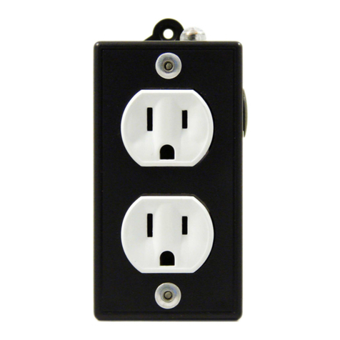
15 (240V 15A) 4 duplex receptacles for 8 lights
4 lights on each side.
•
Service receptacle: NEMA 5-15 (120V 10A).
•
Metal enclosure dimensions: 14 in. X 10.5 in. X 2.5 in. (H x W x D)
•
Circuit breakers: total of 4 double breakers (240V 15A) 1 double breaker
for two lights. Breakers meet UL 489.
•
Input power requirement: 240V 40A 60Hz.
SPECIFICATIONS
3

IMPORTANT: THIS PRODUCT MUST BE INSTALLED BY A
LICENSED ELECTRICIAN ONLY
1. Unscrew the 4 cover screws.
2. Secure the LS8/sLS8 to the wall using the included hardware (#8 wood screws
in keyhole shaped mounting holes).
3. Use the correct size wire for your application. Please check local electrical
codes for wire size requirements. Carefully strip the 2 power wires
approximately 1’’. Pass the stripped and copper wires through the largest
strain relief located on bottom wall of enclosure.
Hook up 240V wires as follows:
•
Black wire to JP5 connector L1
•
Red or White wire to the
JP5 connector L2
•
Copper wire to GROUND LOG located
on bottom wall of enclosure next to
metallic wire connectors.
IMPORTANT NOTICE:
2 POWER CONNECTOR models are available - follow instructions accordingly.
Gray Spring Terminal (shown below): insert small flat screwdriver at 45°
into
square hole pry tool downward to open contact insert appropriate wire then
release tool. Tighten up wire connectors (strain relief).
Black Screw Terminal (not shown): loosen terminal screws insert appropriate
wire under screw plate then tighten up screws and wire connectors
(strain relief).
INSTALLATION GUIDE
4

4. sLS8 ONLY:
Set high temperature limits by sliding the switch to preferred preset values.
sLS8 provides 3 different settings:
•
Setting 1: high temperature function is disabled
then sLS8 works as a LS8.
•
Setting 2:
- Limit to turn 1st zone OFF: 27°C / 80°F
- Limit to turn 2nd zone OFF: 28.5°C / 83°F
- Limit to turn 3rd zone OFF: 30°C / 86°F
•
Setting 3:
- Limit to turn 1st zone OFF: 30°C / 86°F
- Limit to turn 2nd zone OFF: 31.5°C / 89°F
- Limit to turn 3rd zone OFF: 33°C / 92°F
sLS8 High Temperature Shut-Off Operation :
In order to maintain the room temperature below the preset temperature limits the
sLS8 may need to turn off 1 2 or 3 zones each zone comprising 2 lights. To ensure an
even distribution of the light in your grow room the sLS8 features smart zone rotation
that changes the OFF zone(s) from zone 1 to zone 4 alternately.
Preset high temperature limits are made up of 3 values:
•
When room temperature reaches the 1st value only 1 zone will turn off.
•
If room temperature reaches the 2nd value a second zone will turn off.
•
Finally if room temperature reaches the 3rd value a third zone will turn off.
NOTE : when a high temp condition is met turning 1 zone OFF should enable room
temperature to return to normal condition. Turning 2 or 3 zones OFF may occur when
cooling equipment or outdoor temperature reach extreme conditions. In the worst
case (3 zones OFF) there will always be a minimum of 1 zone with its lights ON to
maintain the photoperiod in your grow room.
Replace cover and tighten up screws.
Do not over tighten to prevent stripping screw threads.
5
.
INSTALLATION GUIDE
5
Maximum OFF period: the zone rotation function ensures that OFF periods never
exceed 1 hour per zone.
Minimum OFF period: to prevent hot start OFF periods last a minimum of 20
minutes even though room temperature has cooled down below limits in less than
20 minutes.

Problems Actions
The lights will not turn on
Verify that there is power to the 120V
trigger input. You will hear a loud
“click” caused by relay switching when
power is applied to the trigger input.
Check if the main circuit breaker and
the LS8/sLS8 breakers are in the ON
position and reset them if necessary.
Verify that the unit is wired properly.
Check with a licensed electrician if
there are any concerns regarding
proper installation of your LS8/sLS8
put the switch in position #1.
There is no power on one side of your
LS8/sLS8
(A and B zones on the left side
C and D zones on the right side)
Check if the corresponding LS8/sLS8
breakers have tripped. The breaker
actuator must be firmly engaged in the
ON position (UP).
sLS8 put the switch in position #1.
LS8 Dual Zone check if both of your
trigger cord are properly plug in the
wall.
TROUBLESHOOTING
6

Problems Actions
The main circuit breaker keeps
tripping.
Check the main circuit breaker in the
electrical panel the breaker value must
be at least 50A to meet most of
North-American electrical codes.
Please consult with a licensed
electrician.
Still having problem with your LS8/sLS8?
Please contact Grozone Control Technical Support at
855-262-1800 or by email service@grozonecontrol.com
TROUBLESHOOTING

DO YOU HAVE A PROBLEM WITH YOUR LS8/sLS8 ?
PLEASE READ THESE
INSTRUCTIONS CAREFULLYAND SAVE THEM FOR FUTURE REFERENCE
1. I think my LS8/sLS8 is damaged, or it simply does not work as indicated
in the user guide, what should I do?
•
Please refer to the troubleshooting steps. Follow these instructions carefully
step by step. The LS8/sLS8 should work as described in the “Actions” column
of the Complete Troubleshooting Guide.
Do you need assistance on executing the Troubleshooting steps?
1. Contact us at 1-855-262-1800
2. Send us an EMAIL at service@grozonecontrol.com or
3. VISIT our Technical Support Center at www.grozonecontrol.com/
techsupport.html
Technical Support is available Monday through Friday, from 8:00 AM to 8:00 PM,
Eastern Time.
WARRANTY & CUSTOMER SERVICE
8

2. I’ve been through the troubleshooting steps, what do I do if I meet a
problem at any of these steps? Is my product covered by the WARRANTY?
•
The LS8/sLS8 is covered by a 1-year warranty (*). We will replace any
DAMAGED PRODUCT WITH A BRAND NEW PRODUCT.
•
Covered or not covered? We do not authorize the replacement of fully
working products nor altered (tampered) products. The Troubleshooting
steps will help you identify a damaged product. Do not hesitate to contact
us or contact your retailer to make sure the controller is not fully working or
damaged before returning it to the store.
•
My product is not fully working or damaged I want a replacement unit:
in order to get a replacement product you MUST return all modules and
applicable accessories to the retailer. To avoid being charged for the
accessories be sure to include all pieces. Thanks for your cooperation.
•
Any Grozone Control product that is returned with obvious signs of user
neglect will not be covered by warranty. Grozone Control exercises the right
to make final decisions in these matters.
IMPORTANT MESSAGE TO RETAILER
The retailer must call Grozone Control to get authorisation to replace
the defective product and a RMA number.
1-855-262-1800
(*)The warranty period begins from the date of purchase at the retail level. The
retailer/consumer must keep their proof of sale/purchase. Otherwise Grozone
Control will consider the manufacturing date to apply the warranty coverage.
9
WARRANTY & CUSTOMER SERVICE

NOTE
__________________________________________________________________
__________________________________________________________________
__________________________________________________________________
__________________________________________________________________
__________________________________________________________________
__________________________________________________________________
__________________________________________________________________
__________________________________________________________________
__________________________________________________________________
__________________________________________________________________
__________________________________________________________________
__________________________________________________________________
__________________________________________________________________
__________________________________________________________________
__________________________________________________________________
__________________________________________________________________

www.grozonecontrol.com
Guide de l’usager
LS8/sLS8
Commutateur de lampes intelligent

MISE EN GARDE ET PRÉCAUTIONS………………...….…1
DESCRIPTION GÉNÉRALE DU LS8/SLS8……..……..…….2
CARACTÉRISTIQUES…………………………………….…..3
INSTALLATION ET OPÉRATION…………………….…...4-5
GUIDE DE DÉPANNAGE……………………………..……..6-7
SERVICE À LA CLIENTÈLE ET GARANTIE……….…...8-9
TABLE DES MATIÈRES

•
Ce produit doit être installé par un électricien certifié.
•
Avant d’utiliser le LS8/sLS8 assurez-vous d’avoir lu les instructions.
•
Ce commutateur de lumière est conçu pour fonctionner avec des ballasts
électroniques et magnétiques.
•
Assurez-vous d’installer votre LS8/sLS8 au mur de façon sécuritaire avec les
vis et rondelles incluses.
•
Ne tentez pas de réparer le LS8/sLS8 vous-même appelez le support
technique de Grozone Control au 855-262-1800.
•
Assurez-vous de vérifier la capacité ainsi que les composants de votre
panneau électrique avant de câbler le LS8/sLS8 à la source d’alimentation.
•
Branchez des charges de 240V seulement.
POUR LES CONNEXIONS D'ALIMENTATION, UTILISEZ DU
FIL 8 AWG OU PLUS GROS CONVENANT POUR AU MOINS
75°C (167°F). UTILISEZ DU FIL DE CUIVRE UNIQUEMENT.
MISE EN GARDE ET PRÉCAUTIONS
1

Le commutateur de lumière LS8 est spécifiquement conçu pour opérer des
systèmes d’éclairage HID (décharge à haute intensité). Le LS8 peut gérer jusqu’à
un maximum de 8 lampes MH ou HPS de 1000 watts. L’activation des relais
internes est effectuée par le biais d’entrées d’activation 120V. Le LS8 peut activer
8 lumières par une seule entrée d’activation ou encore peut activer 2 zones de 4
lumières par 2 entrées d’activation distinctes. Ce commutateur de lampes peut
fournir jusqu’à 40 ampères sur un circuit standard de 240 volts. Le LS8 comprend
une prise de service 120V (10A max) pour l’utilisation d’accessoires comme des
ventilateurs minuteries rails pour lampes ou autres. Le LS8 est construit
uniquement avec des composantes de haute qualité vous donnant ainsi des
années de fonctionnement sans tracas.
Le sLS8 intègre un coupe-circuit en haute température qui éteint 1 2 ou 3 des 4
zones si la température de la pièce dépasse les limites prédéfinies. Le sLS8
possède un capteur de température externe et un sélecteur des limites de
température monté sur le circuit imprimé. Pour plus d’information voir page 5.
DESCRIPTION GÉNÉRALE DU LS8 / sLS8
2

•
Nombre de lumières: 8 lumières (4 zones de 2 lumières).
•
Nombre d’entrées d’activation 120V: 1 entrée pour 1 zone de 8 lumières
pour le LS8 ou sLS8. Deux entrées pour contrôler 2 zones de 4 lumières pour
le LS8 Dual Zone.
•
Type de prise de courant: NEMA 6-15 (240V 15A) 4 sorties doubles pour un
total de 8 lumières 4 prises de chaque côté.
•
Prise de service: NEMA 5-15 (120V 10A).
•
Dimension du boîtier: 14 in. X 10.5 in. X 2.5 in.
•
Disjoncteurs: 4 disjoncteurs doubles (240V 15A) 1 disjoncteur pour 2
lumières rencontrent UL 489.
•
Circuit d’alimentation: 240V 40A 60Hz.
•
Certifié ETL.
CARACTÉRISTIQUES
3

IMPORTANT: CE PRODUIT DOIT ÊTRE INSTALLÉ PAR UN
ÉLECTRICIEN CERTIFIÉ SEULEMENT
1. Dévissez les 4 vis du couvercle.
2.
De façon sécuritaire installez le LS8/sLS8 au mur avec la quincaillerie incluse
(vis à bois #8) dans les trous en forme de goutte.
3. Il est important d’utiliser un câble de calibre approprié à votre application,
référez-vous au code d’électricité local. Dégainez les 2 fils ‘’vivants’’ d’environ
1”. Passez les fils dégainés et le cuivre dans le grand serre-câble situé sur la
paroi inférieure du LS8/sLS8.
IMPORTANT :
Deux types de connecteurs d’alimentation sont disponibles; veuillez utiliser
les instructions appropriées.
Connecteur gris à ressort (illustré): insérer un petit tournevis à 45° dans le
trou carré ouvrir le contact en poussant l’outil vers le bas insérer le fil et
relâcher l’outil. Assurez-vous de bien serrer les vis du serre-câbles.
Connecteur à vis noir (non illustré): dévisser les vis insérer le fil sous la
plaque retenue par la vis serrez les vis du connecteur et du serre-câbles.
INSTALLATION ET OPÉRATION
4
Branchez les fils du 240V tel qu’illustré :
•
Noir : connecteur JP5 borne L1
•
Rouge ou blanc : connecteur JP5
borne L2
•
Fil de cuivre au connecteur de mise à
la terre situé sur la partie inférieure
du boîtier près des serre-câbles
métalliques.

4. sLS8 seulement:
Ajustez les limites de température en glissant le sélecteur sur la valeur desirée.
Opération du coupe-circuit en température du sLS8 :
Afin de maintenir la température de la pièce sous les limites prédéfinies le sLS8
pourrait éteindre 1 2 ou 3 zones chaque zone comprenant 2 lampes. Pour assurer
une distribution d’éclairage égale dans votre pièce le sLS8 assurera une rotation des
zones éteintes de la zone 1 à la zone 4 en alternance.
Les limites prédéfinies en haute température contiennent trois seuils :
•
Quand la température de la pièce atteint le 1er seuil une seule zone est éteinte.
•
Quand la température de la pièce atteint le 2e seuil une 2e zone est éteinte.
•
Enfin quand la température de la pièce atteint le 3e seuil une 3e zone est éteinte.
NOTE : quand une condition de haute température est rencontrée le fait d’éteindre une pre-
mière zone devrait suffire à ramener la température à un niveau normal. Le besoin d’éteindre
une 2e ou 3e zone pourrait survenir si les équipements de refroidissement ou la température
extérieure atteignent des conditions extrêmes. Dans le pire scénario le sLS8 conserve toujours
un minimum d’une zone allumée afin de maintenir la photopériode dans votre pièce.
Durée maximale d’une zone éteinte
: la fonction de rotation des zones éteintes assure
que chaque zone sera éteinte au maximum une heure.
Durée minimale d’une zone éteinte: afin d’éviter une condition de “hot start” une
zone est toujours éteinte pour un minimum de 20 minutes même si la température
de la pièce a refroidi sous le seuil prédéfini en moins de 20 minutes.
INSTALLATION ET OPÉRATION
5
Le sLS8 offre trois configurations prédéfinies :
•
Config. 1: le coupe-circuit haute température
est DÉSACTIVÉ; le sLS8 devient un LS8.
•
Config. 2:
- Seuil pour éteindre 1ière zone : 27°C / 80°F
- Seuil pour éteindre 2e zone : 28.5°C / 83°F
- Seuil pour éteindre 3e zone : 30°C / 86°F
•
Config. 3:
- Seuil pour éteindre 1ière zone: 30°C / 86°F
- Seuil pour éteindre 2e zone : 31.5°C / 89°F
- Seuil pour éteindre 3e zone : 33°C / 92°F
Visser le couvercle du LS8/sLS8 avec le matériel inclus. Ne pas trop serrer
pour éviter d’endommager les filets des vis dans la tôle mince du boîtier.
5
.

Problèmes Actions
Les lumières n’allument pas.
Vérifiez la connexion du câble
d’activation 120V et assurez-vous qu’il
y ait du courant sur celui-ci. Vous
entendrez un ‘’clic’’ venant du relais
quand on applique du courant sur
l’entrée d’activation.
Vérifiez que le disjoncteur du
panneau électrique et ceux du
LS8/sLS8 soient en position ON
sinon les mettre à ON.
Assurez-vous que le LS8/sLS8 soit
branché correctement.
Pour sLS8 mettre l’interrupteur à la
position #1.
Consultez un électricien certifié pour
l’installation de votre LS8/sLS8.
Il n’y a pas de courant sur un côté
du LS8/sLS8.
(Zones A et B sur le côté gauche
zones C et D sur le côté droit)
Vérifiez que les disjoncteurs de la zone
en question soient en position ON.
Pour sLS8 mettre l’interrupteur à la
position #1.
Pour Le LS8 Dual Zone vérifier si les 2
cordons sont branchée dans la prise
électrique ou dans le minuteur.
GUIDE DE DÉPANNAGE
6
This manual suits for next models
1
Table of contents
Languages:
Other Grozone Control Switch manuals
Popular Switch manuals by other brands

Alaxala
Alaxala AX1250S Series manual

ZyXEL Communications
ZyXEL Communications MSC1000G Series user guide

Well
Well WRC5000N user manual

Endress+Hauser
Endress+Hauser Liquipoint FTW 31 manual

Wave Italy
Wave Italy IMPETUS Installation, use and maintenance manual

Edge-Core
Edge-Core ECS2000-26T installation guide

Compaq
Compaq StorageWorks SAN Switch Integrated/32 Installation and hardware guide

Digital Data Communications
Digital Data Communications Level One GTL-2091 manual

Leonton
Leonton BG5-1204-SFP-24 Series user manual

Belkin
Belkin 16-Port Gigabit Switch user manual

ATEN
ATEN ATEN MasterView KVM CS-62 user manual

Hawking
Hawking UH214 Specifications