Grumman American AA-5 User manual

FAA
Aircraft Certification Service SPECIAL AIRWORTHINESS
INFORMATION BULLETIN
SAIB: CE-09-37
SUBJ: Stabilizer: True Flight (Grumman American) AA-5 Date: July 1, 2009
This is information only. Recommendations aren’t mandatory.
Introduction
This Special Airworthiness Information Bulletin (SAIB) alerts you, owners and operators of True
Flight Aerospace LLC (Grumman American) Model AA-5 airplanes, of an issue concerning the
horizontal stabilizer forward spar attachment and surrounding structure in the aft fuselage area.
At this time, this airworthiness concern is not an unsafe condition that would warrant AD action
under Title 14 of the Code of Federal Aviation Regulations (14CFR) part 39.
Background
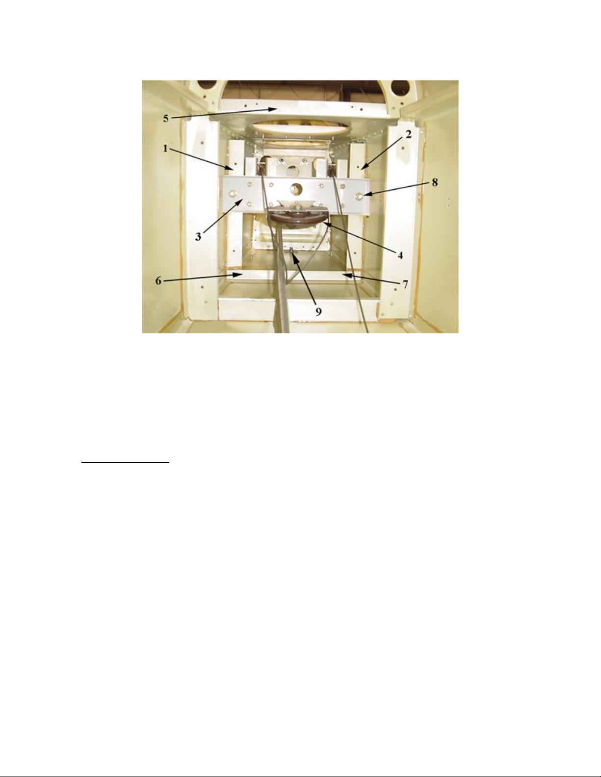
During a routine inspection, maintenance personnel found cracked and deformed structure in the aft
fuselage area including horizontal stabilizer forward spar attachment structure, spar support angles,
and stiffeners. While there are no previous reports of similar damage in the AA-5 airplanes, there
have been reports for the AA-5A and AA-5B models. In 2003, the FAA issued SAIB CE-04-34 to
inform owners of this potential issue on the AA-5A and AA-5B models and the SAIB included an
inspection of this area of the airplane. In 2003, the type certificate owner issued an update to the
maintenance manual to add instructions for this inspection for the AA-5A and AA-5B airplanes.
There are currently no clear instructions in the maintenance manual for inspecting this area of the
AA-5 model.
Recommendation
We encourage owners and maintenance personnel to perform detailed visual inspections of the
horizontal stabilizer forward spar attachment structure, and surrounding area, of the AA-5 airplanes at
the following times:
•At every annual/100 hour inspection
•After hard landings, tail strikes, or any other notable impact or force in tail area.
We’ve included a copy of the inspection instructions from the maintenance manual that were only
applicable to the AA-5A and AA-5B models for your use on the AA-5 airplane. While the structure
of the AA-5 is somewhat different in this area, True Flight Aerospace informs us that the basic
inspection points should be applicable to all of the AA-5 series models.
If you find cracks or deformation, it is always helpful to the FAA if you submit a Malfunction or
Defect Report to the FAA’s website at http://www.faa.gov/aircraft/safety/report/.
For Further Information Contact
Cindy Lorenzen, Program Manager, FAA, Central Region, Atlanta Aircraft Certification Office, One
Crown Center, 1895 Phoenix Boulevard, Suite 450, Atlanta, GA 30349; phone (770) 703-6078; fax

AA-5 Series
Maintenance Manual
HORIZONTAL STABILIZERS – MAINTENANCE PRACTICES
NOTE: It is important to inspect the horizontal stabilizer spar attach points on the fuselage after
a hard landing, wing tip strike, strike to the tail tie-down ring, or after any damage to
the empennage. The area should also be inspected prior to installation of the horizontal
stabilizer.
1. Horizontal Stabilizer Forward Spar Attach Point Inspection (AA-5A and AA-5B)
(1) Remove the aft fuselage inspection covers below the vertical fin. (Refer to Chapter 53)
(2) Remove the flashing beacon power supply. (Refer to Chapter 33)
(3) Through the large lightening hole in horizontal bulkhead (5) use a suitable light and mirror to
perform the following inspections: (Refer to Figure 3)
(a) Inspect spar support angles (1 and 2) for delamination, cracks and buckling above and
below stabilizer spar (3). Also inspect the upper flanges of the angles for cracks in or
near the bend radii.
(b) Inspect the angles for cracks or buckling around stabilizer attach bolts (8).
(c) Inspect the lower stiffener in areas (6 and 7) for cracks and/or delamination.
(d) Inspect the exterior skins on either side of angles (1 and 2) for cracks.
(4) If any damage is found, remove stabilizer spar (3) and repair or replace damaged angles (1 and
2) and stiffener (6/7) and any other damage in accordance with Chapter 20 of this manual,
Service Kit 125A and /or AC43-13.
(5) Reinstall the flashing beacon power supply. (Refer to Chapter 33)
(6) Reinstall the aft fuselage inspection covers below the vertical fin. (Refer to Chapter 53)
55-1-1
Page 201
Rev. 03/01/04

AA-5 Series
Maintenance Manual
Figure 3
Forward Horizontal Support Angles
1. RH Spar Support Angle 6. Lower Stiffener, RH side
2. LH Spar Support Angle 7. Lower Stiffener, LH side
3. Horizontal Stabilizer Forward Spar 8. Spar Attach Bolt
4. Aileron Balance Cable Pulley (reference) 9. Tail Tie-Down Attach Point
5. Horizontal Bulkhead
2. Removal/Installation (Reference Figure 4) AA-5A and AA-5B Aircraft
A. Horizontal Stabilizer Removal
NOTE: The horizontal stabilizer can be removed as an assembly, with trim tabs and elevator intact, or
by sub-assembly removal procedures, whichever is required. If the trim tabs or elevators are
being replaced, this can be accomplished without removing the stabilizer. For complete
stabilizer assembly removal, the following procedure may be used.
(1) Remove the tailcone and the aft fuselage inspection covers below the vertical fin.
(Refer to Chapter 53)
(2) Disconnect the elevator control cables and trim linkage. (Refer to Chapter 27)
(3) Remove the horizontal stabilizer fairings. (Refer to Chapter 53)
(4) Remove forward mounting bolts and washers (4) on each side of the fuselage.
NOTE: Shim stack-up, if any, between the stub spar and the stabilizer (each side) should be noted to
assist in reassembly. 55-1-1
Page 202
Rev. 03/01/04

AA-5 Series
Maintenance Manual
(5) Remove the 2 L/H center hinge mounting bolts (8) and washers (9).
(6) Remove elevator stop bolts (12) and spacers (13).
(7) Remove spar attach bolts (10) and washers (11).
(8) Pull the horizontal stabilizer aft and remove it from the aircraft.
B. Horizontal Stabilizer Installation
(1) Position the horizontal stabilizer to its installed location and check the clearance between the aft spar and the
aft fuselage bulkhead. If a gap exists, shim the forward carry through spar forward by installing 5302050-1
shims (maximum of three per side) until the aft spar is flush against the aft bulkhead. (Reference Figure 55-
03)
NOTE: The AN6 bolt length may be revised as required.
NOTE: If the forward carry through spar is shimmed, install 5302055-5 shims as necessary between
the carry through spar and the pulley bracket support assembly to align the aft attach lugs of
support assembly (7) flush with the external surface of the aft bulkhead.
(2) Install the aft spar mounting bolts (10) and washers (11). Torque to standard value. (Refer to Chapter 91)
(3) Check the clearance between the forward stabilizer spar attach points and the carry through spar. If the gap is
greater than 0.010 inch, install 5301034-3 shims (5) as required to reduce the gap to 0.010 inch or less and
install forward mounting bolts and washers (4). Torque to standard value. (Refer to Chapter 91)
NOTE: AN4 Bolt (4) length may be revised as required.
(4) Install 2 ea. AN4-13A bolts (8) through the left side of hinge (14), the rear stabilizer spar, aft bulkhead and
pulley support brace (7) and secure with washers and nuts (not numbered). Torque to standard value. (Refer
to Chapter 91)
(5) Install elevator stops (12) and spacers (13).
(6) Connect the elevator and trim linkages, and rig. (Refer to Chapter 27)
(7) Install tailcone, aft fuselage inspection covers and fairings. (Refer to Chapter 53)
55-1-1
Page 203
Rev. 03/01/04
Table of contents
Other Grumman American Aircraft manuals